Abstract
There are always clearances between the movement pairs in mechanical systems, which will deteriorate the dynamical performance of these systems when they become larger than the necessary size to allow their relative movement between the movement parts. In this paper, a special linkage mechanism for excavation with two clearances was concerned, and the effects of size of the clearance and the friction coefficient between the movement parts on the dynamical performance were investigated by modeling and numerical analysis. It shows that, with the increase of the friction coefficient and the size of clearance, the trajectory of mass center of connecting rod does not change greatly, but the dynamic response, such as the angular velocity, the impact force, and the load torque, will sharply increase, which may cause structure damage in many cases. Therefore, in the design and manufacture of this kind of mechanisms, we should find way to decrease the clearance and friction coefficient to ensure the dynamical performance.
1. Introduction
Excavating instrument with low noise is one of the important equipments in civil engineering. In the machine, clearance is inevitable, and its size will affect the dynamic response and noise. Study on clearance of machine is of essential significance. Many works on dynamic response of machine with clearance had been done by many scholars.
Different kinematic models with clearance are studied, assessing the actual configuration of a mechanism with clearance-affected pairs [1]. Imed [2] studied the dynamic behavior of a planar flexible slider-crank mechanism with clearance, using a contact model based on the impact-function. Tsai and Lai [3], using the properties of reciprocal screws to determine the instantaneous configurations, introduced a generalized method for error analysis of multi-loop mechanisms with joint clearance. Joint clearance was treated as a virtual link to simplify the study. Equivalent kinematical pair was used to model the motion freedoms furnished by the joint clearances. Schwab [4] made a comparison between several continuous contact force models and an impact model. The results showed that, both impact model and Hertzian contact force model could predict the dynamic response of mechanisms and machines having unlubricated revolute joint clearance including the peak values of the forces and position and velocity deviations due to the clearance.
Flores [5] presented the dynamical analysis of mechanical systems considering joint with clearance and lubrication. The numerical results pointed that the existence of dry joint clearances caused high peaks on the kinematic and characteristics of dynamic system due to contact-impact forces when compared to those obtained with lubricated model. Due to contact-impact forces when compared to those obtained with lubricated model, the numerical results pointed that the existence of dry joint clearances caused high peaks on the characteristics of kinematic and dynamic system. In Hu’s research [6], the support structure and the supports were considered flexible and the contribution from the flexible deformation to the clearance between the shaft and the support was included in the shaft support interaction problem. The equation of final system was non-linear [7-8]. Flores [9] analyzed the dynamic characters of multi-body system with pair clearance. Rhee [10, 11] investigated the response of a revolute joint in a four-bar mechanism with one clearance. The numerical results showed that nonlinearity depended on both the size of the clearance and the coefficient of friction between the pin and bearing. Olyaei’s research results showed that the system may exhibit chaotic behavior under specific conditions [12].
In this paper, the nonlinear dynamic characters of excavating system with two clearances will be studied based on the references and research results. Our model will be established firstly, and the dynamic equations are derived, then the response of excavating system with two clearances will be analyzed. The effects of the size of clearance and the coefficient of friction will be discussed respectively.
2. The dynamic model of excavating system with two clearances
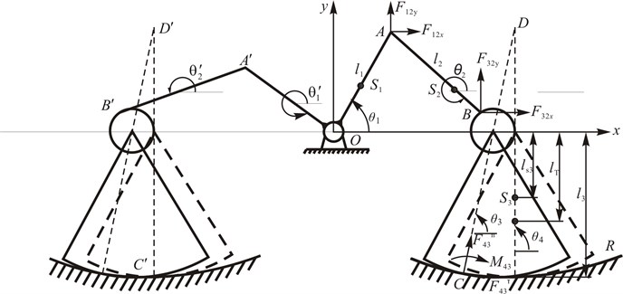
The model of low-noise excavating system with two clearances is shown in Fig. 1. The machine has two parts, and the left and right part have similar structure. For simplification, only the right side is considered. is crank and is cutter head. There are clearances at , between the crank and connecting-rod, and , between the connecting-rod and cutter head. are the length of crank, connecting-rod and cutter head, respectively, is the distance from fixed point to contact point when the cutter head is at the equilibrium position. are the mass of crank, connecting-rod and cutter head, respectively. are the mass center of crank, connecting-rod and cutter head, respectively. and are the rotational inertia of crank about fixed point and mass center, respectively, and are the rotational inertia of connecting-rod and cutter head about mass center. The torque of crank is , and the crushing torque between crushed body and cutter head is , the torsion induced by the distortion of spring in tangential direction is . are the angular of crank and connecting-rod, is angle of the engagement line of cutter head and crushed body, is the angle of the centre line of cutter head. The curvature radius of crushed body is . are the projection of mass center of connecting rod in and directions, the distance from shaft pin to shaft sleeve at is , and at .
Fig. 1Model of excavating system with two clearances
Choose as generalized coordinates, and as the origin of the coordinates, are the projections of distance between shaft pin and shaft sleeve in and direction. According to the geometrical relation, is expressed as follows:
When the distance between shaft pin and shaft sleeve is smaller than the clearance , the shaft pin does not contact the sleeve, that is, the free state; otherwise, when is larger than the clearance , the shaft pin contacts the sleeve and the system is in contact. The criterion is that:
The connected angle can be determined by:
At the contact point, the relative velocity of shaft pin relative to craft sleeve in normal and tangential direction is that:
The nonlinear contact force according to Hertz modeling is that [12, 13]:
where:
where are the contact forces at pair and in normal and tangential direction, respectively. are the stiffness coefficient, damping coefficient and friction coefficient in normal direction in normal and tangential direction, respectively.
The projections of contact force at pair in and direction are that:
The projections of contact force at pair in and direction are that:
Now the motion relationship, contact and force relationship are obtained.
The dynamical equations can be established according to d’Alembert’s principle. By substituting the expressions of clearance and forces in formula (1)-(13) into dynamical equations, the motion equations are obtained. Motion equation of crank is as follows:
The dynamic equations of connecting-rod are that:
The dynamic equation of cutter head is that:
where:
Formula (19) is used to determine the direction of crushing torque .
Formula (20) is used to determine the direction of torque . The crushing torque can not be measured by experimental method, but it can be estimated through the transfer efficiency and power. The low-noise excavating system is nonlinear dynamic system with 5-dof.
3. Results and discussions
According to the sample machine, the parameters of each part in excavating system are as follows: The numerical simulation results in different conditions are obtained.
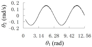
When the crank rotate with speed , and the model is Hertz contact modeling, the results are obtained when the friction coefficients in tangential direction is and , shown in Figures 2 and 3.
It can be seen from Figures 2 and 3 that when the friction increases, the vibration amplitude of crank at mass center is increased, and the high frequency component will appear.
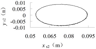
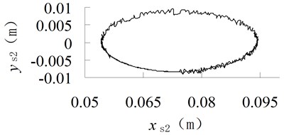
Fig. 2Trajectory of the mass center of connecting-rod with different friction coefficient
a) 0
b) 0.05
Fig. 3Angular curve of connecting-rod with different friction coefficient
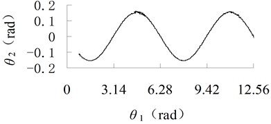
a) 0
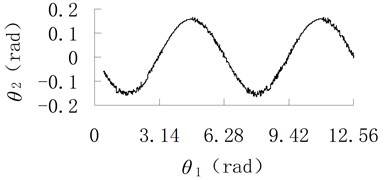
b) 0.05
Fig. 4Angular velocity curve of connecting-rod with different friction coefficient
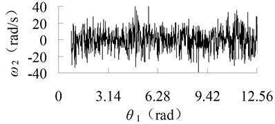
a) 0
b) 0.05
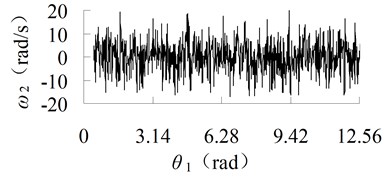
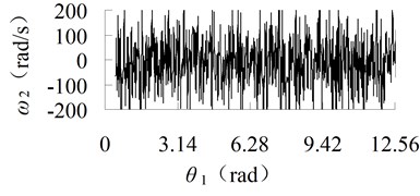
The angular velocity curve of connecting-rod is also calculated, as shown in Figure 4. It can be seen from Figure 4 that, when 0, the maximum angular velocity is rad/s, but when 0.05, the maximum angular velocity is 90 rad/s. Therefore, the angular velocity increases with the increasing of friction coefficient. To reduce the vibration, lubrication is needed.
When the crank rotates with angular velocity 15.6 rad/s, and the friction coefficient 0.01, given the size of clearance as 0.01 mm and 0.5 mm, the responses are obtained, as shown in figures 5 and 6, respectively.
It can be seen from Figures 5 and 6 that, the trajectory of the mass center of connecting-rod is ellipse, when the size of clearance increases, the shape of trajectory do not change, but the curve becomes non-smooth, the vibration is obvious.
Fig. 5Trajectory of the mass center of connecting-rod with different clearance size
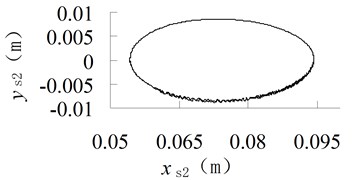
a) 0.01 mm
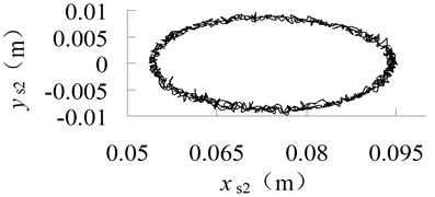
b) 0.5 mm
Fig. 6Angular curve of connecting-rod with different clearance size
a) 0.01 mm
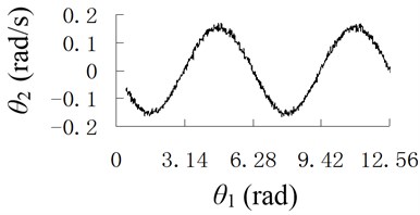
b) 0.5 mm
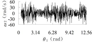
Fig. 7Angular velocity curve of connecting-rod with different clearance size
a) 0.01 mm
b) 0.5 mm
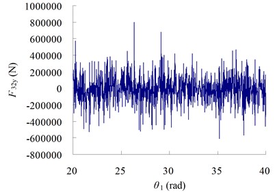
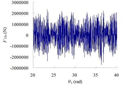
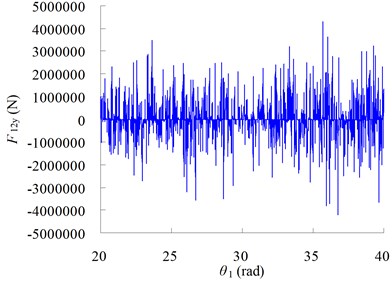
The angular velocity of connecting-rod is also obtained, shown in Figure 7. It can be seen that, when the size of clearance becomes larger, the angular velocity will become larger, the maximum velocity change from to , and the impulse is more serious. The curves of load torque and contact force are shown in Figure 8.
Fig. 8Force curves with different angular velocity
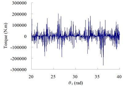
a) Torque
b)
c)
d)
The results in Figure 8 show that, when the size of clearance is large, there is very large contact and load torque in the system, the impact phenomena is obvious, which may cause noise and bring breakage to system.
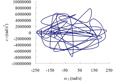
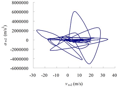
From the curves in Figure 9 we can see that, the existing of clearance will also affect the motion of system and decrease the precision of motion mechanism.
Through the calculation and analysis, it is obvious that, when the friction in clearance becomes larger, the vibration will be violent. In the design and manufacture, the precision should be improved to reduce the clearance and friction; in the optimization of system structure, the clearance can not be omitted, and the two clearances should be considered.
Fig. 9The relation curves between velocity and acceleration
a) Curve between and
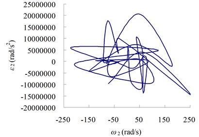
b) Curve between and
c) Curve between and
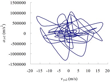
d) Curve between and
4. Conclusions
In this paper, the clearance is expressed with Hertz law, the dynamic response of excavating system with two clearances is analyzed with numerical simulation, and the effects of the size of clearance and the coefficient of friction are discussed, respectively. The numerical results show that, when the friction coefficient and the size of clearance increase, the shape of trajectory of mass center of connecting rod do not change, but the vibration is obvious, the angular velocity will become larger, which leads to the larger impact force and load torque, and brings breakage to system structure. In the design and manufacture, the precision should be improved to reduce the clearance and friction; in the optimization of system structure, the clearance cannot be omitted, and the two clearances should be considered.
References
-
V. Parenti-Castelli, S. Venanzi Clearance influence analysis on mechanisms. Mechanism and Machine Theory, Vol. 40, Issue 12, 2005, p. 1316-1329.
-
Imed Khemili, Lotfi Romdhane Dynamic analysis of a flexible slider–crank mechanism with clearance. European Journal of Mechanics A/Solids, Vol. 27, Issue 5, 2008, p. 882-898.
-
Ming-June Tsai, Tien-Hsing Lai Accuracy analysis of a multi-loop linkage with joint clearances. Mechanism and Machine Theory, Vol. 43, Issue 9, 2008, p. 1141-1157.
-
A. L. Schwab, J. P. Meijaard, P. Meijers A comparison of revolute joint clearance models in the dynamic analysis of rigid and elastic mechanical systems. Mechanism and Machine Theory, Vol. 37, Issue 9, 2002, p. 895-913.
-
P. Flores, J. Ambrosio, J. C. P. Claro, H. M. Lankarani, C. S. Koshy A study on dynamics of mechanical systems including joints with clearance and lubrication. Mechanism and Machine Theory, Vol. 41, Issue 3, 2006, p. 247-261.
-
K. Hu, Z. P. Mourelatos, N. Vlahopoulos Computational analysis for dynamic response of a rotating shaft on flexible support structure with clearances. Journal of Sound and Vibration, Vol. 267, Issue 1, 2003, p. 1-28.
-
Eleonor D. Stoenescu, Dan B. Marghitu Dynamic analysis of a planar rigid-link mechanism with rotating slider joint and clearance. Journal of Sound and Vibration, Vol. 266, Issue 6, 2003, p. 394-404.
-
P. Metallidis, S. Natsiavas Vibration of a continuous system with clearance and motion constraints. International Journal of Non-Linear Mechanics, Vol. 35, 2000, p. 675-690.
-
P. Flores, J. Ambrosio Revolute joints with clearance in multibody systems. Computers and Structures, Vol. 82, Issue 1, 2004, p. 1359-1369.
-
Jungkeun Rhee, Adnan Akay Dynamic response of a revolute joint with clearance. Mechanism and Machine Theory, Vol. 31, Issue 1, 1996, p. 121-134.
-
Chang Zongyu, Wang Yuxin, Zhang Ce Chaotic behavior in linkage with a clearance. Mechanical Science and Technology, Vol. 17, Issue 3, 1998, p. 245-348, (in Chinese).
-
Ali Azimi Olyaei, Mohammad Reza Ghazavi Stabilizing slider-crank mechanism with clearance joints. Mechanism and Machine Theory, Vol. 53, Issue 7, 2012, p. 17-29.
About this article

This work is supported by the National 863 Plans Project (Grant No. 2007AA04Z209), the National Natural Science Foundation of China (Grant No. 51009107), Tianjin Natural Science Foundation (Grant No. 13JCQNJC04200 and 13JCZDJC27100).
