Abstract
In the overall study of the design and performance of the lunar Lander, analysis of touchdown dynamics of the landing stage is an important part. In this paper, the influence of the lunar Lander’s body deformation on the landing performance is studied. First, the equations with the flexible part are derived from the subsystem method and deducing a multi-mass model by comparing and analyzing the mode of the body in Lander. Second, based on the existing aluminum honeycomb buffering and the model used in the landing-impact tests for the soft-landing system, a finite element model for the cantilever-type landing gear with four legs is established in MSC.Patran and submitted to MSC.Dytran to conduct a simulation analysis. Finally, the flexibility of lander’s body to the performance in landing is studied. Results show that the deformation of the body has considerable effect on the overloading of the lunar Lander system though the deforming can absorb litter energy during landing.
1. Introduction
Soft-landing system is an important technology for planets exploration. During the first critical seconds of touchdown, the landing gear system must absorb the kinetic and potential energies of the vehicle without causing the lunar Lander to topple and must attenuate the landing loads to prevent damage to the spacecraft during the landing impact and to bring it to rest in an upright attitude so that no part of its mission such as deployment of instrument or re-launch will be inhibited. At present, the research in this area of lunar lander mainly focuses on the lander concept [1-3], cushioning property [4-5], dynamic analysis [6-10] and stability analysis [11-15]. For the design of soft-landing system in lander, the two-mass simplified model is very common used in preliminary work and verification for landing performance of the soft landing buffering system. Based on the system model, this paper presented the numerical simulations of soft-landing and conducted a simulation of the landing impact response based on the finite element model of nonlinearity. Then the research on the flexible deformation of the lander’s body to the landing performance is conducted [16-17].
2. The simplification of the lander body taking deformation into account
2.1. Model of the soft landing system
In order to meet the functional requirement of soft- landing gear system, and make the buffer work stably and reliably, the four-leg suspension landing buffer with aluminum honeycomb absorbing energy would the best model according to the features of different soft-landing gear system and the requirement of the lunar exploration program of China Change’s Project.
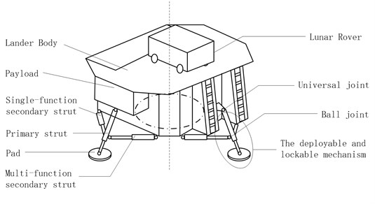
As Fig. 1 shows, every landing leg consists of three parts. They are four groups of main buffer leg (primary strut), auxiliary buffer struts (secondary strut) and footpad. It is the universal joint who makes the primary strut and secondary strut connect to the body of the landing gear system. The secondary strut and the primary strut are connected by ball joint, and it is the same to the primary strut and footpad. The deployable and lockable mechanism is settled at the inner of one of secondary strut of every group, which should be called multi-functional secondary strut. Another secondary strut is made up by tensile buffer aluminum honeycomb, compression buffer aluminum honeycomb band piston rod, and the inner structure of the strut is similar with multi-functional secondary strut. Without deployment and locking mechanism, it is just used for buffering, so it is called single functional secondary strut [18].
Fig. 1Schema of soft-landing gear mechanism
2.2. Multi-mass model analysis
Equation for the analysis were developed corresponding to the two-dimensional touchdown dynamics model shown in Fig. 2. This model is adequate for the analysis of either three or four legged vehicle. Motion takes place in a plane such that two legs contact the surface simultaneously for four-legged vehicle. It is assumed that the vehicle has feet of sufficient area to prevent penetration of the lunar surface [19]. In this model, the lander body is simplified to a simple mass - spring system based on the rigid mode of structure vibration motion and first n dynamics equations of vibration modes of a lunar Lander, which module quality and the number of spring depends on the order of flexible modes and accuracy requirements of system [20]. The simplified model of lander body model analysis and the body equivalent principle are as follows:
1) The natural vibration frequency of the simplified model and the actual modal frequencies of the lander body are the same.
2) The vertical response of the intersection of simplified model / buffer system and the landing / buffer system are the same under the same load.
Fig. 2Simplified model of the lander body modal analysis
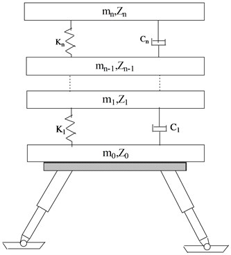
Where in Fig. 2:
– simulation of th order modal mass of lander,
– simulation of th order modal spring stiffness of elastic effect,
– the vertical displacement of the mass ,
– simulation of th order modal flexible damping coefficient.
Based on the rigid mode of the lander structure vibration and the order dynamic equation of the vibration mode the dynamic equation is:
where , , .
The dynamic equation of lander body in modal coordinates (include rigid mode) is:
where .
Corresponding lander sinking mode with unit vertical displacement:
– generalized mass diagonal matrix,
– generalized stiffness diagonal matrix,
– modal damping coefficient diagonal matrix.
According to the former equivalence principle, there is:
Let:
Thus:
where:
Put equation (6) into (1), collated as:
Compare formula (2) with formula (7), the right options are found identical. The equivalent condition of the simplified model and the original lander body attribute to the coefficient matrix of the formula (2) corresponding to the formula (7) in the left:
Undetermined coefficients , parameters , and in the simplified model can be determined in equation (8). Since and satisfying the conditions that , ensuring the free vibration frequency of the simplified model with the original landing body are consistent.
3. The finite element model and the simulation analysis of landing performance
3.1. The finite element model of the wholly landing simulation
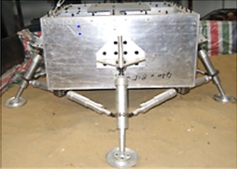
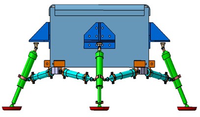
The finite element of the soft-landing system is created by simplifying the related apparatus, as shown in Fig. 3, this model is designed by Nanjing Astronautics and Aeronautics University. The soft-landing system includes the main strut, the secondary strut, the buffering, the footpad and the compression release apparatus [20-22]. The main strut is equipped with the buffering which can relieve the landing impact. The secondary strut is equipped with the stretching and locking apparatus which is used to stretch and lock before impact. The compression release apparatus achieves to compress and release the footpad which can avoid excessive subsidence and relieve the sliding resistance. Because the landing leg is composed of honeycomb whose wall thickness is far less than its length, the cylindrical shells can be simplified as the shells unit and the collector as the mass unit and the footpad as the shells unit [23-24]. The shells unit is divided as grids with QUAD4. The piston rod and the outer cylinder of the landing leg is made up of aluminum alloy 7A09T6 whose performance parameters (density, elastic modulus, Poisson’s ratio) are given by: , , . The static friction coefficient, the dynamic friction coefficient and the exponential decay coefficient of the aluminum alloy are given by: , , . After connecting every member and defining the touching if the aluminum honeycomb is equivalent to the Lagrange unit Hex8, the finite element model of the prototype is divided as: units, connectors, as shown in Fig. 4.
Fig. 3Schema of landing gear system
a)
b)
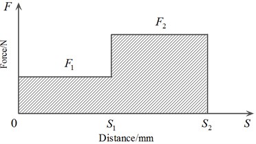
The buffering is composed of the strong aluminum honeycomb and the weak aluminum honeycomb. As shown in Fig. 5, the resilient section and the dense segment of the honeycomb are small after simplification. Assuming the carrying capacity 16.4 kN, 35.4 kN.
Then we have the corresponding buffering stroke 150 mm, 300 mm.
Fig. 4Finite element model for soft-landing impacting
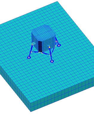
Fig. 5Undergone sketch of the two-stage honeycomb buffering
3.2. Simulation analysis of landing performance
In this paper, the landing conditions are set as follows: the value of the gravitational field acceleration is , the lander is released vertically from the origin at the speed of and its four legs land on the ground at the same time, the module on the landing performance is rigid, the total mass is .
Acceleration response and buffering stroke are the basic evaluation for the honeycomb during the landing. In order to reduce the influence of high-frequency response, fast Fourier transform is used to do frequency spectrum analysis of the original data. At the same time, we adopt a series of low-pass filters of frequency of which is processed for it. Fig. 6 represents simulation curves of the lander’s acceleration response which has been processed by a series of low-pass filters.
Fig. 6Acceleration time histories of lunar landing
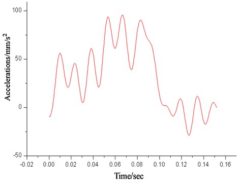
Two-stage aluminum honeycomb buffering apparatus is adopted by primary buffering, as shown in Fig. 7. The primary aluminum honeycomb is compressed in , when the value of acceleration remains about . In , the acceleration increases dramatically and then to its peak value of , in the value of acceleration oscillates around , and then the secondary aluminum honeycomb comes into play. In , the lander reduces its acceleration rapidly to finish the process of landing until its value oscillates around and attitude tends to stabilize. Throughout the process of landing impact, the fluctuations of acceleration response are mainly caused by buffer and the dynamic response of structures, where the response higher than has been filtered.
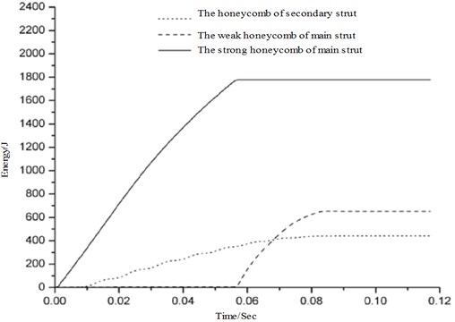
The cushioning effect of the main and secondary buffering is mainly reflected on absorption of aluminum honeycomb to impact energy during the landing. As shown in Fig. 7, the weak aluminum honeycomb on main and secondary buffering begins to work from ; at , energy absorption capacity of weak aluminum honeycomb is depleted. At the same time, the strong aluminum honeycomb begins to work. As a result, the intensity of lander’s acceleration response increases. It is not until the aluminum honeycomb on main and secondary buffering finish stopping the service that the value of lander’s acceleration response starts to decrease rapidly.
Fig. 7The energy absorption of main and secondary honeycomb
4. Flexible dynamics model analysis of the body in lunar lander
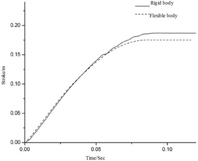
Soft-landing buffering is an important apparatus that to used to absorbing energy when landing on the ground. In the process of landing, the lander body will endure the corresponding elastic-plastic deformation. Bibliography [19] constructed a rigid-flex coupling dynamic model of the rigid landing leg. Meanwhile, it analyses the effect of lander body distortion to the landing performance. In that paper, the author points out that the body's flexible deformation will be harmful to landing performance when landing. This section presents a study of the effect of lander body distortion to landing performance in flexible state. Now we set the body as rigid and compare the simulation results with the flexible ones, the results as shown in Fig. 8-9.
As mentioned above, there is a very substantial increase in the maximum structure responses of acceleration and the cushioning strake comparing with the ones which doesn't take the body's flexible deformation into account. In addition with regard to the acceleration response curve with substantial and rectilinear oscillations, its amplitude relates to the elastic deformation of the body. The lander body deformation is able to absorb some of the landing impact, which is equivalent to the primary buffer apparatus. Thus reducing the efficiency of the buffer or rather making the buffer cannot absorb enough energy at the early stage. This part of energy is stored as the elastic potential energy and it will be released during the landing later. Furthermore, because flexible deformation of the body changes lander and the corresponding connection of the buffer pillar position, the maximum structure responses of acceleration and the main column stroke is larger than the case when the body is rigid. This process is periodic, so circle oscillation comes into being.
Fig. 8Comparison of the vertical acceleration as a function of time
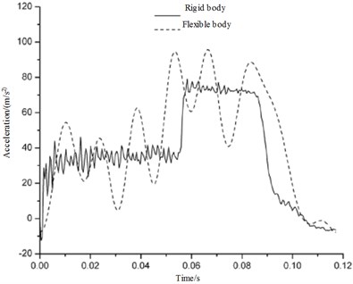
Fig. 9Comparison of the secondary strut deformation as a function of time
5. Conclusions
(1) Muti-mass equivalent model is deduced in this papers based on the simplified criterion of the lander body.
(2) The flexibility of the body has significant influence on the overloading response of the lunar lander though honeycomb cushioning material absorbs the same energy. The more flexible is the lander body, the greater is the overloading response of lander.
(3) Taking the flexible lander body into consideration when designing the soft-landing system, it is necessary to increase the structural rigidity.
References
-
Chen Jinbao, Nie Hong, Zhao Jincai Review of the development of soft landing buffer for lunar explorations. Journal of Astronautics, Vol. 29, Issue 3, 2008, p. 731-735.
-
Jon A. L., John C. Lunar Lander Conceptual Design. NASA, 1989, p. 51-58.
-
George W. Botbyl Final Design Report for the Self-Unloading, Reusable, Lunar Lander Project. B&T Engineering, 1991, p. 29-33.
-
Wang Shaochun, Deng Zongquan, Hu Ming Experimental investigation on mechanical property of metal rubber used in lunar lander in high or low temperature. Journal of Aeronautical Materials, Vol. 24, Issue 2, 2004, p. 53-56.
-
Zhao Jingdong, Wang Jinchang, Zhao Zhijun, Jiang Li, Cui Pingyuan Research on buffer of asteroid lander on semi-active control. Journal of Vibration and Shock, Vol. 29, Issue 8, 2010, p. 78-80.
-
Lu Yuntong, Song Shunguang, Wang Chunjie, Zeng Fuming Dynamics analysis for lunar lander based on rigid-flexible couple model. Journal of Beijing University of Aeronautics and Astronautics, Vol. 36, Issue 11, 2011, p. 1348-1352.
-
Wiliam C. Thompson Dynamic Model Investigation of the Rough-Water Landing Characteristics of a Spacecraft. AIAA Paper: 67-23281, 1967.
-
Wang Shao-Chun, Deng Zong-Quan, Gao Hai-Bo Design of impact isolating landing legs for micro-miniature lunar lander. Journal of Harbin Institute of Technology, Vol. 36, 2004, p. 180-182.
-
Hu Yabin, Sun Yi Research on static of lunar lander with legs. Chinese Space Science and Technology, Vol. 23, Issue 2, 2009, p. 18-26.
-
Robert E. Lavender Monte Carlo Approach to Touchdown Dynamics for Soft Lunar Landing. NASA-TN-D-3117, 1965.
-
Su Qinghua, Zhao Yan Analysis method for lunar landers landing safety. Journal of Beijing University of Aeronautics and Astronautics, Vol. 38, Issue 11, 2012, p. 1522-1526.
-
Luo Chang Jie, Deng Zongquan, Liu Rongqiang, Wang Chuang Landing stability investagation of legged-type spacecraft lander based on zero moment point theory. Journal of Mechanical Engineering, Vol. 46, Issue 9, 2010, p. 38-45.
-
Long Lvbo, Qing Qixiang, Wen Guilin, Jiang Sheng Simulation analysis of lander soft landing’s stability on ADAMS. Journal of Engineering Design, Vol. 17, Issue 5, 2010, p. 334-338.
-
Deng Zongquan, Li Kui, Liu Rongqiang, Jiang Shengyuan Influence of rover unloading on lunar lander stability. Acta Aeronautca Et., Vol. 32, Issue 12, 2011, p. 2318-2326.
-
Zhu Shengying, Cui Pingyuan, Cui Gutao, Shao Wei Autonomous position and attitude determination for interplanetary lander based on landmark observation angles. Acta Aeronautica Et., Vol. 32, Issue 2, 2010, p. 318-326.
-
Tung C. C., Penzien T., Horonjieff R. The Effect of Runway Unevenness on the Dynamics Response of Supersonic Transport. NASA-CR-119, 1964.
-
Mu Rangke, Luo Junjie Effect of aircraft structure flexibility on the shock-absorber behavior of landing gears. Journal of Aeronautics, Vol. 16, Issue 2, 1995, p. 205-208.
-
Qin Lin, Hong Nie, Jie Ren, Jinbao Chen Investigation on design and reliability analysis of a new deployable and lockable mechanism. Acta Astronautica, Vol. 73, 2012, p. 183-192.
-
Chen Jinbao, Nie Hong Overloading of landing based on the deformation of the lunar lander. Chinese Journal of Aeronautics, Vol. 21, Issue 1, 2008, p. 43-47.
-
Zhu Wang, Yang Jian-Zhong Modeling and simulation of landing leg for the lunar landing. Journal of Astronautics, Vol. 29, Issue 6, 2008, p. 1723-1728.
-
William F. R. Apollo Experience Report 2, Lunar Module Landing Gear Subsystem. NASA TN D-6850, 1972.
-
Deng Zong-Quan, Wang Chuang, Gao Hai-Bo, et al. The research situation of lunar lander. Missles and Space Vehicles, 2006, p. 33-34.
-
Herr Roberrt W., Lconard H. Waync Dynamic Model Investigation of Touchdown Stability of Lunar Landing Vehicles. NASA TN D-4215, 1967.
-
Ulysses Blancha Full-Scale Dynamic Investigation of a Prototype Lunar Module. TN D5029, 1979, p. 1-41.
About this article

The authors are grateful to Prof. Nie Hong for discussions and Bo Wei for providing helps. The authors would also like to thank the anonymous reviewers for their critical and constructive review of the manuscript. This study was co-supported by the NUAA Fundamental Research Funds (No. NS2013086).
