Abstract
A new method for suppressing vibration in a rotating beam system of a helicopter is presented. The method uses a non-linear dynamics equation to compute actual natural frequencies using FFT, not based on nominal natural frequencies of linear dynamics. A design based on linear coupling may not take account of the effect of non-linear coupling in the system, so a conceptual controller design is also presented, and a detailed control algorithm is developed. In fact, this is a non-linear dynamics optimization problem.In a gyroscopic system, tuning of the flywheel allows a commensurable relationship to be established between the natural frequencies of the system, resulting in a strong coupling between the vibrating modes. Having established a strong coupling within the system, damping is introduced in the flywheel via an actuator, resulting in rapid vibration suppression. Numerical simulation demonstrates the efficiency of the modification.
1. Introduction
Gyroscopic coupling arises naturally in many types of system. The purpose of this paper is first to establish a strong coupling by tuning of the flywheel that allows a commensurable relationship between the natural frequencies of the non-linear gyroscopic system, and then to suppress vibration by velocity feedback. The focus is on a particular type of gyroscopic system-the rotor. Some examples of rotors are: helicopters, propellers, wind turbines, turbo machinery, auto gyros, flexible manipulator, and vortex rings [1, 8-9].
Controlling a multi-degree of freedom dynamic system normally requires an actuator for each degree of freedom. However, if the oscillations in one mode are strongly coupled to the remaining main modes in the system, an actuator applied in one direction can directly regulate vibrations in that mode and indirectly in the remaining modes. Normal gyroscopic coupling in rotors is usually not strong enough to accomplish such a task. However the system can be tuned to make the coupling strong and then damping can be introduced in one of the modes resulting in vibration suppression in all the coupled modes.
Coupling in a system can be strengthened using Internal Resonance (IR). Internal resonance is established by making natural frequencies in the system commensurable. In studies conducted by Golnaraghi [1, 2], a sliding mass was used to introduce non-linear coupling and to control vibrations in a flexible cantilever beam. By slightly damping the sliding mass motion, control was effected when the natural frequencies were tuned to a state of 2:1 IR. Experimental investigations were conducted by Tuer et al. [3] and Duquette et al. [4] using a flexible cantilever beam, further reinforcing results resorted in [1, 2].
The motivation for this paper stems from an earlier work [5, 6], in which a discrete flexible two-degree of freedom cantilever beam is rotated at a constant angular velocity about the vertical axis. It was shown in [5, 6], numerically and using a perturbation method, that IR can be used to suppress vibrations in gyroscopic systems. This however required modifying the physical characteristics of an existing system, which may not be always possible.
To make the application of IR-based vibration suppression more practical, and to accomplish this without tuning any existing stiffness in the system, in this paper we present a tunable flywheel mechanism. The tunable flywheel mechanism attaches to the rotating axis of the rotor. The coupling in the system can then be enhanced by tuning the flywheel mechanism and does not require modifying any existing stiffness in the system.
In this paper, equations of motion are derived for an idealized model of a rotating beam with the tunable flywheel mechanism. The rotating beam’s angular velocity is allowed to vary about an equilibrium value. The angular velocity and gyroscopic effects non-linearly couple the flywheel with the rotating beam. Using a simple linear control scheme, like a PD controller on the flywheel, allows an IR based control strategy to be implemented. The flywheel is tuned such that a 1:1 state of IR is established, thereby, aiding in the transfer of vibrational energy between the flywheel and the beam. Damping introduced in the flywheel dissipates the energy from the system, thus suppressing vibrations. Application of this strategy is verified through numerical simulations. The numerical simulations show that rapid vibration suppression occurs in the system.
2. Mathematical model
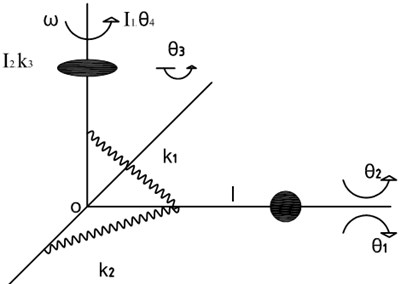
The system model is shown in Figure 1. The model is an idealization of a flexible beam of length and mass , attached to a rotating shaft. The flexibility of the beam is model using linear rotational springs of stiffness and in the vertical and horizontal planes respectively.
Fig. 1System model
Equations of motion are obtained by the Lagrangian approach using the following non-dimensional parameters:
In (1), is moment of inertia, represents constant average angular velocity of the rotating shaft. The on the variables indicate a non-dimensional quantity. In the rest of the paper only non-dimensional parameters are used, therefore for convenience the is dropped. The non-dimensional rates for , , and are denoted as , , , , , , , and , where the and represent first and second derivatives with respect to non-dimensional time, respectively.
Using standard techniques, the following expressions are obtained for the kinetic energy and potential energy of the system:
Here we note that each term in (2) is multiplied by a constant factor that is obtained when non-dimensionalizing. Since this factor divides out from the final equations of motion it is not shown in the energy terms.
Using the system energies we get the Lagrangian as:
Using the Lagrangian method the following non-dimensional equations of motion are obtained:
In (4), , and are actually transformed variables , and , where the asterisks have been dropped as we will be using the transformed variables from this point in the analysis. The transformation is given by:
where represents the constant part of the angular velocity of the shaft.
Also in (4), the control torque has been incorporated by redefining as .
This represents tuned natural frequency of the flywheel.
3. The parameter optimization algorithm
The strength of the technique for vibration suppression depends upon how strong the coupling can be made between the different degrees of freedom. When 1:1 IR is used for enhancing the coupling we are relying upon enhancing the linear coupling in the system. When the coupling in the system is predominantly non-linear then 1:1 ratio may not work and other approaches such as 1:2 and 1:3 are required depending upon the type of non-linear coupling [7]. So a design method based on linear coupling does not take effect to non-linear coupling in the system. Now we present a new following design method based on an actual non-linear system.
Optimization index:
where , are the nature frequencies. is tuning parameter. is the ratio of to for setting up 1:1 IR, 1:2 IR and 1:3 IR.
Rewrite above eq. (6) into following form:
4. IR suppression control strategy
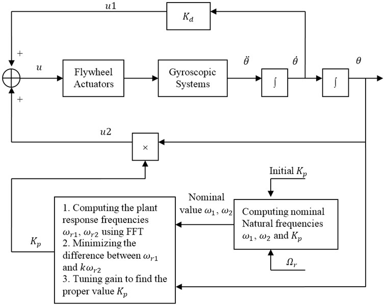
In this section, the optimization algorithm of IR control strategy is presented first. The principle of control is shown in Figure 2. The actuator is a tunable flywheel.
The control law is shown in Figure 2. Control variable is summation of and .
Control: .
shows the control efforts applied to the non-linear gyroscopic system using D feedback control technique based on IR state. The control signal to the system is issued in the form of force by the tunable flywheel. The accelerometer can be used to measure the output acceleration . By integrating once the corresponding velocity can be obtained. Here velocity feedback (D controller) is sent to the actuators to suppress vibrations in all the three directions. Finally, integrating can give us the displacement that can be used as the displacement feedback (P controller) to the actuator and as input to compute the response frequencies of the non-linear gyroscopic system.
indicates the tuning process for obtaining P gain and establishing IR state as well. Taking an assumed and angular velocity as input, it first computes the 2 nominal natural frequencies of the (linear gyroscopic system) gyroscopic system around the equilibrium point . Meanwhile the computer also takes the displacements as input signals and computes the real response frequencies of the non-linear gyroscopic system using FFT, which contains many frequencies. In the vicinity of the two nominal natural frequencies, the computer will choose the two dominant real response frequencies , and compute the difference between and , where is IR ratio ( for 1:1 IR and for 1:2 IR, etc.). By minimizing the difference between and , the computer can thus tune and use the updated as input to compute the new nominal natural frequencies. At the same time, the can serve as the P gain in gyroscopic system to obtain new displacement . Using this new as input, the computer can compute the new real response frequencies of the gyroscopic system. The above iteration process goes on until the difference between and is minimized and the IR state is thus established. Then through u1 velocity feedback control involved in the gyroscopic system, the vibration in , and directions can be effectively and rapidly suppressed.
Fig. 2Control law using IR. θ is displacement vector, Ωr stands for angular velocity
Optimization algorithm for the control law is as following:
Step 1: Setting initial value , IR ratio ( for 1:1 IR and for 1:2 IR, etc.), parameter and .
Step 2: Computing the nominal natural frequencies and .
Step 3: Computing the plant response frequencies , by using FFT.
Step 4: Computing the difference between and , and get the parameter:
.
Step 5: Turning gain slightly by using follow computation:
.
Step 6: Minimizing the difference between and .
If is the minimum, the optimum gain is obtained, and go to Step 7. Else go to Step 2.
Note: is a very small positive coefficient.
Step 7: Computing the control variables and .
Step 8: Summation of control variables .
5. Vibration suppression simulation
As was mentioned earlier, suppression of vibrations within all the degrees of freedom is accomplished by applying a linear actuator in the direction. The actuator applies direct damping to , and tunes the value of through position feedback by applying a torque of the form . Tuning is accomplished by adjusting the feedback gain .
Coupling between motion in , and directions is enhanced by establishing an internal resonance ratio of 1:1 between the natural frequencies. In this gyroscopic system, natural frequencies , can be tuned to be equal to or , is selected as the value that minimizes the difference between or .
Fig. 3Output θ1 time response: ωn1=2, ωn2=5, Ωr=5, T1c=0, C=1.5
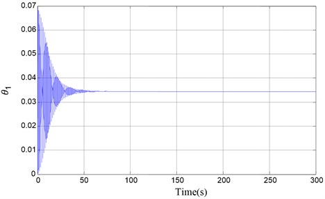
Fig. 4Output θ2 time response: ωn1=2, ωn2=5, Ωr=5, T1c=0, C=1.5
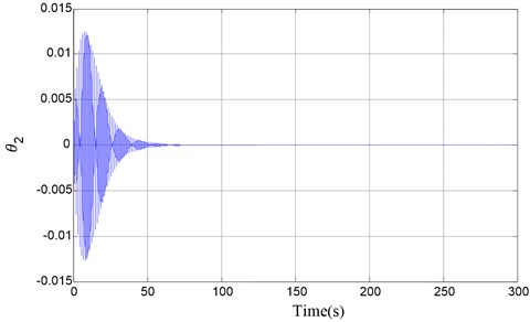
Fig. 5Output θ3 time response: ωn1=2, ωn2=5, Ωr=5, T1c=0, C=1.5
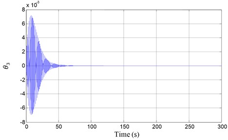
We show the results of vibration suppression using numerical simulations of the non-linear dynamics equations of motion (4). The vibration control principle frame is shown in Figure 1. Its displacement output vibrations in all the degrees of freedom are suppressed as shown in Figure 3, Figure 4 and Figure 5.
Variation of the system parameter leads to equilibrium positions change. The specific value for parameters in figure is determined by equilibrium points. With the help of MATLAB software, computation simulation of the system model is made. The result of simulation demonstrated that parameter optimization and active vibration suppression control integration techniques that we presented in gyroscopic system are practical, and there are good vibration suppression performance.
6. Conclusions
This paper presents a new method to implement an internal resonance based vibration suppression technique for a multi-degree of freedom gyroscopic system. The technique is based on enhancing the natural gyroscopic coupling that exists in the system via Internal Resonance. The principle of a controller design is presented, and detail control algorithm is developed. At the same time, the concept of a tunable flywheel mechanism has been also proposed. The advantage of this approach is that it does not require modifying any existing stiffness in the system either directly or through any control mechanism. It was demonstrated numerically how the tunable flywheel mechanism can be used for vibration suppression. The modifications that can be made for application of the proposed technique for vibration suppression to more complex models is the use of nonlinear techniques to enhance the existing coupling in the system. This is a new highlight.
References
-
Golnaraghi M. F. Vibration suppression of flexible structures using internal resonance. Mechanics Research Communications Journal, Vol. 18, Issue 2-3, 1991, p. 135-143.
-
Golnaraghi M. F. Regulation of flexible structures via nonlinear coupling. Journal of Dynamics and Control, Vol. 1, Issue 4, 1991, p. 405-428.
-
Tuer K. L., Duquette A. P., Golnaraghi M. F. Vibration control of a flexible beam using a rotational internal resonance controller, Part I: Theoretical development and analysis. Journal of Sound and Vibration, Vol. 167, Issue 1, 1993, p. 41-46.
-
Duquette A. P., Tuer K. L., Golnaraghi M. F. Vibration control of a flexible beam using a rotational internal resonance controller, Part II: Experiment. Journal of Sound and Vibration, Vol. 167, Issue 1, 1993, p. 63-75.
-
Siddiqui A. Q., Golnaraghi M. F. Vibration suppression in a flexible gyroscopic system using modal coupling strategies. Journal of Mathematical Problems in Engineering, Vol. 2, Issue 2, 1996, p. 107-129.
-
Siddiqui A. Q., Golnaraghi M. F. A new vibration regulation strategy and stability analysis for a flexible gyroscopic system. Journal of Sound and Vibration, Vol. 193, Issue 2, 1996, p. 465-481.
-
Stupnicka W. On the phenomenon of the combination type resonance in nonlinear two-degree of freedom systems. International Journal of Non-Linear Mechanics, Vol. 4, 1969, p. 335-359.
-
Shinn-Horng Chen, Jyh-Horng Chou, Chien-Jyh Chen Robust-optimal active vibration controllers design for the uncertain flexible mechanical systems possessing integrity via genetic algorithm. International Journal of Mechanical Sciences, Vol. 50, Issue 3, 2008, p. 455-465.
-
Qiu Zhicheng, Wang Bin, Han Jianda, Wang Yuechao Vibration control of a flexible manipulator driven by a pneumatic rodless cylinder. Robot, Vol. 34, Issue 1, 2012, p. 9-16.
About this article

This research was performed under Postdoctoral Fellowship, which is funded by Canada NSERC Funds Project, Zhejiang Province Natural Science Foundation of China (LY13F030004) and National Natural Science Foundation of China (61273332).
