Abstract
Anti-backlash gear can improve the static transmission precision of system. Besides, the dynamic characteristics of anti-backlash gear system have a significant effect on the performance of overall mechanism, and assembly parameter is an important factor to affect the dynamic characteristic. In order to study the effect of assembly parameter, a single-stage anti-backlash transmission box was taken as an example. Then, the influence of assembly shrink range and preload force on bearing contact stiffness was considered, and the calculation formula of bearing radial stiffness was derived. The calculation method of anti-backlash gear composite mesh stiffness was introduced. Based on this, the transverse-torsion geared rotor-bearing dynamics model and differential equations of anti-backlash gear system with bearing contact stiffness and composite mesh stiffness were proposed. Numerical calculation and the result analysis of frequency sweep show that increasing the shrink range can increase the bearing radial stiffness and further improve the low order resonant frequency (RF) of the system; the effect of inner and outer ring on resonant frequency is equivalent, but neither is obvious. Increasing preload can enhance the bearing radial stiffness and improve the resonant frequency of the system, and the extent of the effect is greater than that of shrink range on the resonant frequency; the effect of preload force on the resonant frequency is obvious.
1. Introduction
The spring-loaded (or torsion-spring-loaded) anti-backlash gear used for controlling the return difference was invented in 1952 or earlier [1]. At present it is extensively applied in numerous fields, e.g. precision servos [2, 3], radar antennas [4] and precision machine tools. Many precision mechanisms with anti-backlash gear require the dynamic characteristics of high speed, high accuracy and high stability. Under the complex work conditions, thus, the internal excitations such as time-varying mesh stiffness, bearing stiffness have effects on dynamic performance, especially vibration characteristics of whole system, which is worth studying.
In the geared rotor-bearing system, stiffness including mesh stiffness of gear pair and axial or radial stiffness of bearing is a kind of greatly important parameter. The stability of power transmission and the dynamic performance of system depend on stiffness. As we all know, the factors such as material properties of parts, structural design and processing have an important effect on mechanism stiffness. Besides, the assembly parameters including the shrink range and preload force also have effect on the stiffness [5]. Especially, to the assembly of existing parts, adjusting the assembly parameters is important technical means to improve the dynamic performance of product.
In the recent two decades, the studies on time-vary mesh stiffness of gear pair are deep, and the research methods mainly include formula method, such as Weber-Banaschck formula and Ishikawa formula, simplified square wave method and FEM.
In the research field of rolling bearing, Harris [5] reviewed and studied the related theory systematically on the rolling bearing. The effect of shrink range on radial internal clearance was analyzed by him. Generally, in order to get a better effect of pretension, additional preload is applied to rolling bearing. In papers [5-7], pretension types, calculation of preload force and shrink range were analyzed profoundly, and some approximate calculation formulas were derived. Based on these achievements, the calculation formulas of bearing radial, axial and angular stiffness were derived on the basis of rolling bearing quasi-statics analysis theory and raceway control theory by Wang and Xia [8], considering the factors of shrink range and preload. In paper [9], the bearing dynamic stiffness/damping matrix was derived in terms of the bearing motions (displacements/rotations) and the bearing analysis considered the bearing nonlinearities, cage rotation and bearing axial preload.
Kahraman and Singh [10-11] launched a series of studies on nonlinear dynamics of geared rotor bearing system. In paper [10], nonlinear frequency response characteristics of system were analyzed using Runge-Kutta numerical integration method and harmonic balance method (HBM) respectively, and factors of gear side clearance and radial internal clearance were both considered in paper [11]. In paper [12], the effects of axial preload on nonlinear dynamic characteristics of a flexible rotor supported by angular contact ball bearings were studied, and the dynamic model of ball bearings was improved for modeling a 5 DOF rotor bearing system. Li and Ren et al. [13] proposed a multi-DOF rotor bearing model considering some nonlinear factors. In this paper, the regularity for change of instable rotation speed of geared rotor bearing as amount of bearing radial clearance and aspect ratio was mainly studied. Chen and Kang et al. [14] made some contributions to the analysis of the interactions between gears, shafts and journal bearings in a geared rotor-bearing system. In a word, there were many achievements on dynamic analysis of geared rotor bearing system, however, fewer researches considered the effect of assembly factors on bearing stiffness.
At present, however, most of studies about anti-backlash gear focus on structure design and calculations, transmission accuracy and applications. There are fewer studies that mentioned mesh stiffness of anti-backlash gear transmission and dynamics of anti-backlash geared rotor bearing system. In this field, Naoki and Masayoshi [15] proposed an approximate stiffness model of an anti-backlash with the characteristic of three segment flexible joint which was used in a manipulator. A dynamic model with friction of anti-backlash gear servomechanism by Kwon [2], and the stiffness model of anti-backlash gear were similar as three segment flexible joint characteristic. Allan and Levy [3] proposed a method for estimating the minimum preload torque required to obtain a satisfactory step response from a position control system with spring-loaded anti-backlash gear.
In summary, study on system dynamics of anti-backlash gear is rare, especially on the anti-backlash geared rotor-bearing system dynamics, although system dynamics study of ordinary geared rotor-bearing is increasingly improved. In this paper, the transverse-torsion dynamics mathematical model of a 3 DOF anti-backlash geared rotor-bearing transmission system will be proposed, considering the composite mesh stiffness of anti-backlash gear system and bearing stiffness. The effect of assembly factors, such as shrink range, radial preloaded force of bearing, and stiffness of preloaded spring, on anti-backlash geared rotor-bearing system dynamics characteristics will be emphatically studied, and some results will provide a reference or basis for further research of dynamics characteristics, optimization design and assembly performance of anti-backlash gear system.
2. Anti-backlash gear and the composite mesh stiffness
2.1. The structure of anti-backlash gear
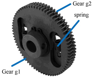
As shown in Figure 1, gear g1 is named fixed gear; gear g2 is a free gear named loaded gear. The g1 and g2 connected by two or more springs rotate relatively by an angle of some teeth, and springs are preloaded at this point, then g1 and g2 as an integral gear engage with the pinion. Two sides of a tooth of the pinion contact respectively with a tooth of g1 and a tooth of g2 under the action of spring force. Therefore, there is no backlash in transmission no matter it is in positive rotation or in reversal.
Fig. 1Structure of anti-backlash gear
2.2. The composite mesh stiffness of anti-backlash gear
The equivalent mesh stiffness of pinion and gear g1 in an anti-backlash gear is established as shown in Figure 2. In this figure , , are respectively the contact stiffness of pinion and gear g1, the contact stiffness of pinion and gear g2, and the stiffness of spring. , are respectively the composite transmission error of pinion and gear g1, pinion and gear g2; is the deformation of preloaded spring.
Fig. 2The equivalent model of anti-backlash gear mesh stiffness [16]
![The equivalent model of anti-backlash gear mesh stiffness [16]](https://static-01.extrica.com/articles/14659/14659-img2.jpg)
According to the Yang and Shang et al.’s paper [16], the composite mesh stiffness is calculated by:
where and are:
where are respectively the single-point mesh stiffness of 4 mesh points [16], and the calculation formula of mesh stiffness at point (i. e. point ) was derived by Kuang and Yang [17] as:
where is the Hertz contact stiffness per unit width [17]; is the effective tooth width with the unit of mm; is the number of tooth, ; is the bending stiffness per unit width in the line of contact [17]; is the distance between mesh point and the center of gear ; , ; is the sign function, and is angle difference between the current rotation angle and the critical angle of single-tooth mesh area to double-tooth mesh area.
2.3. Contact stiffness of bearing
In this study axial stiffness and angular stiffness of the bearing are not considered.
The problem of the tight fit of bearing and axel, bearing and bearing seat can be treated as a problem of thick cylinder. When inner ring fits tightly with solid axel, the inner ring is expanding, and the inner raceway bottom diameter is increasing. When outer ring fits tightly with bearing seat, the outer ring is shrinking, and the outer raceway bottom diameter is decreasing. Usually, the force balance equations of bearing are written as:
where , are separately the radial force and radial force generated by the normal load of ball, and:
where is the real contact angle of the th ball and raceway; is the position angle of the th ball; is the normal contact load of the th ball, and:
where is the normal contact deformation of the th ball and raceway; is the stiffness coefficient which depends on the material and shape. But for steel bearing can be calculated by:
In Eq. (7), is the curvature function, , and , are separately the principal curvature radius of two contact surfaces; the values of , , are given by Hamrock and Dowson [18] using curve fitting:
The normal contact deformation and the real contact angle of the th ball and raceway are calculated by:
where ; is the radial deformation; is the axial deformation; is the initial contact angle of bearing after interference fit and applying axial preload, and:
is the axial initial deformation after applying axial preload:
here , are separately the increment of inner raceway bottom diameter and the decrement of outer raceway bottom diameter [7]; is the bearing radial clearance; is the ball diameter; , are separately the curvature radius coefficient of inner raceway and outer raceway.
Only considering the bearing radial stiffness and under the radial load , the radial stiffness can be calculated by:
where , are separately the increment of load and deformation.
3. The 3-DOF transverse-torsion dynamics model
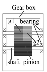
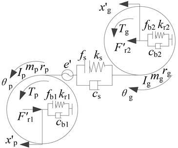
As shown in Figure 3a, this is a transmission case with one-stage anti-backlash gear transmission system. In order to establish a model with enough precision and make the model not too complex, some assumptions and conditions are given as: (1) assume that g1 and g2 work as a gear , and the pinions and are connected by a spring-damping connector as shown in Figure 3b; (2) assume that the return difference of gear is equal to zero, and the bearing clearance is considered when modeling; (3) assume that the stiffnesses of shafts are large enough, i. e. the shafts are rigid, and the axial displacements of shafts are neglected; (4) both the axial and radial load are applied to the contact bearing, and , are separately the axial and radial loads; (5) when modeling, both the low frequency external excitation caused by input fluctuation and the high frequency internal excitation caused by static transmission error are considered, and the output fluctuation is neglected; (6) no friction is considered.
According to the Newton's second law, the transverse – torsion motion differential equations of the anti-backlash gear system are written as:
and:
where stands for the full derivative with respect to time ; is the input torque; is the mean of ; is the input torque fluctuation; is the output torque; , , , are separately the transverse and torsion displacements of gears and ; is the equivalent mass of system; is the average mesh force; is the force fluctuation relative to the external input torque excitation; , , , are separately the rotary inertias and masses of gears and , and , ; , are separately the base radius of gears and ; , , , , , are separately the stiffnesses and dampings of bearing , bearing and gear transmission system; , , are separately the clearance nonlinear functions of bearing , bearing and gear transmission system.
Fig. 3Example and its dynamics model: a) gear transmission box, b) transverse-torsion dynamic model
a)
b)
The composite transmission error is defined as:
Then Eq. (13) is transformed to the matrix form as:
where , , and:
4. Numerical calculations and analysis
In order to emphasize the effect of time-varying mesh stiffness, shrink range and preload force, etc. on nonlinear dynamics characteristics of system, and considering the fact that when applying the preload force the bearing clearance decreases, in this paper the nonlinear effect caused by bearing radial clearance is neglected. In addition, assume the bearings are of the same size, though the gears are not the same.
An anti-backlash gear the parameters of which are shown in Table 1 is taken as a calculation example. The numerical calculation model is established in Matlab/Simulink with the algorithm of fifth-order Runge-Kutta and fixed-step of 0.0001 s.
Table 1Parameters of anti-backlash gear system
Parameter | Value | |
Number of teeth | 20 | 40 |
Modulus , mm | 0.6 | |
Pressure angle ° | 20 | |
Addendum circle coefficient | 1 | |
Moment of inertia , kg mm2 | 0.0515 | 0.258 |
Mass , g | 33.95 | 48.27 |
Effective face width , mm | 6.5 | |
Tooth thickness , mm | 0.8 | |
Stiffness of spring , N mm-1 | 10000 | |
Preload of torsional spring , N mm | 1000 | |
Modification coefficient | 0 | 0 |
Young's modulus , N mm-2 | 2.1E+05 | |
Poisson's ratio | 0.3 | |
Datum viscosity coefficient , Pa s | 0.04 | |
Lubricant viscosity coefficient , m2/N | 1.33E-08 | |
Initial rotation speed , rpm | 1000 | |
Drive torque , N mm | 100 | |
Load torque , N mm | 100 | |
4.1. The effect of shrink range and preload force on bearing radial stiffness
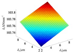
According to the calculation formulas of bearing radial stiffness and the related parameters of bearing referred to paper [9], the bearing radial stiffness is calculated and the 3-D shaded surface figures of the bearing radial stiffness functions are plotted as shown in Figure 4 and Figure 5.
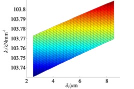
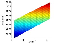
In Figure 4, and both belong to the range of [2e-3, 8e-3] mm, and the range is limited by the bearing radial clearance , according to Eq. (10). From the Figure 4, the shrink range indeed has effect on bearing radial stiffness, but the effect is not significant in this example. The bearing radial stiffness increases from 1.0373e+5 N/mm to 1.0381e+5 N/mm, as the axial and radial deformation increases from the minimum to the maximum. With the increment of shrink range both and , the bearing radial stiffness increases almost linearly with a small slope as shown in Figure 4b and Figure 4c.
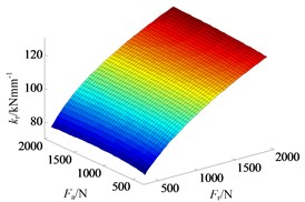
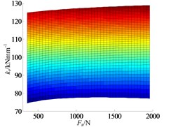
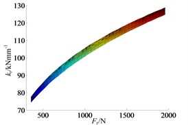
The range of axial and radial preload force is set as [400, 2000] N. As shown in the Figure 5, the axial preload force applying to bearing also has effect on bearing radial stiffness, but the effect is less than that of radial preload force. In the plane, as the increment of , the functional relation of and changes from about the parabolic to the linear, and the slope is very small. In the plane, the function relation of and is about parabolic, and the effect of to is obviously more significant than that of .
Fig. 4The effect of shrink range on bearing radial stiffness: a) ISO view, b) kr–δi plane and c) kr–δe plane
a)
b)
c)
Fig. 5The effect of preload force on bearing radial stiffness: a) ISO view, b) kr–Fa plane and c) kr–Fr plane
a)
b)
c)
4.2. Dynamic characteristics analysis of geared rotor bearing system
4.2.1. Single frequency excitation
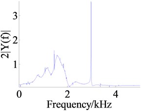
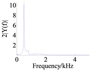
The frequency response at the single frequency excitation of 3 kHz of the geared rotor bearing system is obtained by numerical calculation as shown in Figure 7, and at this frequency excitation the curve of time-varying mesh stiffness of anti-backlash gear is plotted in Figure 8a. Figures 7a, c, e are the time domain responses of the dynamic displacements , and . From these figures the amplitude of anti-backlash gear dynamic transmission error is the largest, about 0.017 mm, and the amplitudes of dynamic displacements and are respectively about 0.8e-4 mm and 2.6e-4 mm.
The peak arises at the position of 3 kHz, which is caused by external excitation from the frequency spectrum analysis as shown in Figures 6b, d and f. In addition there are also peaks at the positions of frequency division of the external excitation, such as the position of 1.5 kHz, and under the acting of frequency division excitation, the top 3 orders of resonant frequency are exciting.
4.2.2. Frequency sweep excitation
In order to obtain the dynamic response characteristic of the system excited by the excitation of a certain frequency range, the frequency sweep analysis of anti-backlash geared rotor bearing system is completed. Frequency sweep means that the excitation frequency increases in a certain range and in some way such as linear, exponential and so on and it is usually used for analyzing the resonance characteristics of the system. So the linear frequency sweep method in which the excitation frequency increases from 0 Hz to 3 kHz with the step size of 60 Hz is used in this study. The main parameters of the system are listed in Table 1.
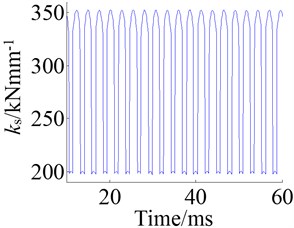
The Figure 7 shows the curves of anti-backlash gear composite mesh stiffness under the actions of single frequency excitation and frequency sweep excitation, and it is obvious that the frequency of mesh stiffness increases with the increment of excitation frequency.
Fig. 6Responses of the single frequency excitation
a)
b)
c)
d)
e)
f)
Fig. 7Mesh stiffness at 3 kHz and during frequency sweep: a) response at 3 kHz and b) response of frequency sweep
a)
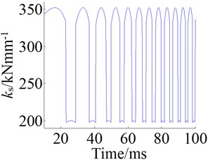
b)
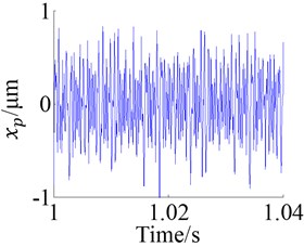
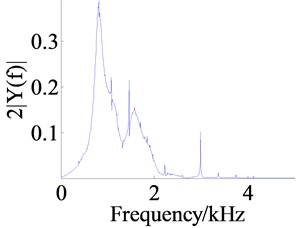
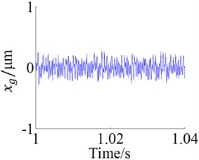
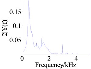
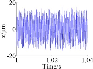
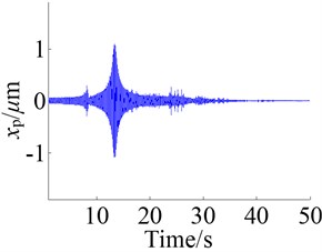
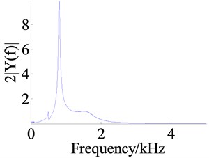
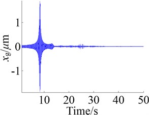
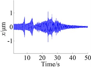
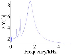
The Figure 8 shows the responses of the system under the action of frequency sweep excitation, where the Figures 8a, c and e are the figures of time domain response of the dynamic displacements , and and the Figures 8b, d and f are the figures of frequency response.
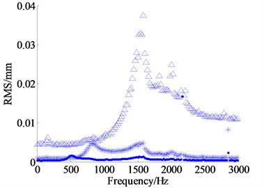
According to the time domain response, the amplitudes of dynamic displacements in the low frequency zone are generally large, which are small in the high frequency zone, and the amplitude of anti-backlash gear transmission error is the largest. From the Figure 9 the same result is obtained. The Figure 9 shows the RMSs (root mean square) of dynamic displacements in the action of different excitation frequencies, where the legends , , respectively represent the dynamic displacements , and . It is easy to see that the is the largest, followed by , is the smallest.
The main resonant peak of each dynamic displacement is shown in the figure of frequency domain response, and the resonant frequencies for , and are respectively about 810 Hz, 503 Hz and 1637 Hz. From the amplitude of main resonant peak, the amplitude of is the largest and the amplitude of is the smallest. The reason is that the RMS of is the largest and the frequency spectrum energy is more dispersed, so the amplitude of the resonant peak becomes small. Likewise, because the RMS of is the smallest, the frequency spectrum energy is more concentrated.
Fig. 8Responses of the frequency sweep
a)
b)
c)
d)
e)
f)
In addition to the main resonant peaks, some other resonant peaks can be found in Figures 8b, d and f. Comparing these peaks with each other, it is not difficult to find that the resonant frequency of corresponding peak is basically equal to each other, and just the amplitude has larger difference. It is maybe because that when some part of the system is in resonance, as an “external excitation” for the other parts, the relatively violent vibration causes the forced vibration of other part at this frequency. Of course, this is also worthy of further study.
Fig. 9The RMSs of dynamic displacements
4.3. The effect of some assembly parameters on the frequency characteristic of the system
4.3.1. The effect of shrink range
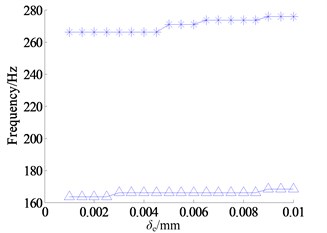
From the Figure 5, the effect of inner and outer ring shrink range on the bearing radial stiffness is almost the same, and both are not significant. So, in order to reduce the amount of calculation, the effect of the outer ring shrink range on the frequency response of the system is only considered in the paper. When calculating, set the shrink range of the inner ring equal to 0.005 mm, the radial and the axial preload force both equal to 1 kN, and other parameters refer to Table 1. When frequency sweep is starting, as the other parameters keep the same, the shrink range of outer ring increases linearly from 0.001 mm to 0.01 mm with the step size of 5e-4 mm, and the top 3 orders of resonant frequencies of each dynamic displacement in a certain shrink range of outer ring are obtained. Finally, the curves of the relationship between shrink range and resonant frequency of dynamic displacements are plotted in the Figure 10, where the legends -^-, -*- respectively represent the first and second order resonant frequencies.
Fig. 10Relationship between shrink range and RF: a) the 2 orders RF of dynamic transmission error x, b) the 2 orders RF of dynamic displacement xp and c) the first order RF of dynamic displacement xg
a)
b)
c)
According to the calculation result, the third order resonant frequency of each dynamic displacement does not change significantly, for the third order resonant frequency is about 1609 Hz, and the third order resonant frequency of and both are about 1526 Hz. Thus the third order resonant frequency is not shown in Figure 11. Moreover, the second order resonant frequency of is also not shown, because it is not obvious.
As shown in Figure 10(a), the dynamic transmission error increases slowly with the increment of shrink range, and the increment of the first order resonant frequency is about 5 Hz, the increment of the second resonant frequency is about 9.8 Hz, both of them are small, and even worse the shrink range is close to the limit. Likewise, in Figure 10b and Figure 10c the increments of the first and second order resonant frequencies of and are small too; the increments of the first order resonant frequencies both are about 5 Hz, and the increment of the second order resonant frequency of is about 8.6 Hz. In a word, it is useful to improve the resonant frequency of the system by increasing the shrink range of the bearing inner and outer ring, but the effect is small.
4.3.2. The effect of preload force
According to the Figure 5, the effect of axial preload force on the bearing radial stiffness is far less than that of radial preload force, thus the effect of axial preload force on the frequency characteristic is not considered.
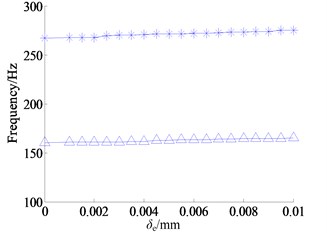
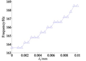
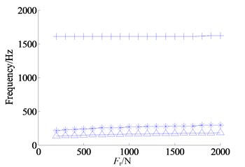
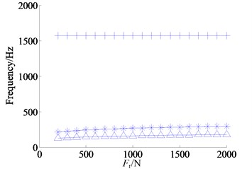
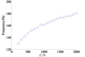
When frequency sweep is starting, set the shrink range of the inner and outer rings both equal to 0.005 mm, the axial preload forces both equal to 1.2 kN, and other parameters refer to Table 1. As the other parameters remain the same, the radial preload force increases linearly from 200 N to 2 kN with the step size of 100 N, and the top 3 orders of resonant frequencies of each dynamic displacement in the corresponding preload force are obtained. Finally the curves of the relationship between preload force and resonant frequency of dynamic displacement are plotted in the Figure 11, where the legends -^-, -*-, -+- respectively represent the first, the second and the third order resonant frequencies.
From the Figure 11(a), as the radial preload force increases from 200 N to 2 kN, the first and second order resonant frequencies of dynamic transmission error increase gradually, the first order resonant frequency increases from 131.8 Hz to 180.7 Hz, the increment is about 49 Hz, the second order resonant frequency increases from 210 Hz to 293 Hz, the increment is about 83 Hz, and the third order resonant frequency is basically unchanged, about 1620 Hz. Thus by the increasing of the bearing radial preload force, the low order resonant frequency of the system can be improved.
The first and second order resonant frequencies of dynamic displacement increase with the increment of radial preload force as shown in Figure 11(b), where the first order resonant frequency increases from 127 Hz to 178.2 Hz, the second order resonant frequency increases from 212.4 Hz to 295.4 Hz, and the third order resonant frequency is basically unchanged, about 1570 Hz.
Since the changes of the second and third order resonant frequencies of dynamic displacement are not obvious, only the curve of the first order resonant frequency is shown in Figure 11(c), and the first order resonant frequency and its variation range of are basically the same as the first order resonant frequencies of and .
Fig. 11Relationship between preload force and RF: a) the 3 orders RF of dynamic transmission error x, b) the 3 orders RF of dynamic displacement xp and c) the first order RF of dynamic displacement xg
a)
b)
c)
In summary, increasing the bearing preload force has benefit to improve the bearing contact stiffness, and also has positive effect on the improvement of the system resonance frequency. Although the effect of axial preload force on the improvement of the bearing contact stiffness and the system resonance frequency is less than of the radial preload, as shown in Figure 5, they both are positive.
5. Conclusions
(1) The analysis model of the contact bearing considering the assembly shrink range and the preload force was proposed, and the calculation formula of the bearing radial stiffness was given. The results of calculation and analysis show that the bearing radial stiffness can be improved by increasing the shrink range of the inner and outer ring, and by increasing the preload force of the bearing also can improve the bearing radial stiffness, however the effect of axial preload force on the improvement of the bearing contact stiffness is less than of the radial preload.
(2) A single anti-backlash gear transmission box was taken as an example, the calculation method of anti-backlash gear composite mesh stiffness was used, and the dynamics model with time-varying composite mesh stiffness and bearing stiffness of the anti-backlash geared rotor bearing system was proposed, and the dimensionless transverse-torsion dynamics differential equations of the system were derived. The proposed model, including some assembly parameters such as shrink range, preload force and anti-backlash spring stiffness, provides a basis for the further study on the dynamic characteristic and the control of assembly dynamic performance.
(3) The effect of bearing assembly shrink range and preload force on the system resonant frequency was analyzed. The analysis result shows that the resonant frequencies of the system can be obtained by frequency sweep, and as an excitation, the dynamics behavior of a part can have effect on the other parts; increasing the shrink range of the bearing inner and outer ring is useful to improve the resonant frequency of the system, but the effect is small; increasing the bearing preload force also has positive effect on the improvement of the resonance frequency, and the effect of axial preload force on the improvement of the resonance frequency is less than of the radial preload.
References
-
Charles W. Cairnes, et al. Anti-Backlash Gearing. US Patent: No. 2663198, ID: 22 Dec 1953.
-
Kwon Y. S. Rate loop control based on torque compensation in anti-backlash geared servo system. Proceedings of the American Control Conference, Boston, Massachusetts, 2004, p. 3327-3332.
-
Allan P. M., Levy N. M. The determination of minimum pre-load torque for anti-backlash gears in a positional servomechanism. IEEE Transactions on Industrial Electronics and Control Instrumentation, Vol. 27, 1980, p. 1232-1239.
-
Li Qing The double gear being applied in construction of radar. Modern Radar, Vol. 22, Issue 5, 2000, p. 83-86.
-
Harris T. A. Rolling Bearing Analysis. 3rd Edition, John Wiley and Sons, Inc., New York, 1990.
-
Qiu Ming, Jiang Xing-Qi, Du Ying-Hui, et al. Rigidity calculation for high speed angular contact ball bearings. Bearing, Issue 11, 2001, p. 5-8.
-
Okamoto Junzo Ball Bearing Design and Calculation. Machinery Industry Press, Beijing, 2003.
-
Wang Shuo-Gui, Xia Yuan-Ming Effect of the interference fit and axial preload in the stiffness of the high-speed angular contact ball bearing. Journal of University of Science and Technology of China, Vol. 36, Issue 12, 2006, p. 1314-1320.
-
Ei-Saeidy F. M. A. Time-varying total stiffness matrix of a rigid machine spindle-angular contact ball bearings assembly: theory and analytical/experimental verifications. Shock and Vibration, Vol. 18, Issue 5, 2011, p. 641-670.
-
Kahraman A., Singh R. Non-linear dynamics of a spur geared pair. Journal of Sound and Vibration, Vol. 142, Issue 1, 1990, p. 49-75.
-
Kahraman A., Singh R. Non-linear dynamics of a spur geared rotor-bearing system with multiple clearances. Journal of Sound and Vibration, Vol. 144, Issue 3, 1991, p. 469-506.
-
Bai C. Q., Zhang H. Y., Xu Q. Y. Effects of axial preload of ball bearing on the nonlinear dynamic characteristics of a rotor-bearing system. Nonlinear Dynamics, Vol. 53, Issue 3, 2008, p. 173-190.
-
Li Chao-Feng, Ren Zhao-Hui, Liu Jie, et al. Bifurcation and stability of the flexible rotor-bearing system by a continuum model. Chinese Journal of Applied Mechanics, Vol. 27, Issue 1, 2010, p. 173-178.
-
Chen Y. C., Kang C. H., Choi S. T. Vibration analysis of geared rotor system under time varying mesh stiffness effects. Journal of Vibroengineering, Vol. 14, Issue 3, 2012, p. 1141-1150.
-
Naoki I., Masayoshi T. Adaptive control of robot manipulators with anti-backlash gears. IEEE International Conference on Robotics and Automation, 1995, p. 306-311.
-
Yang Zheng, Shang Jianzhong, Luo Zirong, Wang Xiaoming, Yu Naihui Research on synthesis meshing stiffness of torsional spring-loaded double-gear anti-backlash mechanism. Journal of Mechanical Engineering, Vol. 49, Issue 1, 2013, p. 23-30.
-
Kuang J. H., Yang Y. T. An estimate of mesh stiffness and load sharing ratio of a spur gear pair. Proceedings of ASME 12th International Power Transmission and Gearing Conference, Scottsdale, Arizona, Vol. 43, Issue 1, 1992, p. 1-10.
-
Hamrock B. J., Dowson D. Ball Bearing Lubrication. John Wily and Sons, New York, 1981.
About this article

We thank the National Natural Science Foundation of China (Grant No. 51175505) for supporting.
