Abstract
For the looseness-rubbing coupling fault rotor-bearing system caused by pedestal looseness, the mechanical model and finite element model of dual-disk triad-supported looseness-rubbing coupling fault rotor-bearing system were established in this paper. The research of dynamics characteristics about the effect of rubbing stiffness and looseness stiffness on the system was done with equivalent stiffness model on the loose support, nonlinear finite element method, contact theory and the wavelet packet decomposition principle. It was demonstrated that alternating high and low peaks exist in the time domain while the trapezoidal shape appears in the orbit diagram of the signal. It was also found that the double frequency (2X) has a high energy distribution in the vibration signal. It could be used as fault frequency band of the looseness-rubbing coupling fault. These two characteristics (trapezoidal shape and double frequency) could serve as a basis in diagnosing looseness-rubbing coupling fault.
1. Introduction
Pedestal looseness fault of rotating machinery is usually caused by low installation quality and long-term vibration. The fault can generally be divided into rotating parts looseness and pedestal looseness, where the looseness between bearing seat and pedestal is more common. Rotor system with looseness fault can easily lead to collision and friction of the rotating parts and the statics, causing cyclical rubbing in operation and cyclical changes of the stiffness of the system, which will further lead the system to a looseness-rubbing coupling fault state. And if the situation worsens, it will cause unstable motion of the system or even shaft damage.
For years, relevant studies on the sophisticated dynamic phenomena in looseness and rubbing problems have been carried out by researchers both at home and abroad, and important results have also been achieved. Agnes Muszynska [1], by doing numerical simulation of the rotor system with pedestal looseness or rotor-stator rubbing fault and by carrying out experiment of rotor vibration characteristics, studied on the nonlinear dynamic action of the rotor system, and then provided a theoretical basis for the study on the pedestal looseness and rotor-stator rubbing fault. Yuegang Luo [2] established the local rubbing dynamic model of rotor system with pedestal looseness fault, conducted numerical simulation on the rotor system by numerical integration and the Poincaré mapping method and analyzed the impact of pedestal looseness quality on dynamic behaviors of the rotor system. Changli Liu [3], based on the nonlinear dynamic equations of the rotor bearing system with looseness-rubbing coupling fault, and by using the continuation shooting algorithm for solving the periodic solutions of nonlinear non-autonomous system, studied the stableness of the system’s periodic motion and its instability laws, and found the bifurcation set of the system within parameter domains such as unbalance-speed and rubbing gap-speed. Yanjun Lu [4] established the mechanical model and finite element model for the dual-disk vertical cantilever rotor-bearing system with looseness-rubbing coupling fault, and based on the nonlinear finite element method and the contact theory, studied the impact of two important coefficients (looseness stiffness and rubbing gap) on the system’s dynamic characteristics. A model of triad-supported dual-disk rotor-bearing system with looseness-rubbing coupling fault was established in this paper. By using the Newmark-β method for solving the numerical solution of nonlinear non-autonomous system, this paper analyzed the dynamic characteristics of the periodic motion of the middle bearing looseness-rubbing rotor system when it is in different rubbing and looseness stiffness coefficient domains and obtained the main characteristics of the looseness-rubbing coupling fault of the rotor system, which serves as a theoretical reference for fault diagnosis of the rotor-bearing system.
2. Mathematical model of looseness-rubbing coupling fault rotor
2.1. Mechanical model of rotor system
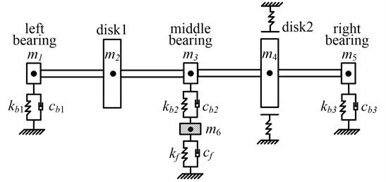
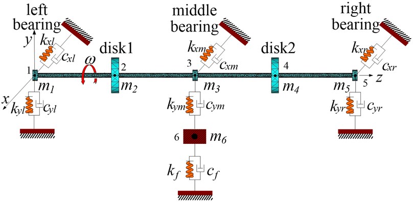
The object of this paper is a simplified dual-disk triad-supported rotor-bearing system, which consists of 2 disks and 3 elastic supporting bearings. And the middle bearing incurs pedestal looseness, as shown in Figure 1. The span of the 3 bearings between every two is ; the distances between disk 1 and the left bearing and that between disk 2 and the right bearing are both ; the distance between the middle bearing and disk 1, 2 is ; are equivalent supporting stiffness and damping respectively for the left, middle and right three bearings; are equivalent supporting stiffness and damping respectively between the bearing block and pedestal; from left to right is the mass of bearing and disk; is the equivalent mass of the middle bearing; there is a casing with disk 2.
Fig. 1Mechanical model of rotor bearing system
2.2. Equivalent stiffness model of the looseness part
Suppose that the tensile stiffnesses of the loose bolt and unloose bolt are , , that of the pedestal is , as shown in Figure 2.
Fig. 2The schematic diagram of pedestal looseness
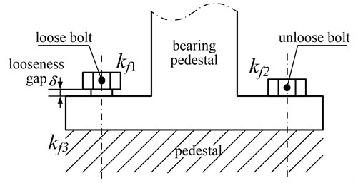
When the vibration amplitude is large, the bearing supports and pedestal separates temporarily, the unloose bolt is in a state of elastic deformation, the equivalent stiffness of the loose part is ; as the vibration amplitude further increases and the displacement of bearing support exceeds , loose bolts with other bolts will generate tension to the bearing support, the equivalent stiffness is ; when the vibration amplitude is small and after the bearing block contacts with the pedestal, the pedestal generates deformation and shift, the equivalent stiffness is that of the pedestal . Take the looseness in the direction for example, the equivalent stiffness of the middle bearing with looseness fault [5-7] is:
Suppose that the pedestal stiffness is approximately equal with tension stiffness, which is , so the Eq. (1) can be simplified as:
2.3. Rubbing model based on Hertz contact theory
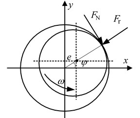
According to the Hertz contact theory, it can be considered that with two surfaces in contact and compression the pressure acts along the -axis. Near the initial contact point, local material deformation forms a small oval-shaped flat whose oval long axis is in the -axis and minor axis in the -axis. In the oval-shaped contact surface the unit pressure in each point has relation to the material deformation amount. The greatest unit pressure generates along the -axis because the largest deformation emerges in this direction. The distributions of unit pressure in other points are based on the oval ball law, and then the following assumptions can be made to simplify the research [8-10]: 1. With the rotor and stator in contact, the contact pressure is perpendicular to their common tangent plane; 2. When the rubbing occurs between the rotor and stator, with the damping effect in the compression process ignored, the local elastic deformation exists only in the contact area; 3. The tangential friction force is in line with the Coulomb law, namely , as shown in Figure 3.
Fig. 3Rubbing force model between rotor and stator
According to the Hertz contact law the normal force caused by the collision of two elastomer’s is:
in which is radial embedding depth; is structure constant, whose expression is:
, , are Poisson’s ratio, Young’s modulus and curvature radius of the rubbing surface respectively. In practical engineering the radius gap between rotor and stator is only one over one thousand of the in general, so is:
In the rubbing process of rotor and stator, whose radial rubbing stiffness can be expressed as the following nonlinear form brief:
in which , is the rotor’s radial displacement, , is step function, whose expression is:
Fig. 4The trend of rubbing stiffness with embedded depth under different models
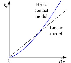
According to the Eq. (6) the relationship curve between rubbing stiffness and the embedded depth of the rotor and stator in the Hertz contact model is shown in Figure 4. The parameter depends on the rotor radial displacement , when the radius gap between rotor and stator is a constant. And it is also found that the relationship in the linear contact model is linear [11].
The components which are the rubbing force between rotor and stator in the , coordinates are:
Through the Eq. (5) and Eq. (6) it was known that the essential characteristic of elastomer radial collision was mainly decided by structure constants . Structure constant is a geometry parameter related with curvature radius of collision point and material properties , . For example, the material of rotor is cast iron, its Young’s modulus 2.07×10¹¹ Pa, Poisson’s ratio 0.3; the material of stator is copper, its Young’s modulus 2.15×10¹¹ Pa, Poisson’s ratio 0.3. So the rubbing stiffness can be got.
2.4. Mathematical model of rotor system
Figure 5 shows the finite element model of the rotor system shown in Figure 1 which is made discrete. The dots in the figure denote nodes with their numbers. The left, middle, right three bearings are born on the node 1, 3 and 5, the three supporting bearings are simplified as springs-dampers. The masses of the disks are born on the nodes 2 and 4, the looseness fault of the support is simulated by the node 6 with a piecewise linear spring-damper element. The rubbing force uses Hertz model. The whole rotor system’s motion equation can be described as:
in which includes the mass matrix of the axis and the disk; is the damping matrix of rotor bearing and gyroscopic moment; is the whole stiffness matrix; , are the unbalanced force and rubbing force; is the displacement vector, .
Fig. 5Element model of rotor bearing system
As shown in Figure 5, due to the horizontal displacement of loose bearing it is very small compared to the vertical direction, so the analysis only considers vertical displacements. Eq. (10) and Eq. (11) respectively are the system movement differential equations in the horizontal direction and vertical direction:
in which from left to right are the masses of bearings and disks; is the equivalent mass of the middle bearing; is rotational speed; are moments of inertia of the radial; are polar moments of inertia; , , , , , , , , , , , are equivalent supporting stiffnesses and dampings respectively for the left, middle and right three bearings; , are equivalent supporting stiffness and damping respectively between the bearing block and pedestal, its equivalent looseness stiffness is shown in Eq. (2). , respectively are the displacements of node in the horizontal direction and vertical direction. , respectively are the rotation angles of node around the axis and axis. can be got in the literature [12]. , is the unbalanced force in the direction and direction respectively. And , is the rubbing force in the direction and direction respectively. It is shown in Eq. (8).
3. Non-linear dynamic analysis of coupling fault rotor system
In order to study the dynamic behavior of the dual-disk triad-supported rotor system fully, we need to study the nonlinear dynamic response of the system. Because the system’s non-linear characteristic is significant, this paper chooses the Newmark-β method [13-16], which does not require high precision for the integral step, to do the numerical integration and acquire rotor response, mainly studying the influence of rubbing stiffness and looseness stiffness to system’s dynamic characteristics.
The main parameters are as follows: shaft diameter is 10 mm, shaft length is 640 mm, disk diameter 80 mm, disk thickness 15 mm, bearing stiffness 2e5 N/m, damping 2e3 N/m, rotation velocity 4500 r/min that is between first-order and second-order critical rotation velocities, friction coefficient 0.3, rubbing clearance 210 μm, foundation stiffness 1×10⁹ N/m, bearing pedestal mass 1.1 kg, looseness gap 10 μm.
3.1. Influence of rubbing stiffness
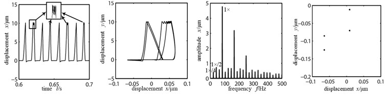
Suppose that the eccentric mass is only applied on the two disks, the unbalance quantity is 156e-6 kg.m, the bolt tension stiffness (looseness stiffness) is 8×10⁵ N/m. Rubbing fault occurs in the right side disk 2. In order to better observe the influence of the rubbing stiffness changes to the system, the (a)~(c) in Fig. 6 are the time-domain graph, orbit diagram, frequency spectrogram and Poincare graph on rubbing disk (node 4) with the rubbing stiffness being 2×10⁵ N/m, 5×10⁶ N/m and 8×10⁷ N/m.
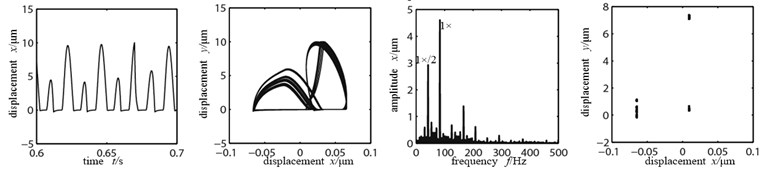
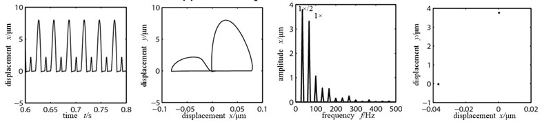
As shown in Figure 6(a), the rubbing stiffness is 2×10⁵ N/m, the impact of the looseness part vibration on disk is small, the rubbing between disk and stator is light, movement of the disk did not show significant direction, time-domain waveform and the axis of the track did not show significant changes, the rubbing stiffness is relatively low and the system mainly does working frequency motion, but there has been some high frequency multiplication composition, the double frequency is most obvious, which shows that it produces a stiffness mutation because of collision when the looseness bearing blocks contact with the pedestal. There is a single dot that appears in Poincare graph, which shows that the system is doing cycle 1 motion. Figure 6(b) is the time-domain graph, orbit diagram, frequency spectrogram and Poincare graph with the rubbing stiffness being 5×10⁶ N/m. At this time the increased rubbing stiffness makes the axis orbit evolve to two nested oval curves, the high and low peaks appear alternately in time-domain waveform, frequency components are more abundant and the high frequency peak increases significantly with a 1×/2 frequency division, the Poincare graph shows two single dots, all of which indicate the system’s frequency division motion characteristics, changing from cycle 1 to cycle 2 motion. When the rubbing stiffness shifts to 8×10⁷ N/m, the time-domain waveform and axis orbit are in confusion. Seeing from the Poincare graph and frequency spectrogram, there appear many dispersed dots. The axis orbit becomes complicated “8” shaped and the frequency spectrogram appears with continuous spectra, which can be observed by enlargement, all indicating that the system is doing chaotic motion.
Fig. 6Time-domain graphs, orbit diagrams, frequency spectrograms and Poincare graphs of rotor system with the change of rubbing stiffness
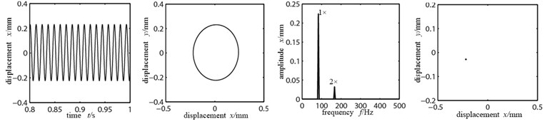
a) Rubbing stiffness 2×10⁵ N/m
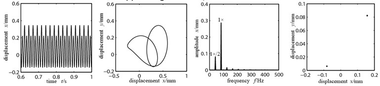
b) Rubbing stiffness 5×10⁶ N/m
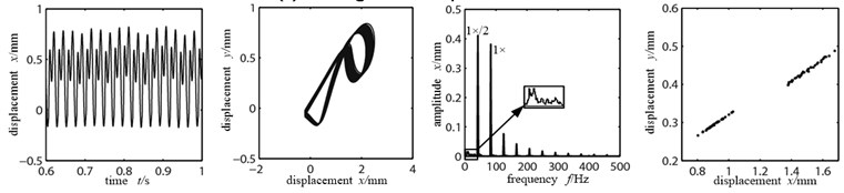
c) Rubbing stiffness 8×10⁷ N/m
3.2. Influence of the looseness stiffness
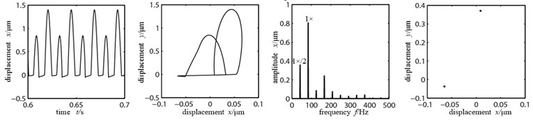
Because of rubbing force, the influence of the looseness stiffness change on rubbing disk (node 4) is not very obvious, that on the system’s dynamic response directly reflects in the loose node (node 6). In order to observe easily, Figure 7(a)~(c) are the time-domain graphs, orbit diagrams, frequency spectrograms and Poincare graphs of rotor system at the looseness node (node 6) with the looseness stiffness 1×10⁵ N/m, 5×10⁵ N/m and 5×10⁶ N/m when rotation speed is 4500 r/min, rubbing stiffness 5×10⁶ N/m.
As shown in the time-domain waveform in Figure 7(a), when the looseness stiffness is small, the nodal displacement peak is high. Bearing pedestal hits the loose bolt and appears “cutting peak microseism”, two ends of the axis orbit are suppressed and appears trapezoidal shape similarly, when displacement peak is larger than the looseness gap 10 μm, which is in accordance with the result of literature [17-18], there are 1×/4 harmonic waves appearing in frequency spectrogram, double frequency peak is relatively large, which shows that the system is doing cycle 4 motion. When the looseness stiffness shifts to 5×10⁵ N/m, there is a phenomenon that the high and low peaks appear alternately in the time-domain waveform Figure 7(b), it shows the segmentation features of support stiffness with the typical fault characteristic of pedestal looseness, the axis orbit is in confusion, there appear multiple nested semi-elliptical orbits, the frequency spectrogram appears with continuous spectra, but in the Poincare graph there appear many dispersed dots, the system changes to cycle motion. When the looseness stiffness further increases to 5×10⁶ N/m, the nodal displacement peak decreases sharply, the high and low peaks maintain appearing alternately, period of motion is not changing obviously, axis orbit appears as two nested semi-elliptical orbits, the vibration response frequency spectrogram appears as abundant discrete spectrum, the energies of working frequency and 1×/2 frequency division are large, working frequency is remaining as dominant frequency. There are two single dots in Poincare graph, which shows that the system is doing cycle 2 motions.
Fig. 7Time-domain graphs, orbit diagrams, frequency spectrograms and Poincare graphs of rotor system with the change of looseness stiffness
a) Looseness stiffness 1×10⁵ N/m
b) Looseness stiffness 5×10⁵ N/m
c) Looseness stiffness 5×10⁶ N/m
3.3. Influence of the rotational speed
Rotational speed has a direct influence on the dynamic behavior of the rotor system. In order to observe the system’s dynamic response easily, we choose the loose node (node 6) as the observation point. Figure 8(a)~(c) are the time-domain graphs, orbit diagrams, frequency spectrograms and Poincare graphs at the loose node (node 6) with rotational speeds being 3500 r/min, 4000 r/min, 6000 r/min, when the looseness stiffness 8×10⁵ N/m and the rubbing stiffness 5×10⁶ N/m.
Fig. 8Time-domain graphs, orbit diagrams, frequency spectrograms and Poincare graphs of rotor system with the change of rotational speed
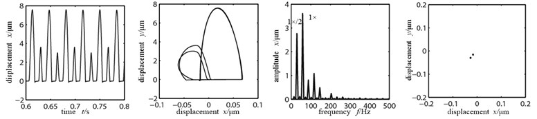
a) Rotational speed 3500 r/min
b) Rotational speed 4000 r/min
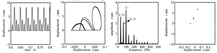
c) Rotational speed 6000 r/min
As shown in Figure 8(a) when the rotational speed is 3500 r/min, at this time, the rubbing fault between rotor and stator just has occurred. And with the existence of looseness fault the high and low peaks appear alternately in the time-domain waveform. There appear two nested semi-elliptical trajectories in the axis orbit. The vibration response frequency spectrogram appears abundant as of discrete spectrum. The energies of working frequency and 1×/2 frequency division are large. But the working frequency is remaining as dominant frequency. And through observing the Poincare graph we can see that the system is doing cycle 2 motions. With the further increase of rotational speed, the rubbing between rotor and stator further enhances. The phenomenon that the high and low peaks appear alternately in the time-domain waveform in Figure 8(b) is more apparent. There is a little change in the axis orbit diagram. At the same time there are still two single dots in the Poincare graph. And the system’s movement is in cycle 2. When rotational speed goes up to 6000 r/min, which is far surpassing the first-order critical speed of the system, the rubbing fault of rotor and stator is serious. And both the time-domain waveform and orbit graph become chaotic and distortion degree is becoming larger. Continuous spectrum appears in the frequency spectrogram. The 1×/3 frequency division has occurred. Three points appear in the Poincare graph and the system goes into cycle 3 motion. If the rotational speed continues to increase, the system will go into chaos through cycle 3 motion.
3.4. The fault characteristic frequency band
As shown in Figure 8(a)~(c), basic axis orbit, time-domain waveform and frequency spectrogram can judge the fault degree of rotor system roughly. But the fault characteristic cannot be judged in detail quantitatively.
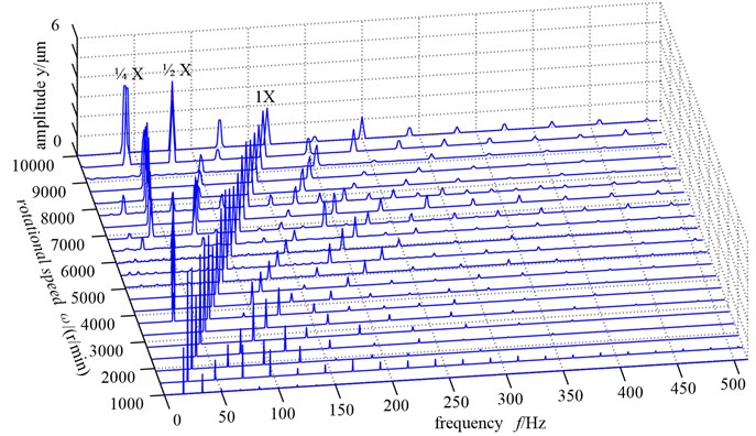
In order to obtain looseness-rubbing coupling fault characteristic further, auxiliary experiments were performed. The experiment is the continuation of the simulation. The dual-disk rotor bearing system was constructed for auxiliary experiments with the Bently RK-4 rotor test bench. Test bench is shown in Figure 9. All the parameters of test bench are same as the material parameters in the simulation calculation. So it can be seen that the experimental result verified the correctness of the simulation calculation results in the section 3.3 as shown in Figure 10. And then the experimental data within four different rotational speeds (1000 r/min, 2000 r/min, 3000 r/min, 4000 r/min) can be got. Based on the wavelet packet decomposition principle, the characteristics of looseness-rubbing coupling fault can be confirmed in detail with the experimental data.
Fig. 9The general view of the experimental rotor system
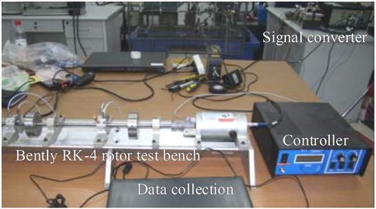
Fig. 10The amplitude-frequency three-dimensional waterfall figure changing with the rotational speed
For a comprehensive study of the looseness-rubbing coupling fault characteristic of the rotor system, based on the wavelet packet decomposition principle, fault data within four different rotational speeds (1000 r/min, 2000 r/min, 3000 r/min, 4000 r/min) adopt “db44” wavelet function to carry out four layers wavelet decomposition [19-22]. Thus 16 independent and equal bandwidth bands are obtained. For the purpose of collecting the fault frequency band effectively, re-sampling of vibration data is performed and the sampling frequency is 1024 Hz, namely the analysis frequency is 1024 Hz, so bandwidth of every band frequency is 32 Hz.
Through further application of the energy proportion computation method of the wavelet packet decomposition, vibration data wavelet packet decomposition of each frequency band energy ratio are obtained, which are shown in Figure 11. And the detailed ratio value of the frequency band energy is shown in Table 1. In Figure 11 we can see the vibration characteristics of the vibration signal in each frequency band and the distribution of energy ratio within different rotational speeds clearly. Apart from the basic frequency (1X), all the vibration data in double frequency (2X) have the high energy distribution. So the double frequency (2X) is the characteristic frequency band of looseness-rubbing coupling fault. The band 2, band 3, band 4, band 5 are the characteristic frequency bands of looseness-rubbing coupling fault in four different rotational speeds (1000 r/min, 2000 r/min, 3000 r/min, 4000 r/min) respectively. Through the comparison of the detailed frequency band energy ratio values of fault features, it can be accurately described and distinguished the severity of the system fault. When the rotational speed is a little lower as well as there is the existence of looseness fault, fault frequency band has a certain amount of ratio value (0.0271). With the increase of rotational speed, it will cause the rubbing fault of rotor system. At the same time, the fault frequency band ratio value rises increasingly. When the rotational speed reaches 4000 r/min, the ratio value of fault frequency band goes up to 0.1142, which shows that the system has reached a very serious fault degree. In a word, the increase of the rotational speed causes the system fault degree to become more serious.
Fig. 11Signal band energy proportion figure with different rotational speeds
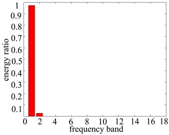
a) 1000 r/min
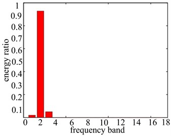
b) 2000 r/min
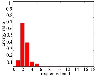
c) 3000 r/min
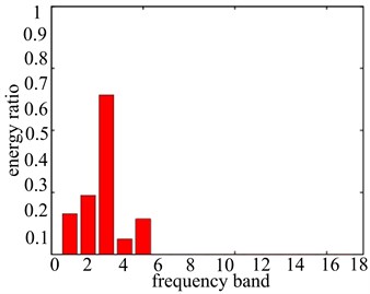
d) 4000 r/min
Table 1Each band energy proportion numerical values with different rotational speeds
1000 r/min | 2000 r/min | 3000 r/min | 4000 r/min | |
1 | 0.9729 | 0.0206 | 0.0738 | 0.1309 |
2 | 0.0271 | 0.9284 | 0.5349 | 0.1905 |
3 | 2.183e-9 | 0.0506 | 0.2945 | 0.5141 |
4 | 3.43e-10 | 3.149e-5 | 0.0607 | 0.0497 |
5 | 1.138e-11 | 1.778e-5 | 0.0354 | 0.1142 |
6 | 3.789e-12 | 2.929e-4 | 1.722e-4 | 1.023e-5 |
7 | 1.319e-12 | 8.917e-7 | 2.686e-5 | 4.45e-4 |
8 | 5.044e-12 | 6.815e-6 | 1.577e-4 | 9.981e-6 |
9 | 5.418e-12 | 3.761e-6 | 8.185e-5 | 2.909e-5 |
10 | 1.135e-13 | 9.149e-6 | 2.538e-4 | 1.873e-6 |
11 | 3.976e-14 | 5.44e-9 | 1.351e-5 | 6.973e-5 |
12 | 4.363e-15 | 5.732e-7 | 1.74e-5 | 3.169e-6 |
13 | 5.758e-15 | 1.091e-7 | 4.902e-6 | 4.67e-5 |
14 | 2.961e-14 | 8.028e-8 | 2.849e-7 | 1.036e-6 |
15 | 1.091e-14 | 4.918e-8 | 1.555e-6 | 1.481e-6 |
16 | 1.807e-15 | 1.151e-7 | 9.944e-6 | 5.699e-7 |
4. Conclusions
(1) The looseness-rubbing coupling fault of rotor-bearing system was studied in this paper. The rubbing between the rotor and stator can reduce the lower frequency vibration which is caused by looseness. However it was demonstrated that the frequency component was very much due to the effect of rubbing force in the frequency spectrogram of the signal.
(2) It could be found that the following characteristic could serve as a basis in diagnosing looseness-rubbing fault: the high and low peak appears alternately in time-domain waveform while the trapezoidal shape appears in the orbit diagram.
(3) Based on the wavelet packet decomposition principle, each frequency band energy ratio of vibration signal can be obtained. We can see that the double frequency (2X) has a high energy distribution in the vibration signal. It could be used as fault frequency band of the looseness-rubbing coupling fault. It also could serve as a basis in diagnosing looseness-rubbing coupling fault.
References
-
Agnes Muszynska, Paul Goldman. Chaotic responses of unbalanced rotor/bearing/stator systems with looseness or rubs. Chaos, Solitons & Fractals, Vol. 5, Issue 9, 1995, p. 1683-1704.
-
Yuegang Luo, Haiquan Zeng, Zhenping Li, et al. Study on chaos behaviors of rotor systems with local rubbing and pedestal looseness faults. Journal of Vibration Engineering, Vol. 16, Issue 2, 2003, p. 184-188, (in Chinese).
-
Changli Liu, Hongliang Yao, Yuegang Luo, et al. Dynamics of rotor-bearing system with coupling faults of pedestal looseness and rub-impact. Journal of Vibration Engineering, Vol. 17, Issue 3, 2004, p. 336-340, (in Chinese).
-
Yanjun Lu, Zhaohui Ren, Hong Chen, et al. Study on looseness and impact-rub coupling faults of vertical dual-disk over-hung rotor-bearing system. Journal of Vibration, Measurement & Diagnosis, Vol. 27, Issue 2, 2007, p. 102-107, (in Chinese).
-
Hongliang Yao, Changli Liu, Xiaowei Zhang, et al. Dynamics of pedestal looseness rotor system near the critical speed region. Journal of Northeastern University (Natural Science), Vol. 24, Issue 8, 2003, p. 798-801, (in Chinese).
-
Bangchun Wen, Xinhua Wu, Qian Ding, et al. The Nonlinear Dynamics Theory and Experiment of Fault Rotating Machinery. Beijing, Science Press, China, 2004, (in Chinese).
-
Chu F., Tang Y. Stability and non-linear responses of a rotor-bearing system with pedestal looseness. Journal of Sound and Vibration, Vol. 241, Issue 5, 2001, p. 879-893.
-
Turner B. L., Kasperson R. E., Matson P. A., et al. A framework for vulnerability analysis in sustainability science. PNAS, Vol. 100, No. 14, 2003, p. 8074-8079.
-
Changli Liu, Pengru Xie, Shaoping Zhou, et al. Dynamics characteristics of rotor with breathing crack using finite element method. Journal of Vibration, Measurement & Diagnosis, Vol. 31, Issue 2, 2011, p. 185-189, (in Chinese).
-
Seo Hojin, Kim Eunjin, Kim Huykang. A novel biometric identification based on a user’s input pattern analysis for intelligent mobile devices. International Journal of Advanced Robotic Systems, Vol. 9, Issue 46, 2012, p. 400-410.
-
Yang Liu, Qinliang Li, Yazhe Chen, et al. Dynamic analysis of rubbing rotor system based on Hertz contact theory. Advanced Materials Research, Vol. 2012, Issue 479-481, 2012, p. 743-747.
-
Yie Zhong, et al. Rotor Dynamics. Beijing, Tsinghua University Press, China, 1987, (in Chinese).
-
Bradford M. A., Yazdi N. Abdoli. Newmark-based method for the stability of columns. Computers & Structures, Vol. 71, Issue 6, 1999, p. 689-700.
-
Lee A. C., Kang Y., Liu S. L. Steady analysis of a rotor mounted on nonlinear bearings by the transfer matrix method. International Journal of Mechanical Sciences, Vol. 35, Issue 6, 1993, p. 479-490.
-
Chen Guo Nonlinear dynamic study on a rotor-ball bearing system with unbalance-rubbing coupling fault. Journal of Vibration and Shock, Vol. 27, Issue 4, 2008, p. 43-48, (in Chinese).
-
Chen C. L., Yua H. T. Chaos in the imbalance response of a flexible rotor supported by oil film bearing with nonlinear suspension. Nonlinear Dynamics, Vol. 16, Issue 1, 1998, p. 71-90.
-
Hui Ma, Wei Sun, Xuejun Wang, et al. Characteristic analysis of looseness fault in rotor system. Journal of Northeastern University (Natural Science), Vol. 30, Issue 3, 2009, p. 400-404, (in Chinese).
-
Hui Ma, Xueyan Zhao, Yunnan Teng, et al. Analysis of dynamic characteristics for a rotor system with pedestal looseness. Shock and Vibration, Vol. 18, Issue 1, 2001, p. 13-27.
-
S. B. Chun, C. W. Lee Vibration analysis of shaft-bladed disc system by using substructure synthesis and assumed modes method. Journal of Sound and Vibration, Vol. 189, Issue 5, 1996, p. 587-608.
-
G. Genta, A. Tonoli. A harmonic finite element for the analysis of flexural, torsional and axial rotordynamic behavior of blade arrays. Journal of Sound and Vibration, Vol. 107, Issue 5, 1997, p. 693-720.
-
N. Lesaffre, J. J. Sinou, F. Thouverez. Contact analysis of a flexible bladed-rotor. European Journal of Mechanics A/Solids, Vol. 26, Issue 3, 2007, p. 541-557.
-
J. H. Jia, X. Y. Shen, H. X. Hua. Viscoelastic behavior analysis and application of the fractional derivative Maxwell model. J. Vib. Control, Vol. 13, Issue 4, 2007, p. 385-401.
About this article

This work was financially supported by the National Natural Science Foundation of China for Young Scientists (Grant No. 51105065), Exploration-Oriented Key Scientific and Technological Innovation Project from Ministry of Education of China (Grant No. N110203001).
