Abstract
Dynamic analysis of a beam on a moving vehicle is presented in this paper. The vehicle is simulated by a four degrees-of-freedom mass-spring system and the beam on top is supported by spring-damping systems. Two contact models named the ‘point contact’ and the ‘patch contact’ respectively, are adopted to simulate the interaction between road surface and vehicular tyres. The equation of motion of the beam-vehicle system is formulated and the dynamic response on the beam under the excitation of the irregular road surface is derived. Numerical simulations are conducted to demonstrate the influence of different factors, such as the length of the contact, the velocity of vehicle, the road condition and the bracing stiffness, etc. on the vibration level of the beam structure, which aims to provide references on the vibration problem in transporting a beam-shaped package.
1. Introduction
Vibration problems generally existed during road transportation especially when packages are flexible with large slenderness ratio, such as missiles, prefabricated concrete beams, etc. These packages can be regarded as beam-shaped structures which may suffer from long distance transportation before service and damages may initiate due to the vibration caused by the unevenness of the road profile. There are mainly two kinds of road excitations: (1) the stochastic excitation due to the road surface roughness; (2) the impact excitation due to an irregularity causing bouncing of vehicle. The impact excitation will result in a sudden increase in the dynamic response, which may cause damages in structure as well as the equipment inside; the amplitude of the vibration on packages under stochastic excitation is relatively small compared with that from the impact, but it may cause fatigue damage in the packages during long distance transportation. Therefore, to study the dynamic response of the beam-shaped packages under the road excitation is very important for the condition assessment and vibration control during transportation.
Research work on the vibration analysis of vehicle as well as the packages on top due to the excitation from irregular road profile has been conducted for decades. Shi and Cai [1] investigated the dynamic effects of vehicle by a three-dimensional vehicle-pavement coupled model and concluded that the dynamic vehicular axle loads are significantly higher than the static ones under rough road condition. Michaltsos [2] proposed a mathematical model to determine the critical velocity when the vehicle loses touch with the road surface during the bouncing due to an irregularity. Lu et al. [3] investigated the acceleration on vehicle under both the stochastic and impact excitations at different traveling speeds with experimental and analyzing approaches, results indicate that the effect of truck speed on root mean square acceleration including shock and vibration was strong at lower speed, but slight at a higher speed. Lak et al. [4] studied the relationship among the road unevenness, the dynamic vehicle response and ground-borne vibration with in situ measurements of road unevenness and a 3D two-axle vehicle model, results show that the predicted RMS value of dynamic response on vehicle is generally larger than the measurement data. Similarly, based on the measurement of road surface roughness and a half-car model, Barbosa [5] studied the vibration response of vehicle using a spectral method in frequency domain.
All the aforementioned research works focus on the vibration of vehicle body due to road excitation. During the road transportation of packages, more attention should be paid on the vibration level of the package and the design of its bracing system. Ghaith [6] proposed a nonlinear dynamic model to analyze the dynamic response of a Bernoulli-Euler beam fixed on a moving cart carrying lumped tip mass subjected to external periodic force, which aims to describe the motion of structures like forklift vehicles or ladder cars that carry heavy loads and military airplane wings. Ragulskis et al. [7] studied the dynamic response of a container with package during transportation and suggested that to avoid the overload, the velocity of vehicle must ensure the maximum difference between the excitation frequency and the nature, frequency of the system.
In most of the research works on vibration analysis of package during road transportation, the contact between vehicular tyres and road surface is assumed as a point in the dynamic model. In reality, pneumatic tyres will deform due to static/dynamic loads from the vehicle body which results in a footprint area called patch contact between tyres and road surface. Studies on modeling of pneumatic tyres [8] and the relationship among the loads, deformation of tyres and the inflation pressure have been conducted [9]. Yin et al. [10] introduced the patch contact model of pneumatic tyres in bridge-vehicle interaction problem, results show that treating the interaction between tyres and road surface as point contacts may over-estimate the dynamic deflection of the bridge. With patch contact models adopted, the accuracy of the dynamic response of the bridge under moving vehicular loads can significantly be improved compared with that analyzed with point contact simulations.
Since the patch contact model shows great advantage over the point contact model in bridge-vehicle interaction problem, a study is conducted in this paper by introducing the patch contact model in the vibration analysis of a beam-shaped package on a moving vehicle under road excitation. The package and vehicle are modeled by a Bernoulli-Euler beam and a four Degrees-Of-Freedom (DOFs) mass-spring system respectively, the bracing systems between the package and vehicle are simulated by spring-damping systems. The road surface roughness is assumed to have a Power Spectral Density (PSD) defined according to the ISO standard [11]. A comparison of the dynamic response on the beam with the two different contact models adopted will be given and different factors which may affect the vibration level of the beam will also be discussed.
2. The beam-vehicle model
The schematic diagram of the beam-vehicle model with the point contact model for tyres is shown in Fig. 1a, where and are the two interaction forces at the braces between the vehicle body and the beam respectively. and are the two interaction forces between tyres and road surface. Parameters and are the stiffness and the damping of the braces between the vehicle and beam respectively. is the distance from the left end of the beam to the th bracing system. and represent the distance between the bracing system and the center of the vehicle body respectively.
Fig. 1The beam-vehicle model
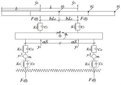
a) The schematic diagram
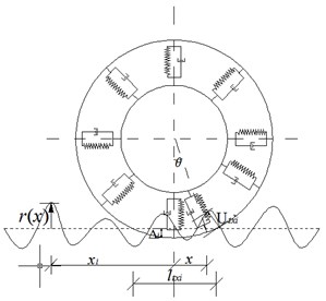
b) The patch contact model
Similarly and are the distances between the wheels and the center of the vehicle body respectively. The symbols , , and represent the mass, stiffness, damping and displacment of the th suspension system respectively. Variables and are the deflection at the bracing systems on the beam and the vehicle body respectively. and are the vertical displacement and pitch displacement of the vehicle body respectively. Location #1, #2 and #3 are the right end, 1/4 point and mid-point of the beam respectively. , are the stiffness and damping of the th tyre modeled by point contact model. The patch contact model for tyre is shown in Fig. 1b and further explainations will be given in Section 2.2.
2.1. Finite element model of the beam-shaped package
The beam-shaped package is modeled by a Bernoulli-Euler beam. The equation of motion is given as:
where , and are the mass per unit length, damping and the flexural rigidity respectively. is the deflection on the beam at location and time . The term in the right side of Eq. (1) represents the excitation forces from the bracing systems. is the number of the braces equal to 2 in this study. Though only two bracing systems are involved in the beam-vehicle system, more forces can be included in Eq. (1) without additional changes of the expression. By adopting the finite element discretization, the finite element model can be obtained as:
where , and are the mass, damping and stiffness matrices of the beam model respectively; , and are the vectors of nodal displacements, velocities and accelerations respectively; is the location matrix for the dynamic interaction forces at the braces which has the following expression:
where is the number of DOFs of the beam with boundary conditions. represents the shape functions of the beam element on which the th force is applied, and:
where is local coordinate on the beam element for the th brace. is the vector of static components of the interaction force at the braces due to the weight of the beam and:
where is the length of the beam and is the acceleration of gravity.
2.2. Equation of motion of vehicle
The vehicle is modeled by a four DOFs mass-spring system. The equation of motion of the vehicle is derived using the Lagrange formulation as follows:
where , and are the vectors of displacement, velocity and acceleration on the vehicle model respectively, and . Other sub-matrices and vectors in Eq. (6) have been listed in Appendix 1. It is noted that the modeling of vehicle with point contact model or patch contact model respectively, share the same form of equation of motion in Eq. (6). However sub-matrices related to the tyres and the interaction forces between pneumatic tyres and road surface included in the force vector will be different.
When the point contact model is adopted, the dynamic interaction forces between the pneumatic tyres and the road surface are:
where are the stiffness and damping for the point contact model of the two tyres respectively; , are the road surface roughness at the two contact points respectively. The over-dot (∙) denotes the differentiation with respect to time and the right prime (′) denotes the differentiation with respect to space coordinate in this paper. Since the modeling of point contact in the vehicle model may result in an over-estimation of the dynamic response on the beam-shaped package [10], the patch contact model will also be introduced.
In Fig. 1b the patch contact model [10] is presented, where denote the location of the th tyre on the road, and are the length of patch contact and the deformation at the center of the th tyre respectively. is the deformation at location on the th tyre:
where is the radius of tyre, and:
The central deformation and the corresponding length of patch contact when the beam-vehicle system is at rest can be obtained according to the practical inflation pressure of the th tyre. The implementation procedure [12] is as follows:
(1) To determine the average deformation of all the tyres denoted as with standard inflation pressure under the total weight of the beam-vehicle system :
where and denote the total number of the tyres on vehicle and the width of the tyres respectively. The standard inflation pressure is generally equal to .
(2) To estimate the practical inflation pressure according to the average deformation of tyre (in the case of a two-axle vehicle):
where are the static vehicular axle loads, , are two constants for heavy vehicles.
(3) To calculate the parameter factor and stiffness factor from the practical inflation pressure :
(4) Finally the central deformation and the corresponding length of patch contact of the th tyre on the road surface can be obtained according to Eqs. (14) and (15) repectively:
where is the ratio between the real contact area and the assumed rectangular contact area, which generally equals to .
The axial deformation at location on the th tyre denoted as can be calculated as:
When the stiffnesses of the patch contact model for the two tyres are represented by , the relationship between the two static vehicular axle loads and the deformation of tyres can be expressed as:
Therefore when the patch contact model is adopted, the dynamic interaction forces between the pneumatic tyres and the road surface can be obtained as:
2.3. Equation of motion of the beam-vehicle system
With the finite element model of the beam-shaped package and the equation of motion of the transporation vehicle, the equation of motion of the beam-vehicle system can be derived via the matching of the DOFs at the bracing systems as:
where , and are the mass, damping and stiffness matrices of the beam-vehicle system respectively; , and are the vectors of displacements, velocities and accelerations respectively, and ; is the vector of forces applied on the beam-vehicle system. Other sub-matrices and vectors in Eq. (21) have been listed in Appendix 2.
3. Numerical - simulations
To investigate the vibration level on the beam subjected to road excitation as well as the influence of the different factors on the results in dynamic analysis, numerical examples are conducted. The parameters of the beam-vehicle system are shown in Table 1.
Modal analysis is conducted on the beam model with bracing systems. The damping ratio for each mode is assumed to be and the constants in the Rayleigh damping model can be calculated from the results of the modal analysis. When the stiffnesses of the bracing systems are large, e. g. larger than , the vehicle and beam will have equivalent vibration levels at the connecting locations. Therefore is adopted for the stiffness of the braces in numerical simulations except in Section 3.4 where the influence of the stiffness of the braces on the vibration level of the beam is discussed. When there are no dampers installed in the bracing systems of the beam, the damping may be relatively small and will be negleced in this study. By solving Eq. (21) with the Newmark- method, the vibration response on the beam-vehicle system can be obtained, in which the samples of the road surface roughness in the excitation are generated according to Eq. (3.2) as shown in Appendix 3. The beam is evenly divided into four beam elements and the sampling rate in numerical simulations is which covers the first five natural frequencies of the beam-vehicle system.
Table 1Parameters of the beam-vehicle model
Beam model with braces | Vehicle model [13] | |
3.1. Length of the patch contact
The length of footprint between tyre and road surface in the patch contact model will affect the analyzed vibration response of the beam-shaped package. The point contact model can be regarded as a special case of the patch contact model with the contact length equals to zero.
In this sub-section, a case study is conducted to demonstrate the influence of the contact length on the analyzed vibration response of the beam. When the vehicle carrying a beam-shaped package is traveling on a road with Grade B [11] at a speed of , the Root Mean Squre (RMS) of the accelerations at the three locations on the beam are varying with the contact length, which is shown in Fig. 2.
Fig. 2The RMS of acceleration versus contact length
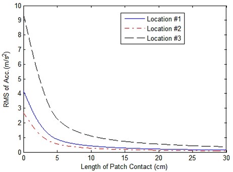
Results in Fig. 2 indicate that analyzed RMS of accelerations on beam decrease when the length of patch contact increases. Results from the bridge-vehicle interaction problem [10] show that the calculated bridge response is only sightly larger than the measurement data by using the point contact model, and by adopting the patch contact model the accuracy of the vibration response of bridge can be improved. In contrast, the vibration response on the beam is greatly affected by the model for simulating the contact between tyre and road surface, e. g. when the patch contact model is adopted with a contact length equal to , the RMS of acceleration on location #2 is equal to , which is only 1/16 of that in the case of point contact with the contact length equal to zero. Therefore to introduce the patch contact model for tyres in the vibration analysis of the beam-vehicle system is of greater significance than in the vibration analysis of the bridge under moving vehicular axle loads.
In order to improve the accuracy of the analyzed vibration response of the beam, apropriate length for the patch contact should be selected in the modeling of interaction between tyres and road surface. Due to the deformation of the tyres, the contact length will vary with the dynamic interaction forces between tyres and road surface, i. e. the contact length is time-dependent. The dynamic interaction forces are generally varying around a mean value due to the excitation nature of the irregular road profile. To simplify the problem, the contact length in this study is assumed to be a contant which can be calculated according to Eq. (15) from the deformation of the two tyres due to the static vehicular axle loads as shown in the right sides of Eqs. (17) and (18) respectively. In this study the length of the patch contact equals to 16 cm and this value will be adopted in further numerical simulations.
3.2. The velocity of vehicle
The velocity of the transportation vehicle will affect the vibration level on the beam structure. Assuming the road grade is B, the RMS of the vibration response at different locations on the beam varying with the vehicle’s velocity is shown in Fig. 3.
Fig. 3RMS of response on beam versus the velocity of vehicle
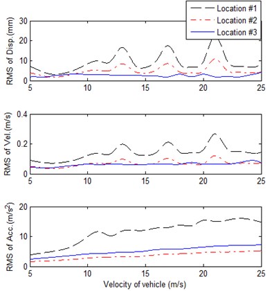
a) The point contact model
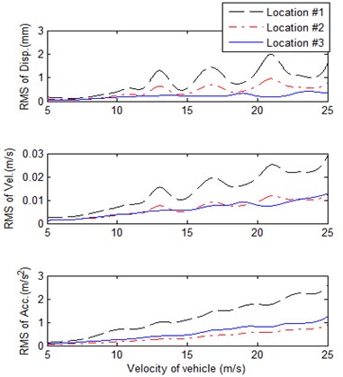
b) The patch contact model
Results show that the analyzed RMS of the vibration response on the beam with point contact model is much larger than that from the patch contact model. In both cases the maximum and minimum RMS of dynamic displacement appears on Locations #1 and #2 respectively, the RMS of velocities on Locations #2 and #3 are equalvalent with different velocities of vehicle, the maximum and minimum RMS of accelerations appear on Location #1 and #3 respectively. The analyzed RMS of the response increases with fluctuations when the velocity of vehicle increases which can be explained as: when the vehicle moves faster, according to Eqs. (7) and (8) for the point contact model or (19) and (20) for the patch contact model, the upper limit of frequency in the excitations increases, which will result in a growth trend in the RMS of the response. The flucturations come from the resonance between the road excitation at a particular velocity of vehicle and the natrual frequencies of the beam-vehicle system.
3.3. The road condition
Table 2RMS of response at different locations with different road grades
Grade of road | A | B | C | D | |
Location #1 | RMS of disp. () | 0.21 | 0.41 | 0.83 | 1.70 |
RMS of vel. () | 0.0036 | 0.0070 | 0.0141 | 0.0283 | |
RMS of acc. () | 0.3573 | 0.7135 | 1.4263 | 2.8550 | |
Location #2 | RMS of disp. () | 0.12 | 0.23 | 0.47 | 0.93 |
RMS of vel. () | 0.0018 | 0.0035 | 0.0071 | 0.0143 | |
RMS of acc. () | 0.0881 | 0.1760 | 0.3543 | 0.7087 | |
Location #3 | RMS of disp. () | 0.09 | 0.17 | 0.35 | 0.70 |
RMS of vel. () | 0.0019 | 0.0038 | 0.0075 | 0.0150 | |
RMS of acc. () | 0.1324 | 0.2657 | 0.5306 | 1.0593 | |
The unevenness of the road profile is the main source of the vibration problems during transportation. To investigate the influence of level of road surface roughness on the vibration level of the beam with the patch contact model adopted, the RMS of the vibration responses of the beam under different road conditions when the velocity of the vehicle is are listed in Table 2. It is noted from the ISO standard that there are mainly four classes of roads graded by A, B, C and D with the roughness coefficient equal to , , and which represent the road conditions as good, average, bad and worse respectively. Results in Table 2 show that the vibration level on the beam increases sigificantly when the road conditions become worse.
3.4. Stiffness of the bracing system
The moving vehicle and the beam-shaped structure on top are connected by braces modeled by spring-damping systems. The stiffness of the braces will affect the propogation of vibration on vehicle body to the beam. This study aims to provide the influence of the stiffness of the brace systems on the vibration level of the beam. To simplify the problem, the stiffnesses of the two braces are assumed to have the same values. When the vehicle travels on a road with Grade B at a speed of , the maximun displacements and the RMS of accelerations at different locations on the beam varying with stiffness of braces are shown in Fig. 4 when the patch contact model is adopted.
Fig. 4Response on beam versus the stiffness of the braces
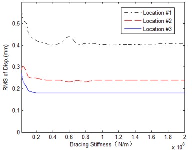
a) The maximum displacement
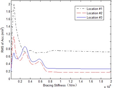
b) The RMS of acceleration
On the perspective of design, the maximum displacement on beam should be small in order to fix the beam-shaped package which requires a relatively large stiffness of the braces. On the other hand, when the braces are very stiff, the vibration level on vehicle and beam at the location of braces tends to be identical, i. e. there is no vibration reduction when the vibration on the vehicle body propogates to the beam on top through the bracing systems, which should also be avoided in the design process. The design of the stiffnesses of bracing systems requires to assure the beam to have both small displacements and low vibration level. Results in Fig. 4 show that the maximum displacement on the beam has a sharp decrease to a converged value when the stiffness of bracing systems increases, the RMS of the acceleration on beam converges to a constant value before several fluctuations and the optimal stiffness can be obtained when the RMS reaches the minimum, which equals to in this study.
4. Conclusions
The equation of motion of a beam-shaped package on moving vehicle under the road excitation is derived in this paper and the vibration analysis is further conducted, which aims to provide references on the condition assessment and vibration control in package transportation. Two different contact models, namely the point contact model and the patch contact model repectively, are adopted to simulate the interaction between tyre and road surface. Numerical simulations are conducted to investigate the influence of the length of patch contact, the velocity of vehicle, the road condition and the stiffnesses of the bracing systems on the vibration level of the beam-shaped structure. Some conclusions are drawn:
(1) The vibration response on the beam is greatly affected by the modeling of the contact between tyre and road surface, the analyzed RMS of accelerations on the beam decreases when the length of patch contact increases. Since the point contact model will lead to an over-estimation on the calculated response, to introduce the patch contact model for tyres in the vibration analysis of the beam-vehicle system is of great significance.
(2) The length of the patch contact model should be carefully selected by the practical vehicular axle loads and the specification of tyres, to guarantee the accuracy of the analyzed vibration response on beam-shaped package.
(3) The analyzed RMS of the vibration response on package increases with fluctuations when the velocity of vehicle increases or the road conditions become worse.
(4) When the stiffness of brace systems increases, the maximum displacement on the beam has a sharp decrease to a converging value, the RMS of the acceleration on beam converges to a constant value before several fluctuations. The opitimal value of the stiffnesses of bracing systems requires the beam to have both small displacements and low vibration level.
References
-
Shi X. M., Cai C. S. Simulation of dynamic effects of vehicles on pavement using a 3D interaction model. Journal of Transportation Engineering, Vol. 135, Issue 10, 2009, p. 736-744.
-
Michialtsos G. T. Bouncing of a vehicle on an irregularity: a mathematical model. Journal of Vibration and Control, Vol. 16, Issue 2, 2010, p. 181-206.
-
Lu F., Ishikawa Y., Kitazawa H., Satake T. Effect of vehicle speed on shock and vibration levels in truck transport. Packaging Technology and Science, Vol. 23, 2010, p. 101-109.
-
Lak M. A., Degrande G., Lombaert G. The effect of road unevenness on the dynamic vehicle response and ground-borne vibrations due to road traffic. Soil Dynamic and Earthquake Engineering, Vol. 31, 2011, p. 1357-1377.
-
Barbosa R. S. Vehicle vibration response subjected to longwave measured pavement irregularity. Journal of Mechanical Engineering and Automation, Vol. 2, Issue 2, 2012, p. 17-24.
-
Ghaith F. A. Nonlinear dynamic modeling of elastic beam fixed on a moving cart and carrying a lumped tip mass subjected to external periodic forces. Proceedings of the ASME 2009 International Design Engineering Technical Conferences & Computers and Information in Engineering Conference, San Diego, California, USA, DETC2009-86318, 2009, p. 1-7.
-
Ragulskis K., Gegeckienė L., Kibirkštis E., Miliūnas V., Zubrickaitė L., Pauliukas A., Ragulskis L. Dynamic study of transportation containers with packages. Journal of Vibroengineering, Vol. 14, Issue 4, 2012, p. 1876-1884.
-
Gwanghum G. Vehicle Dynamic Simulation with a Comprehensive Model for Pneumatic Tyres. Ph. D. Thesis, University of Arisona, 1988.
-
Lyasko M. I. The determination of deflection and contact characteristic of a pneumatic tyre on a rigid surface. Journal of Terramechanics, Vol. 31, Issue 4, 1994, p. 239-246.
-
Yin X. F., Cai C. S., Fang Z., Deng L. Bridge vibration under vehicular loads: tyre patch contact verse point contact. International Journal of Structural Stability and Dynamics, Vol. 10, Issue 3, 2010, p. 529-554.
-
ISO 8606:1995(E). Mechanical Vibration – Road Surface Profiles – Reporting of Measured Data. 1995.
-
Ge F., Qu X. C., Yang S. H., Chen D. K., Zhu Y. Study of selection and relation between tyre air pressure and automobile performance. Journal of Academy of Military Transportation, Vol. 11, Issue 1, p. 53-55, (in Chinese).
-
Wu S. Q., Law S. S. Vehicle axle load identification on bridge deck with irregular road surface profile. Engineering Structures, Vol. 33, 2011, p. 591-601.
About this article

The work described in this paper was supported by a Research Grant from National Natural Science Foundation of China (No. 10902024), Jiangsu Natural Science Foundation (No. BK2010397) and also funded by the Priority Academic Program Development (PAPD) of Jiangsu Higher Education Institutions.
