Abstract
Semi-active suspensions that dissipate energy through controllable dampers have been used in trains, tractors and off-road vehicles in the last decades. Magneto-rheological (MR) fluids have been widely applied as a new material in the field of vibration control. Magneto-rheological (MR) damper is an extremely ideal semi-active control device compared with traditional semi-active damping control device for its superiorities of rapid response (in millisecond), far less response time than sampling time, and almost no time lag caused by the control devices. However, its complicated dynamic hysteresis characteristics vary with the currents imposed on it, resulting in the difficulty in establishing the mathematical model which can truly describe its dynamic behavior. Besides, an effective and precision mathematical model can be of help for constructing the semi-active control law. In this paper, the system identification method based on the theory of fuzzy neural network (FNN) is employed to identify the mathematical model that can accurately reflect the dynamic hysteresis characteristics of magneto-rheological (MR) damper. Under the semi-active control law, the structure on the damper can be stabilized at the fastest rate with an optimal current calculated by the identified mathematical model imposed on magneto-rheological (MR) damper. Consequently, vibration reduction can be effectively realized.
1. Introduction
The mechanical systems involved in many engineering applications are often subject to mechanical excitations that cause unwanted vibrations. In the case of vehicle suspensions, for example, passive dampers could not automatically adjust performances according to the stability for operation or desired human comfort. The semi-active suspensions that dissipate energy through controllable dampers have been used in trains, tractors and off-road vehicles in the last decades [1-2]. In the automotive industry, semi-active suspensions with magneto-rheological (MR) dampers are currently a reality. Such vehicle evolution, from passive suspension to semi-active suspension was achieved as a result of several scientific studies conducted at major research centers [3].
Semi-active control technology has been paid widely attention to and been regarded as one of the most promising technologies for structural vibration reduction in recent years [4]. Both reliability and simplicity are ensured by this technique because it can simultaneously in real time change the structural intrinsic characteristics and achieve state tracking for optimal response by using additional adjustable damping device without huge energy supply. It is better than active control for its excellent fail-safe performance; it can still maintain significant control effect under the condition of energy interruption. Semi-active control systems mainly consist of magneto-rheological (MR) and electro-rheological (ER) damper control systems, active variable stiffness control systems [5], and semi-active fluid damper control systems [6].
The original purpose for researches on magneto-rheological (MR) dampers was to overcome many insurmountable technical bottlenecks of the electro-rheological (ER) dampers, such as low yield shear strength, sensitive to temperature and impurities, and high operating voltage up to several kilovolts. Electro-rheological (ER) fluids and magneto-rheological (MR) fluids were found by Winslow in 1947 [7] and 1949 [8] respectively. Previous researches mainly focused on electro-rheological (ER) fluids, but the semi-active control devices with electro-rheological (ER) fluids have not got practical popularization and application because of its drawbacks mentioned above. However, magneto-rheological (MR) fluids have the following advantages in comparison with the electro-rheological (ER) fluids: (1) Low operating voltage, less energy dependence and better safety; (2) Relatively less environment limitations on machining dampers and applications because it is insensitive to temperature and impurities. (3) The peak yield shear stress of magneto-rheological (MR) fluid’s is one or two orders of magnitude higher than that of electro-rheological (ER) fluid’s, so the device with high damping force peak for vibration reduction and energy dissipation can be produced within limited geometry size. And magneto-rheological (MR) damper has been widely recognized as one of the most promising semi-active control devices by the advantages of large damping force, rapid response, and continuous adjustment in damping force, simple structure, and wide applicability.
The intrinsic strong non-linearity of magneto-rheological (MR) dampers makes it difficult to establish dynamic hysteresis model and to design an effective control algorithm to realize real-time control [9-13]. Although many dynamic hysteresis models have been proposed to describe its intrinsic strong non-linear behavior, the results were not good enough. Stanway [14] introduced the Bingham model which can well simulate the relationship between the damping force and the relative displacement of the piston rod, while the relationship between the damping force and the relative velocity of the piston rod could not be well simulated. Dyke and Spencer [15] put forward a phenomenological model for a magneto-rheological (MR) damper based on the vibration experimental apparatus in 1996 and achieved excellent effect, while the disadvantages still remain for too many identification parameters and complicated calculations in this model. Fuzzy neural system which incorporates the advantages of fuzzy inference and neuron-learning has become popular issues in modeling problems. Combining neural networks with fuzzy set have the advantages of both symbolic and numerical processing. In this paper, fuzzy neural network is employed to identify the dynamic hysteresis model of magneto-rheological (MR) damper under varying currents. The fuzzy neural network was taken as the system identification tool to establish the intelligent identification model, which can truly reflect its complex dynamic hysteresis characteristics from the experimental data by considering all kinds of influential factors. It has high identification precision and is insensitive to noise.
Many scholars have put forward various control algorithms: Dyke [19] put forward clipped-optimal control algorithm; Yi [20] studied the magneto-rheological (MR) damper control algorithm based on the Lyapunov-stability theory; Shiraishi [21] proposed an adaptive neural network algorithm; Guo and Yi [22] established the indirect adaptive control strategy based on neural network. However, many scholars chose the optimal control force calculated by active control algorithm when magneto-rheological damper was imposed on two extreme currents as the damping force [16-18]. The magneto-rheological (MR) damper was treated as a traditional semi-active control device, so it could not make full use of the energy-dissipating capacity of magneto-rheological (MR) damper under varying currents. In this paper, the Bang-Bang control law based on Lyapunov-stability theory was applied to calculate the optimal current on the basis of the intelligent identification model. It can in real time stabilize the structure on the damper at the fastest rate and effectively realize vibration reduction.
2. Theoretical model of fuzzy neural network
Fuzzy logic can be used to describe human experience and knowledge for controller design, but it is short of learning for its fuzzy rule must be provided by experts. Neural network has the ability of learning and memory while it does not guarantee to avoid being trapped in local minima. In addition, the low speed of training and the insignificant weights are still the issues that remain to be solved. Based on the above-mentioned properties, fuzzy neural network (FNN) that combines the advantages of both fuzzy logic and neural network and overcomes their respective deficiencies is adopted to identify the nonlinear behavior of complex systems [23]. In this paper, the T-S fuzzy inference system shown in Fig. 1 can approach any nonlinear system. It is used as a tool to identify the dynamic hysteresis model of MR damper. Neural network is adopted to express and learn this fuzzy inference system. According to the structure of fuzzy inference system shown in Fig. 1, the FNN architecture is designed shown in Fig. 2.
Fig. 1Structure of T-S fuzzy inference system
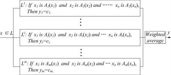
Fig. 2FNN architecture
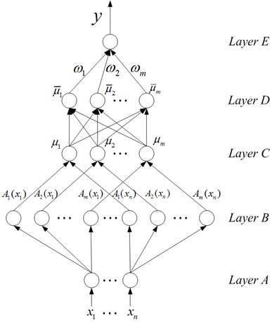
The FNN shown in Fig. 2 has five layers. This is a multiple-input-single-output (MISO) system that owns input linguistic variables and single output . Accordingly, FNN has nodes in layer A and one node in layer E. The input/output mapping is performed by means of fuzzy IF-THEN rules. Each rule consists of a premise part (IF part), comprising the IF precondition which the input variables should fulfill, and the consequent part (THEN part), comprising the inferred outputs. The T-S fuzzy rule of a MISO system can be written as the following form:
where , is the number of T-S fuzzy rules. is the th rule. is fuzzy set, is the number of input linguistic variables. is fuzzy singleton value functioned as the consequent parameters for inference output . Fig. 2 shows a network constructed by the above rules. To give a clear understanding of mathematical function of each node, functions of FNN are described layer by layer below.
Nodes in layer A are input linguistic nodes. The node transmits input variable to layer B. Fuzzification is performed in layer B, so nodes in layer B are called fuzzification nodes and act as membership functions to express the input fuzzy linguistic variables. There are types of membership functions used in this layer. Membership functions on input variables are constructed according to locally spatial mapping property. For input , Gaussian membership functions which locally map the input spatial space to the output space are used, and the mathematical function is:
where and are the center and the width of the Gaussian membership function, respectively. Each node in layer C is called a rule code; it represents a possible If-part for fuzzy rules. The number of rule nodes in this layer is equal to the number of fuzzy sets corresponding to each input linguistic variable. For example, in Fig. 2, if there are rule nodes in layer C, then there are also fuzzy sets in inputs to . The output of each node in layer C is determined by fuzzy AND operation. Here, the product operation is utilized to determine the firing strength of each rule. The function of each rule’s firing strength is:
The normalization computing of firing strength of each rule is performed in layer D, so each node in this layer is called a normalized node. Each node performs weighted average operation, and the function of normalized value of each rule is:
Layer E is corresponding to the consequent part (THEN part) of T-S fuzzy rules, called the defuzzification layer. The node in this layer computes the output signal of the FNN. It acts as a defuzzifier together with the links connected to it. In this paper, the centroid method is employed as the defuzzification tool. The mathematical function is:
where is the optimal parameter of FNN obtained by an effective training algorithm.
3. Identification of dynamic hysteresis characteristics of MR damper based on FNN
Making full use of the excellent properties of MR damper and accurately simulating the complex dynamic hysteresis characteristics are crucial to the control performance of MR damper. In this paper, the system identification method based on the theory of fuzzy neural network is employed to identify the hysteresis characteristics of MR damper. This method can establish high precision intelligent identification model which can truly reflect its complex dynamic hysteresis characteristics. What’s more, the model is insensitive to noise and considers all kinds of influential factors. Experiments were not carried out due to lack of proper experimental conditions, so the revised Bouc-Wen dynamic hysteresis model of MR damper proposed by Xinchun Guan and Jinping Ou [24] is adopted to generate the data samples for system identification.
Fig. 3Revised Bouc-Wen model
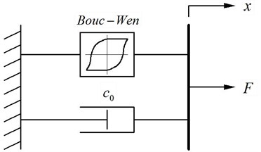
The damping force calculated by the revised Bouc-Wen dynamic hysteresis model is as following:
The hysteretic variable displacement can be calculated by Eq. (7):
The revised Bouc-Wen dynamic hysteresis model was proposed by Xinchun Guan and Jinping Ou on the basis of Spencer and Dyke’s work. In this model, the damping force F is regarded as the sum of viscous force and Bouc-Wen hysteresis damping force, so it can be used to simulate the viscoelasticity of MR fluids under low strain and coulomb characteristics under high strain. The mathematical functions of dynamic hysteresis model of MR damper shows that damping force generated by MR damper is different from traditional viscous damping force; it is not only associated with the relative velocity of the piston rod of damper, but also associated with the relative displacement of the piston rod. Therefore, the damping force generated by MR damper can be expressed as following:
is a nonlinear function expressed by T-S fuzzy logic inference system. According to the theoretical model of FNN mentioned in the second quarter, a T-S fuzzy rule with two-input-single-output is established as following:
where and are the relative displacement and relative velocity of piston rod of MR damper, respectively. is the damping force corresponding to the th rule. The function of the output damping force generated by FNN is:
The process of identification of hysteresis characteristics consists of two parts: learning and examination.
First, learning dynamic hysteresis characteristics of MR damper. MR damper is imposed on a sine wave excitation with amplitude 1.5 cm and frequency 5 Hz under a constant current 2 A. Taking the relative displacement and relative velocity to calculate the corresponding damping force within 2 s according to Eq. (6) and Eq. (7), then taking and as the learning samples for FNN. Each input variable is assigned ten fuzzy sets and simultaneously there are ten T-S fuzzy inference rules. BP algorithm is taken to train the FNN.
Next, after FNN is trained, taking the relative displacement and relative velocity as input samples to test the FNN identification effect, as shown in Fig. 4 and Fig. 5.
Fig. 4Identification effect of response damping force of MR damper under a constant current 2 A
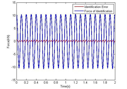
Fig. 5Comparison between the identified and theoretic force under a constant current 2 A
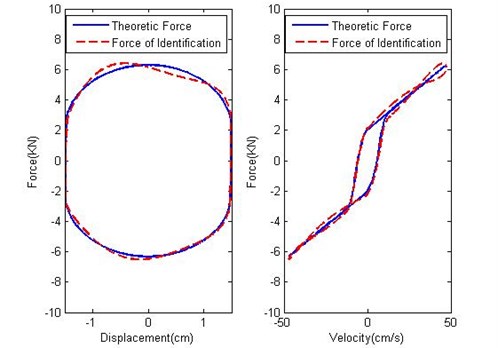
Fig. 4 shows the identification error of MR damping force under a constant current 2 A. The identification error in Fig. 4 is almost zero. Fig. 5 shows the comparison between the identified and theoretic force vs. displacement and velocity respectively under the constant current 2 A. Fig. 4 indicates that the identified damping force is well coincident with the theoretic damping force. Consequently, Fig. 4 and Fig. 5 figure out that the FNN system has mastered the dynamic hysteresis characteristics of MR damper.
FNN is taken as the identification method to identify the dynamic hysteresis characteristics under the current 0, 0.25, 0.5, 0.75, 1.0, 1.25, 1.5, 1.75 and 2 A respectively. The examination indicates that the identification model can truly reflect the dynamic hysteresis characteristics under the corresponding constant current; consequently the model can be applied to design the semi-active control system. The work of this part was conducted off-line. The simulation result shows that more fuzzy rules contribute to better identification effect; but with the number of fuzzy rules increasing, the training time will be longer. In practice, the balance between learning efficiency and training time should be considered.
4. Design of semi-active control
Semi-active control algorithm cannot arbitrarily assign system pole like active control does, so it can only calculate the equivalent control force to approach the force calculated by active control algorithm as much as possible. Only by this means can it achieve the purpose of vibration reduction. The identification method proposed in this paper can be used in real-time control. It can be stored in computer and hardware to design control algorithm because it exists in the form of rule base. The Bang-Bang control law based on Lyapunov-stability theory [25] can be applied to calculate the optimal current on the basis of the intelligent identification model. With the optimal current imposed on MR damper, it can stabilize the structure at the fastest rate. Supported by this technique, the energy-dissipating capacity of MR damper can be completely developed under varying currents in real time and eventually vibration reduction can be easily realized.
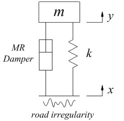
Fig. 6 shows a single degree of freedom system which is a quarter of a suspension system model. A quarter of the suspension system model should be a two degree of freedom system. In order to highlight the technical advantage in the semi-active control, unsprung mass and tyre stiffness are ignored and an ideal single degree of freedom system is adopted as the analysis model. In Fig. 6, is the sprung mass, is stiffness of the damper spring, is the input of road irregularity, and is the response displacement of the sprung mass.
Fig. 6A quarter of the suspension system model
The controlled state function for a quarter of the suspension system model is , the Bang-Bang control law based on Lyapunov-stability theory can be designed as following:
Define the Lyapunov function as: , is a symmetric and positive definite weight matrix determined by Eq. (11).
In Eq. (11) is the identity matrix, then:
Making Eq. (12) to a minimum, it only requires , where is the maximum control force and is the symbolic function.
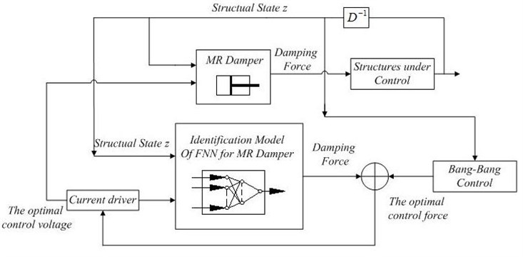
The Bang-Bang control law proposed in this paper can in real time find out the optimal current that is the closest to the current calculated by active control algorithm from the intelligent identification model. A magnetic field is generated by imposing the current on MR damper, so as to have a damping force exerted on the suspension to reduce vibration. The control flow diagram is shown in Fig. 7.
Fig. 7The flow diagram of intelligent semi-active control of MR damper
5. Control simulation
The structural motion function is:
Transform the structural motion function (13) into the state equation:
where , , , .
At each control moment, the Bang-Bang control force can be calculated according to Eq. (11) and Eq. (12).
where is the maximum control force of MR damper under a constant current. The optimal current that is the closest to the corresponding Bang-Bang control force from the intelligent identification model is found out in real-time, and is imposed on the MR damper.
6. Results
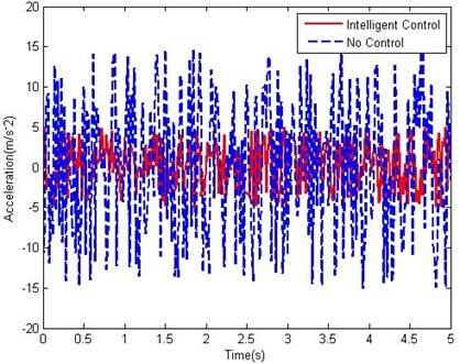
The simulation results (Fig. 8 and Fig. 9) show that the proposed intelligent semi-active control technique for MR damper can effectively control the displacement and acceleration response of vehicle suspension. The displacement response can decrease to 18 % and the acceleration response can decrease to 33 %.
Fig. 8Displacement vs. time
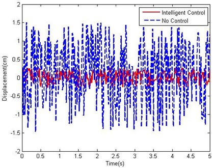
Fig. 9Acceleration vs. time
7. Conclusions
An intelligent semi-active control for vibration reduction of vehicle suspension is proposed in this paper: an intelligent system identification method based on fuzzy neural network is employed to establish the dynamic model that can truly reflect the dynamic hysteresis characteristics of MR damper. The identification model is characterized by high identification precision and insensitive to noise. On the basis of the identification model, an intelligent semi-active control algorithm that can approach the effect of Bang-Bang active control algorithm to the maximum extent is employed to solve the previous problem that the capacity of MR damper couldn’t be fully developed. The proposed method keeps the MR damper on the state of maximum energy-dissipation, which effectively decreases the displacement and acceleration response of vehicle suspension under external excitation. The simulation results verify the validity and practicability of the proposed method. It indicates that the proposed method is a promising semi-active control law for vibration reduction of vehicle suspension.
References
-
Klinger D. L., Cooperrider N. K., Hedrick J. K., White R. C., Cilzado A., Sayers M., Wormley D. Guideway vehicle cost reduction. Parts 1 and 2. National Technical Information Service Reports DT-TST, 1976, p. 75-95.
-
Margolis D., Hrovat D. Semi-active heavy and pitch control of a high seed tracked air cushion vehicle. Intersociety Transportation Conference, Los Angeles-CA, 1976.
-
Lauwerys C., Swevers J., Sas P. Linear control of car suspension using nonlinear actuator control. Proceedings do ISMA2002. Leuven-Belgium, 2002.
-
Nagarajaiah S., Mao Y. Q., Saharabudhe S. Nonlinear, seismic response spectra of smart sliding isolated structures with independently variable MR dampers and variable stiffness SAIVS system. Structural Engineering and Mechanics, Vol. 24, Issue 3, 2006, p. 375-393.
-
Kobori T., Takahashi M., Nasu T. Seismic response controlled structure with active variable stiffness system. Earthquake Engineering and Structural Dynamics, Vol. 22, Issue 11, 1993, p. 925-941.
-
Patten W. N. New life for the Walnut Creek Bridge via semi-active vibration control. Newsletter of the International Association for Structural Control, Vol. 2, Issue 1, 1997, p. 4-5.
-
Winslow M. W. Methods and means for translating electrical impulses into mechanical forces. United States (Patent), No. 2.1947.417.850.
-
Winslow M. W. Induced vibration of suspensions. Journal of Applied Physics, Vol. 20, 1949, p. 1137-1140.
-
Xu Y. L., Qu W. L., Ko J. M. Seismic response control of frame structures use MR/ER dampers. Earthquake Engineering and Structural Dynamics, Vol. 29, 2000, p. 557-575.
-
Wongprasert N., Symans M. D. Seismic response control of nonlinear base isolated structures using variable fluid dampers. Smart Systems and Materials-Smart Systems for Bridges, Structures, and Highways, Newport Beach, USA, 2001 p. 333-344.
-
Yoshida O., Dyke S. J. Seismic control of nonlinear benchmark building using smart dampers. Journal of Engineering Mechanics, Vol. 130, Issue 4, 2001, p. 386-392.
-
Symans M. D., Constantinou M. C. Semi-active control systems for seismic protection of structures: A State-of-the-art review. Engineering Structures, Vol. 21, Issue 6, 1999, p. 469-487.
-
Wang X., Gordaninejad F. Dynamic modeling of semi-active ER/MR fluid dampers. SPIE Conference on Smart Materials and Structures, Vol. 4331, 2001, p. 82-91.
-
Stanway R., Sproston J. L., Stevens N. G. Non-linear modeling of an electrorheological vibration damper. J. Electrostatics, Vol. 20, 1987.
-
Dyke S. J., Spencer Jr B. F. A comparison of semi-active control strategies for the MR damper. Proceedings of Intelligent Information Systems, Bahamas, 1997, p. 580-584.
-
Spencer Jr B. F., et al. Phenomenological Model of a Magneto-rheological Damper. Journal of Engineering Mechanics, Vol. 123, Issue 3, 1996, p. 230-238.
-
Dyke S. J., et al. An experimental study of MR dampers for seismic protection. Smart Materials and Structures, Vol. 7, 1998, p. 693-703.
-
Laura M. Jansen, et al. Semi-active control strategies for MR dampers: comparative study. Journal of Engineering Mechanics, Vol. 126, Issue 8, 2000, p. 795-803.
-
Dyke S. J., et al. Modeling and control of magneto-rheological dampers for seismic response reduction. Smart Materials and Structures, Vol. 5, Issue 5, 1996, p. 565-575.
-
Yi F., et al. Experimental verification of multi-input seismic control strategies for smart dampers. Journal of Engineering Mechanics, Vol. 127, Issue 111, 2001, p. 1152-1164.
-
Shiraishi T., Nakaya N., Morishita S. Structural control by a variable damper using MR fluid. The 6th International Conference on Motion and Vibration Control, Saitama, Japan, Vol. 6, Issue 1, 2002, p. 24-29.
-
Guo D. L., Yi J. Q. Semi-active seismic isolation control based on MR damper and neural networks. The 6th International Conference on Motion and Vibration Control, Saitama, Japan, Vol. 6, Issue 1, 2002, p. 13-18.
-
Shin-ichi Horikawa, Takeshi Furuhashi. On fuzzy modeling using fuzzy neural networks with the back-propagation algorithm. IEEE Trans. on Neural Networks, Vol. 3, Issue 5, 1992, p. 801-806.
-
Xinchun Guan, Jinping Ou. Magneto-rheological damper’s damping force model and the definition of its parameter. Journal of vibration and shock, Vol. 20, Issue 1, 2001, p. 5-8.
-
Yun Zhou, Ping Tan. Control theory and technology for magneto-rheological. Science Press, Beijing, China, 2007.
About this article

This work is supported by the Priority Academic Program Development of Jiangsu Higher Education Institutions (PAPD). Professor Chuwen Guo and Dr. Wei Li in China University of Mining & Technology provided much help on this manuscript. Sincere appreciation is extended to them, and also to the reviewers of this paper for their helpful comments.
