Abstract
Regenerative chatter vibrations may result in shortened tool life and poor surface finish, and hence should be avoided in practice. Since the Spindle Speed Variation (SSV) method has been certified as a feasible and effective way, the issue of speed variation parameters selection has yet to be solved. Based on the discussions of energy accumulation process in chatter and in vari-speed cutting, an analytical method was proposed to select spindle speed variation parameters. The variation of the phase delay between the inner and the outer modulations was regarded as an important argument that reflects the energy accumulation process. Two phase delay related coefficients were proposed for analyzing the mean energy accumulation process and regional energy accumulation enhancement. The importance of spindle acceleration for chatter suppression was also explained. The phase delay based analytical method was verified by numerical simulation and turning experiments.
1. Introduction
Among the methods of chatter prevention, stable cutting parameters prediction and real-time monitoring were well developed. Discrete, analytical [1] and semi-discrete [2] methods have been proposed successively for stable limits prediction. Although the calculation accuracy was gradually improved, the actual chatter prediction may sometimes be ended up in failure due to the diversity and time-varying of machining process. Even short time chatter can make irreversible trauma on workpiece, and cause a considerable economic loss. Therefore, many different methods were proposed for surveillance and reduction of chatter vibration, such as vibrating cutting, control of instantaneous tool-workpiece relative position [3] and varying the spindle speed cutting. Since the method of variable speed cutting has been put forward [4], much effort has been put into effectiveness verification, waveform choosing and side effects analysis. The efficacy of vary spindle speed cutting for chatter suppression has been proved by theoretical and experimental results in available literatures, among which the speed variation waveform was usually be regarded as an important subject. There are many types of speed variation waveform used in practice, such as triangular [5], sinusoidal [6, 7], and random [8] wave. Based on the analysis of energy transmission, Radulescu et al. [6] discussed the chatter suppression efficacy of spindle speed variation. Seguy et al. [5] analyzed the variable spindle speed cutting process in the high-speed domain corresponding to the first flip (period doubling) and to the first Hopf lobes. Their simulation results showed that the effect of speed variation range on chatter suppression was significantly more than that of speed variation frequency. Nevertheless, the determination of such speed variation parameters as spindle speed variation amplitude and/or frequency is difficult to be analyzed quantitatively [9]. Several empirical expressions were presented by Al-Regib et al. [7], discussing the selection principle of the optimum amplitude ratio and the minimum effective frequency of spindle speed modulation. But this empirical method was of high computational complexity. Besides the problem in relation to waveform parameters selection, realization of the spindle speed variation was limited by the response capability of machine tool [10]. Albertelli et al. [11] have investigated the industrial applications, focusing on thermal overload issue of the spindle driving motor. Therefore, the methods of high precision and efficiency are required to determine such spindle speed waveform parameters as variation range and frequency.
Among those prior studies, the influence of spindle speed variation parameters, i.e. amplitude and frequency, on chatter suppression efficacy was investigated with simulations and experiments. However, few theoretical approaches have been published to explain the observed simulation and experiment phenomenon. Therefore, the determination of speed variation parameters is difficult to be analyzed quantitatively.
The purpose of this article is to present an analytical method to quantitatively analyze the problem of parameters selection for spindle speed variation. Although this article focus on the triangular pattern of spindle speed variation, the proposed analysis method would be also suitable for periodic waveforms of other types. In section 2, the cutting process modeling relating to the SDOF (Single Degree of Freedom) cutting system is reviewed for introduction of the phase delay between the inner and the outer modulations. In section 3, the vibration energy transmission of the chattering cutting system is analytically investigated by the discussion of the phase delay variation. The influence of the machine attributions on chatter suppression is also analyzed in this section. Subsequently, the analytical method proposed to analyze the influence of spindle speed variation parameters on chatter suppression is verified through numerical simulations and turning experiments in section 4. Finally, this work will be summarized in section 5.
2. Theoretical background
The phase delay between the outer and the inner modulations is an important conception in the research of regenerative chatter. In addition, its variation plays an important role in vari-speed cutting process for chatter suppression. The following parts of this section depict the characteristics of the phase delay during chatter and chatter suppression process.
Taking the classical SDOF cutting system (see Fig. 1) for example [7, 12-16], the cutting vibration can be formulated as follows:
where represents the cutting force, denotes the time delay between the inner and the outer modulations.
Fig. 1SDOF cutting system with regenerative chatter
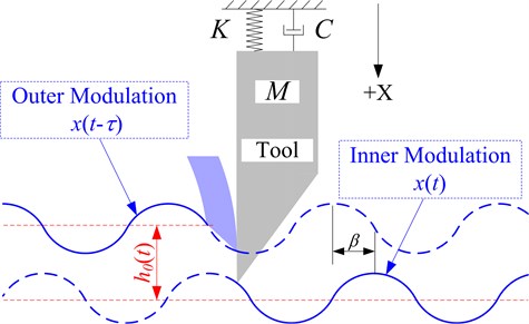
The static cutting force component caused by normal chip thickness (see Fig. 1) has been neglected in Eq. (1). Substitute the mechanical vibration into Eq. (1), the kinematic equation of chatter system becomes [17]:
where indicates the chatter frequency in rad/s, the phase delay between the inner and the outer modulations, the chip width, the cutting force coefficient.
If the cutting parameters fall in the area which results in negative cutting system damping, i.e. , the cutting process becomes unstable, then chatter may emerge and grow with continuous energy input [17]. Therefore a necessary condition for chatter can be derived as that the phase delay should fall in the zones , which are defined as the unstable zones of phase delay. On the contrary, the zones , are defined as the stable zones.
When chatter occurs, it seems like that adjustment of cutting speed to an appropriate value can make changing into a stable range, which might reduce the full developed chatter. However, as vari-speed method is mainly used for chatter suppression in low speed cutting process [18], in which the right spindle speed for stable cutting is hard to be anticipated accurately because of significant influence of process damping [19], slight chatter may be aroused again and aggravated under constant or even slowly varied spindle speed. Therefore, one has to change spindle speed continuously during chatter, keeping to appear in stable and unstable range alternatively and rapidly, to interrupt the continuous process of energy accumulation and hence to suppress chatter. More details about this principle will be discussed herein below.
3. Analysis of vibration energy input during chatter and variable spindle speed cutting process
Continuous energy input is a necessary condition for chatter. The process of energy input into the chatter system and how to be interrupted by vari-speed cutting was analyzed herein below. An introduction to the phase delay realized the analytical method of speed variation parameters selection.
For the conventions of energy analysis, this work was carried out under the following assumptions [20]:
• The machining system is vibrating with a frequency .
• The machining system has a small sinusoidal vibration in chatter process, i.e. .
3.1. Energy input in constant speed cutting process
The work done by cutting force is the source of self-excited vibration energy. Based on the analysis of phase delay, the process of chatter energy input was found out and discussed. In chatter cutting process with constant spindle speed, the work carried out by dynamic cutting force during the time form to can be derived from Eq. (1) as follows:
where:
Since the phase delay is constant, the mathematical expectation of during integer number of vibration cycles is zero, and so as to . Consequently, the work done by cutting force becomes:
During chatter process, the phase delay falls into an unstable zone , , which leading the cutting force to do positive work. The energy produced by the dynamic cutting force will be continuously transmitted into the cutting system, which may result in continuous chatter. If the phase delay is changed into unstable zones, this continuous energy input process can be interrupted.
3.2. Energy input in vary spindle speed cutting process
The purpose of spindle speed variation after the chatter occurred is to disturb the process of energy input, and then to suppress structural vibration. When the spindle speed is changing, the time delay between two consecutive cuts should be substituted by the time-variable one , and the phase delay by . The Eq. (5) indicates that the variation of phase delay directly affect the system energy input, and this energy input process can be suspended when phase delay is changed into stable zones. Thus it can be said that the spindle speed variation parameters affect the chatter suppression efficacy indirectly by influencing the phase delay variation.
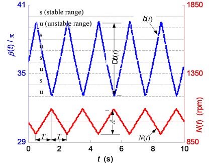
In this article, periodic spindle speed variation was considered, i.e. the spindle speed was modulated periodically according to the given range and acceleration/deceleration time . For convenience in studying the influence of spindle speed acceleration on chatter suppression efficacy, the triangular waveform variation of spindle speed was analyzed in this work, as shown in Fig. 2. The triangular modulation, with the same dynamic characteristics of the spindle, provides larger spindle speed acceleration than the others [21] such as the sinusoidal, random and square-wave modulations.
Fig. 2Relationship between the phase delay βt and the spindle speed Nt
As following, the characteristic of phase delay variation during vari-speed cutting was analyzed. Firstly, the relationship between the mean energy input and the phase delay variation range was discussed. In addition, it was extended to analyze a relationship between the mean energy input and the spindle speed variation parameters (i.e. the spindle speed variation range and the spindle acceleration ). Secondly, the phenomenon of regional energy accumulation enhancement was also seriously considered. Then, influence of the spindle acceleration on chatter suppression efficacy was analytically investigated.
3.2.1. The variation of the phase delay
As the spindle speed was modulated according to the triangular waveform with a variation range and an acceleration/deceleration time , the value of was changed following a similar pattern, but not exactly the same, as shown in Fig. 2 where was calculated by a numerical method with chatter frequency 300 Hz.
Assuming the machining system is vibrating with a frequency [20], the phase delay can be expressed as follows:
where denotes the time cost in the last revolution till present moment. According to the triangular waveform, the maximum and minimum values of can be expressed as follows:
where and in rpm denote the maximum and minimum spindle speeds respectively, and in rpm/s represents the corresponding spindle acceleration expressed by Eq. (8).
It is necessary to note that the acceleration may be time varying for some other type of speed modulations such as sinusoidal wave.
During the time of an acceleration (or deceleration) process, Eq. (6) can be modified as follows:
where denotes the initial spindle speed.
As much less than the time period of spindle speed variation, in Eq. (9) has been usually neglected by the former researchers to calculate an approximate . Moreover, spindle variation range is generally less than 0.4 [6]. Then can be approximated further as follows:
It is indicated by Eq. (10) that the phase delay will be changed following a waveform similar to the spindle speed. This approximation was confirmed by numerical results of Eq. (9) as shown in Fig. 2.
3.2.2. The averaged energy input of the cutting system
Generally, a large number of vibration period may take place during the time of an acceleration/deceleration process. Substitute Eq. (10) into Eq. (4):
As mentioned above, the mathematical expectation of is zero. Then the energy input of the chatter cutting system can be drawn out according to Eq. (3) as follows:
Eq. (12) implies that a positive work will be carried out by the cutting force when falls in the unstable zones , . Or in other word, vibration energy of the cutting system will be increased when falls into the unstable zones , and will be decreased when into the stable zones , .
It should be pointed out that the variation direction of is reversed at the start and end moment of each acceleration/deceleration process, as shown in Fig. 2. The variation range and the middle value of the phase delay were defined as follows:
where , ;, .
During an acceleration/deceleration process as shown in Fig. 2, there are usually more than one stable or/and unstable zones. And the phase delay goes through stable and unstable zones alternatively. Denote the total stable range of by and the total unstable range by , there is . The ratio of stable range to the whole variation range was defined as the stable range ratio
The conclusion can be obtained without proof confirming a large value of the ratio (see Eq. (14)) is favorable to the high performance in chatter suppression.
According to Eq. (13), the stable range ratio can also be defined as the function of and , i.e. . Usually, the middle phase delay mainly depends on the mean spindle speed, and the variation range of phase delay mainly depends on the variation range of spindle speed. A series of values of with different and were calculated out and shown in Fig. 3.
As shown in Fig. 3, along with the increase of , the stable range ratio tends to constant value 0.5 in a waving mode. The shapes of the ratio curve are determined by the middle phase delay , or more exactly, by . As shown in Eq. (15), when , with and when , with the maximum is reached. The maxima points of are obtained when , while the vibration energy input will reach minimal value.
Fig. 3The stable range ratio ξ of the phase delay variation
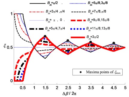
The maxima points of indicate there are two successive stable ranges in the vicinity of each inflection point of , which means a long time for dissipation of vibration energy. More details about this phenomenon are discussed in the third part of this section. Additionally according to Eq. (7) and Eq. (13), it should be mentioned that the middle value and the variation range of the phase delay both are functions of the mean spindle speed , the spindle speed variation range and the spindle acceleration .
The energy input of the cutting system with a constant vibration amplitude was numerically computed under the assumption that the chatter frequency remained unchanged, as shown in Fig. 4 and Fig. 5, where 1000 rpm/s and chatter frequency is 295.8 Hz. Al-Regib et al. [7] have conducted similar simulations and experiments to analyze the energy input by analyzing the spindle speed variation ratio. However, they paid no attention to the phase delay variation range . In this article, Fig. 4 depicts the energy input (see Eq. (3)) and the stable range ratio during the time of a spindle speed variation period, i.e. during the time . The aforementioned conclusion is proved by Fig. 4 that the increase of the stable phase variation range ratio causes a reduction of the energy input of the chatter system, and vice versa. In Fig. 4, the minima points of energy input and the maxima points of stable range ratio have almost the same abscissa values, i.e. the phase variation range . The subtle difference may attribute to the fact that the phase delay between inner and outer modulations cannot trace exactly the same waveform of spindle speed. Corresponding to Fig. 4, 5 shows the spindle speed variation ranges with the maximum, minimum and mean values, i.e. , and . It can be seen that, with a given phase delay variation range , the required spindle speed is influenced by the middle phase delay (or say, ).
Fig. 4Relationship between the stable range ratio ξ and the energy input E
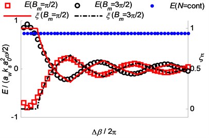
Fig. 5The spindle speed range required by the phase delay variation
Based on Fig. 3-5, it can be found out that: (1) For an allowed variation range of spindle speed ( during vari-speed cutting process for chatter suppression, the maxima speed can be decreased or/and the minima speed increased to make (i.e. and ), by which the stable range ratio reaches a higher value. Therefore, the larger range of spindle speed variation may not mean the higher performance of chatter suppression. (2) Among the maxima points of , the one relating to a smaller has a larger value of , which means higher performance of chatter suppression. (3) In the range of high values of , the stable range ratio trend to the constant value 0.5, which meaning that an excessively enlargement of spindle speed variation range cannot significantly improve the performance of chatter suppression.
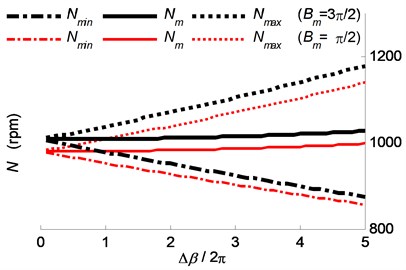
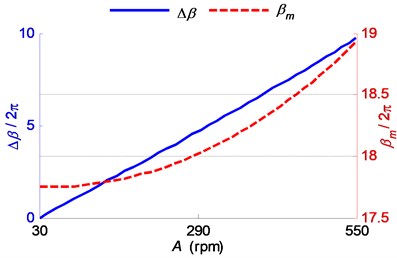
However, in a practical application, the actual mean spindle speed is usually kept constant. Based on this, the energy input of the cutting system was numerically computed, as shown in Fig. 6 where 1000 rpm/s, 1000 rpm and chatter frequency is 295.8 Hz. Fig. 6 depicts the relationship between the work carried out by the cutting force and the spindle speed variation range . The mean cutting force work trends to zero, in a wavelike manner with descending amplitude, as the speed variation range increasing. Correspondingly, the stable range ratio fluctuates with a direction counter to energy input and trends to the constant value 0.5. Fig. 7 depicts the variation range and the middle value of the phase delay, both of which are influenced by the speed variation range combined with the constant mean spindle speed . That is why the shape of the line representing in Fig. 6 is different from the ones in Fig. 3 and Fig. 4.
Fig. 6Relationship between the energy input E and the corresponding stable range ratio
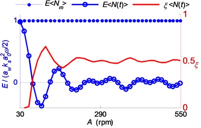
Fig. 7The variation range and the middle value of the phase delay
3.2.3. Regional enhancement of the energy input
According to Eq. (10) and Eq. (12), the energy input can be approximately calculated by Eq. (16) for a given cutting process suffering chatter:
Usually, during a continuous increase/decrease process of the phase delay , there is . Near to the maxima and the minima spindle speed, if the phased delay falls in unstable zone for a relative long time, the vibration may be aggravated instantaneously. This phenomenon is shown in Fig. 8, focusing only on the locations of the inflection points of phase delay.
Fig. 8The location of maxima/minima points of the phase delay βt
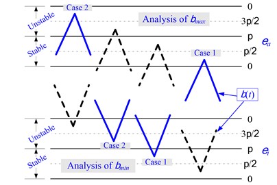
Therefore, and (see Eq. (7)) were set to be the research object in the following cases:
Case 1: In the vicinity of inflection points, falls in the stable zone, i.e. , and for a time relatively shorter than that in the former or the next unstable zone. The vibration energy accumulated in the former unstable zone may not be reduced completely, and then may be enlarged in the following unstable zone.
Case 2: In the vicinity of inflection points, falls in the unstable zone, i.e. , and for a time relatively longer than that in the former or the next stable zone. Therefore, more vibration energy will be accumulated resulting in instantaneous vibration enlargement.
Ignoring the constant coefficients in Eq. (16), the parameters , and were calculated according to Eq. (17) to discuss the instantaneous energy accumulation:
where indicates the initial , the minimal or the maximum , the ending .
In case 1, indicates the energy input during a time between the start of the former unstable zone and the end of the current stable zone. In case 2, indicates the energy input during a time between the start of the current unstable zone and the end of the following stable zone. When neither case 1 nor case 2 occurs, set 0. It shall be obtained that and that can be used as the indicator of regional energy accumulation near to the reflection point of phase delay. Higher value of may mean a worse performance of the vari-speed cutting method for chatter suppression.
3.2.4. Influence of the spindle acceleration
Last but not least, according to Eq. (16), the energy accumulation during the time when the phase delay falls in unstable zone is influenced by the rotation speed , cutting width , cutting force coefficient , overlap coefficient and the spindle acceleration . However, only the spindle acceleration can be controlled in vary spindle speed cutting process. Therefore, the acceleration plays an important role in chatter suppression.
It can be derived from Eq. (16) that the energy accumulation in an unstable zone of the phase delay can be reduced by a larger spindle acceleration . Therefore, high level spindle acceleration may be favorable for chatter reduction and prevention. Nevertheless, the spindle speed variation may aggravate thermal load of the driving system [11]. Additionally, the spindle acceleration is limited by the spindle dynamics such as the rotational inertia and motor capacity [5, 22]. Consequently, there is a maximum acceleration that cannot be exceeded in a given cutting system.
Therefore, a low acceleration is required in vary spindle speed cutting process; otherwise a machine failure may be occurred. On the contrary, a low acceleration may lead to failure chatter suppression, according to the energy discussion in Eq. (16).
4. Verification with numerical simulation and experiments
For the verification of the above discussions, both the numerical and experimental methods were employed to analyze the structural vibration amplitude.
4.1. Verification with numerical simulation
A well-developed cutting process model [17] established upon Eq. (1) was used in this work. The dynamic model was reshaped as shown in Eq. (18):
where denotes the process damping coefficient and the cutting speed.
The influence of the cutting process damping on the cutting force was considered in Eq. (18). Since the work carried out by the damping force is inconspicuously variable because of the limited speed variation, shall not be analyzed in this article. Other influences such as the tool run out and structural nonlinearity were considered in the cutting process simulations. These additional factors would not influence on the aforementioned analysis results.
A series of numerical simulations were conducted with the parameters as shown in Table 1. In order to keep the conditions as close to the real as possible, the test results shown in references [17, 19] were consulted to determine the cutting force coefficients and the structural parameters.
Table 1Simulation parameters
1560 rpm | 1285 MPa | ||
1000 rpm/s | 411 N/mm | ||
0.34 mm | 0.8584 Kg | ||
Feed speed | 0.1 mm/r | 41.2173 N/(m/s) | |
1 | 1.237e6 N/m | ||
Workpiece diameter | 50 mm | ||
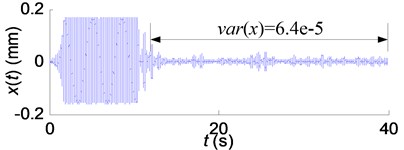
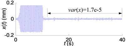
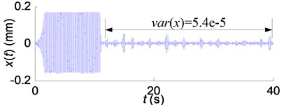
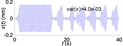
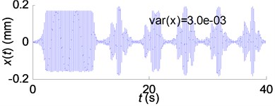
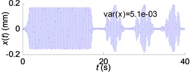
The vibration equation was solved with the fourth order Runge-Kutta method coupled. With low-level random perturbation added in, constant spindle speed was applied at the beginning of the cutting process to excite the chatter. When the chatter occurred with spindle speed 1560 rpm and frequency 206.3 Hz, the spindle speed was modulated in a triangular waveform for the chatter suppression. Fig. 9 depicts some of the simulation results.
Fig. 9 shows that chatter amplitudes were reduced significantly by vari-speed cutting method with the spindle acceleration 1000 rpm/s. The vari-speed cutting process shown in Fig. 9(b) is much stable than that shown in the other two figures.
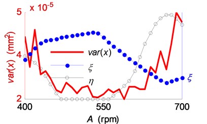
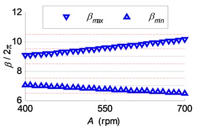
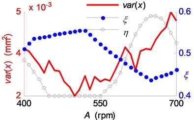
Successively, the variances of the vibration were calculated and compared with the indicating parameters and as shown in Fig. 10(a). The change of reflects the variation trend of chatter intensity.
It can be found out form Fig. 10(a) that the change of the vibration variance inversely follows a trend of the stable range ratio variation. In addition, the stable range ratio plays a more important role than the regional energy accumulation indicator in chatter suppression. However, it seems that the variation trend of variance with the increase of speed variation range lags behind in comparison with that of the stable range ratio. That may be attributed to the influence of the high level of the regional energy accumulation indicator.
Fig. 9Simulation results of the SSV cutting process: a) A= 400 rpm; b) A= 550 rpm; c) A= 700 rpm
(a)
(b)
(c)
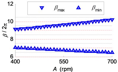
Fig. 10Influence of the spindle speed variation range on the chatter suppression: a) the vibration variance, stable range ratio and regional energy accumulation indicator; b) the phase delay variation ranges in the simulations of SSV cutting process
(a)
(b)
While keeping other parameters constant, the spindle speed acceleration was reduced to 300 rpm/s and a new group of simulations conducted. According to the aforementioned data processing flow, parts of the simulation results were plotted in Fig. 11. Then the variances of the vibration were calculated and compared with parameters and in Fig. 12(b).
Fig. 11Simulation results of the SSV cutting process: a) A= 400 rpm; b) A= 550 rpm; c) A= 700 rpm
(a)
(b)
(c)
Fig. 12The influence of the spindle speed variation range on chatter suppression a) the vibration variance, stable range ratio and regional energy accumulation indicator; b) the phase delay variation ranges in the simulations of SSV cutting process
(a)
(b)
Fig. 11 shows that chatter could not been suppressed by varying spindle speed with acceleration 300 rpm/s. By comparing Fig.10(a) and Fig. 12(a), the conclusions can be drawn out that: (1) the chatter suppression efficacy is closely related to the stable range ratio and the regional energy accumulation indicator . Therefore, these two coefficients can be calculated according to Eq. (14) and Eq. (17) and be used for parameter selection of the spindle speed variation. (2) Spindle acceleration is of crucial importance for chatter suppression by SSV cutting method. SSV cutting process with low spindle acceleration cannot eliminate chatter regardless of the high stable range ratio and the low regional energy accumulation indicator.
4.2. Verification with experiments
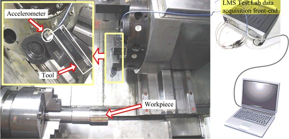
The influence of the stable range ratio , the regional energy accumulation indicator and the spindle acceleration on the chatter suppression efficacy was researched through two groups of turning experiments. Fig. 13 depicts the experimental setup. Although the relative tool-workpiece vibration amplitude is a direct indicator of the chatter intensity, the detection of this item relatively requires more complicated testing equipment and procedures. Moreover, the influence of SSV parameters on chatter suppression efficacy can be expressed by the variation trend of chatter intensity. Therefore, the variation trend of chatter intensity was paid more attention than the absolute vibration amplitude in this paper. In order to monitor the variation trend of chatter intensity, an accelerometer was installed near the tool shank. The acceleration signal was recorded by the LMS Test.lab vibration testing equipment and analyzed with the MATLAB software.
Fig. 13Setup for turning experiments
Although the theory and effectiveness had been affirmed by prior studies, actual implementation of variable speed cutting developed slowly. One of the reasons is that a special integrated module for chatter monitoring and control is required in NC system, which needs high level permission of NC system. The bus based method [23] of the embedded error compensation modular in NC system developed by the authors’ work team was modified, so that it can be used to control the spindle speed in the following experiments.
The cutting conditions are shown in Table 2. The overhang length of the workpiece was set to a large value (i.e. 200 mm), which reduced both the radial dynamic stiffness and the resonance frequency of the workpiece. Considering this fact, it is the workpiece that determines the dynamic characteristics of the whole cutting system. So the chatter occurs with a vibration frequency approximately equal to the workpiece resonance frequency. The relative tool-workpiece displacement fluctuated along an unchanged radial direction of workpiece. Therefore, the SSV parameters selection method proposed based on the analysis of SDOF cutting system, is appropriate to these turning processes.
Table 2Cutting conditions
NC system | HNC-21T | Tool chip | SNMG-PM |
Acceleration time constant | 4 s | Workpiece diameter | 51~45 mm |
Maximum spindle speed | 4000 rpm | Workpiece material | C45E4 (ISO) |
Feeding speed | 0.1 mm/r | Workpiece overhang length | 200 mm |
Cutting depth | 0.2 mm | ||
Each cutting process was finished in a short time, i.e. less than 5 seconds, so that little material was cut off, and the cutting system dynamics were kept almost time-invariance. Constant speed cutting was conducted before each group of experiments to observe the chatter frequency. The actual spindle speed was 999 rpm, and the chatter frequency was 212.5 Hz.
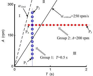
In the first group experiments, the spindle speed variation range was changed from 40 rpm to 260 rpm with an increment equal to 20 rpm, while the acceleration/deceleration time keeping constant. In the second group experiments, the acceleration/deceleration time was changed from 0.4 s to 2 s with an increment equal to 0.1 s, while the spindle speed variation range keeping constant. Fig. 14 depicts the parameters of the applied spindle speed waveform.
Fig. 14The spindle speed variation parameters applied in turning experiments
Acceleration signals were obtained through the accelerometer fixed near the tool shank. For instance, the tool vibration signals, corresponding to the SSV parameters , , and in Fig. 14, are shown in Fig. 15.
The photographs of the machined surfaces, corresponding to the SSV parameters , , and , are shown in Fig. 16. For convenient observation, the pictures were magnified five times in width. Fig. 16(a) and Fig. 16(c) show that the SSV method with improper parameters cannot well reduce the chatter intensity. Actually, the machining quality without a SSV cutting will be even worse, while the proper SSV parameters greatly improves the machining quality as shown in Fig. 16(b) and Fig. 16(d).
Fig. 15The tool vibration signals in SSV cutting process: a) SSV parameter P1 (T= 0.5 s, A= 40 rpm/s); b) SSV parameter P2 (T= 0.5 s, A= 260 rpm/s); c) SSV parameter P3 (T= 2.0 s, A= 200 rpm/s); d) SSV parameter P4 (T= 0.4 s, A= 200 rpm/s)
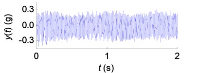
(a)
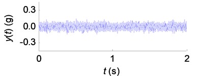
(b)
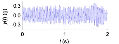
(c)
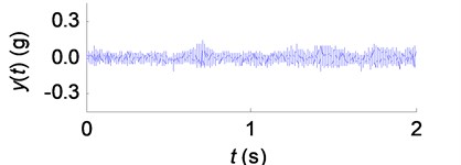
(d)
Fig. 16Machined surfaces in SSV cutting process: a) SSV parameter P1 (T= 0.5 s, A= 40 rpm/s); b) SSV parameter P2 (T= 0.5 s, A= 260 rpm/s); c) SSV parameter P3 (T= 2.0 s, A= 200 rpm/s); d) SSV parameter P4 (T= 0.4 s, A= 200 rpm/s)

(a)

(b)

(c)

(d)
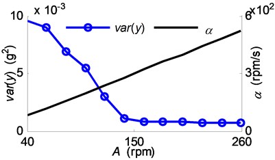
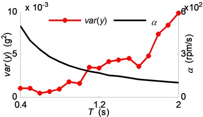
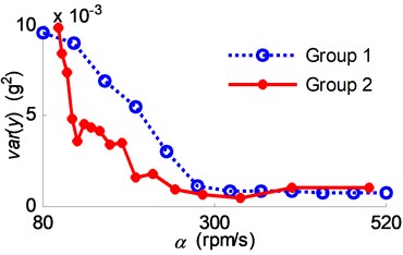
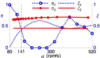
Successively, the variance of the vibration acceleration was calculated and compared with the spindle acceleration , the stable range ratio and the regional energy accumulation indicator as shown in Fig. 17 and Fig. 18. The variance values are shown in Fig. 17(a) relating to the first group experiments, and shown in Fig. 17(b) relating to the second group experiments. Subsequently, the variance values are drawn against the corresponding spindle acceleration in Fig. 18(a). The corresponding coefficients and are drawn in Fig. 18(b), with the subscripts indicating the group indices.
Fig. 18(a) shows that the cutting chatter was fully suppressed in the range of high spindle acceleration (i.e. the zone II between the lines 250 rpm/s and in Fig. 14), while the chatter suppression effectiveness was weaker in the range of lower spindle acceleration (i.e. the zone III under the line ). In the lower spindle acceleration zone, the cutting processes of group 2 have larger vibration variances than that of group 1, which coupled with the phenomena, as shown in Fig. 18(b), that the cutting processes of group 2 have lower stable range ratios when the spindle acceleration 145 rpm/s and have lower regional energy accumulation indicator when 145 rpm/s.
According to Eq. (16) and Fig. 18(b), the experimental results can be explained as that: While the spindle acceleration is kept at a low level, the chatter aroused and kept by the sever energy accumulation, and also would be enhanced by the phenomena of regional energy enlargement and the low stable range ratio. However, the influence of all the factors that would aggravate the energy accumulation were weakened by the increase of spindle acceleration, hence the chatter was suppressed.
Fig. 17Experiment results: a) group 1; b) group 2
(a)
(b)
Fig. 18Experiment results comparison between the two groups of experiments: a) vibration variances; b) phase delay variation
(a)
(b)
In summary, the spindle acceleration plays an important role in variable spindle speed cutting process for the chatter suppression. A high level acceleration , coupled with the phase delay alternating between stable and unstable zones, may be in favor of the chatter suppression. Conversely, when the spindle acceleration is decreased, influence of the stable range ratio and the regional energy accumulation enhancement coefficient on the chatter suppression efficacy may become more distinct.
5. Conclusions
The accumulation of chatter energy in variable spindle speed cutting process was analyzed. Based on an analytical analysis on the variation of the phase delay between the inner and the outer modulations, the influence of spindle speed variation amplitude and spindle acceleration on the chatter suppression efficacy was discussed, taking the triangular spindle speed modulation for example. Numerical simulations and turning experiments were conducted as verification evidence to this work. The proposed analytical research methods may be suitable for the cutting process with the other waveform of spindle speed modulation.
Compared to the studies carried out by the former researchers [7], the influence of phase delay between the inner and the outer modulations on energy accumulation was paid more attention than that of the spindle speed variation range. The direct influence of phase delay variation range on the mean energy accumulation of the chattering cutting system was analyzed. While the speed variation range increased, the mean energy accumulation changed according to a waveform with the descending amplitude.
The phenomenon of regional energy accumulation enhancement in variable spindle speed cutting process was proposed and analyzed. The appearance of this phenomenon may occur in the turning moment of spindle acceleration and deceleration, and may reduce the chatter suppression efficacy.
Though the energy accumulation is influenced by many influencing cutting parameters, only the spindle acceleration can be changed in a given vary spindle speed cutting process. The influence of the spindle acceleration on the chatter suppression was analyzed theoretically and experimentally. The results show that high level spindle acceleration may improve the chatter suppression efficacy.
In conclusion, the chatter suppression efficiency of spindle speed variation can be increased by high level spindle acceleration and suitable spindle speed variation range. When variable spindle speed cutting method is applied, the spindle acceleration should be increased as possible to improve the chatter suppression efficacy. When the spindle acceleration cannot be increased more, especially when falling in a relative low level zone, the speed variation range should be selected carefully considering the proposed method to reduce the mean energy accumulation, and to avoid the phenomenon of regional energy input enhancement.
References
-
Altintas Y., Budak E. Analytical prediction of stability lobes in milling. CIRP Annals – Manufacturing Technology, Vol. 44, Issue 1, 1995, p. 357-362.
-
Insperger T., Stépán G. Stability of the milling process. Mechanical Engineering, Vol. 44, Issue 1, 2000, p. 47-57.
-
Kalinski K. J., Galewski M. A. Chatter vibration surveillance by the optimal-linear spindle speed control. Mechanical Systems and Signal Processing, Vol. 25, Issue 1, 2011, p. 383-399.
-
Takemura T., Kitamura T., Hoshi T., Okushima K. Active suppression of chatter by programmed variation of spindle speed. Annals of the CIRP, Vol. 23, Issue 1, 1974, p. 121-122.
-
Seguy S., Insperger T., Arnaud L., Dessein G., Peigne G. On the stability of high-speed milling with spindle speed variation. International Journal of Advanced Manufacturing Technology, Vol. 48, Issue 9-12, 2010, p. 883-895.
-
Radulescu R., Kapoor S. G., Devor R. E. Investigation of variable spindle speed face milling for tool-work structures with complex dynamics, Part 2: Physical explanation. Journal of Manufacturing Science and Engineering, Transactions of the ASME, Vol. 119, Issue 3, 1997, p. 273-280.
-
Al-Regib E., Ni J., Lee S. Programming spindle speed variation for machine tool chatter suppression. International Journal of Machine Tools and Manufacture, Vol. 43, Issue 12, 2003, p. 1229-1240.
-
Fansen K., Peng L., Xingang Z. Simulation and experimental research on chatter suppression using chaotic spindle speed variation. Journal of Manufacturing Science and Engineering, Transactions of the ASME, Vol. 133, Issue 1, 2011, p. 14502.
-
Wang Q., He N., Li L., Qi B. Y. Present development of the suppression of cutting chatter with varying spindle speed. Machine Building and Automation, Vol. 38, Issue 3, 2009, p. 34-36.
-
Turner S., Merdol D., Altintas Y., Ridgway K. Modelling of the stability of variable helix end mills. International Journal of Machine Tools and Manufacture, Vol. 47, Issue 9, 2007, p. 1410-1416.
-
Albertelli P., Musletti S., Leonesio M., Bianchi G., Monno M. Spindle speed variation in turning: Technological effectiveness and applicability to real industrial cases. International Journal of Advanced Manufacturing Technology, Vol. 62, Issue 1-4, 2012, p. 59-67.
-
Yilmaz A., Al-Regib E., Ni J. Machine tool chatter suppression by Multi-Level random spindle speed variation. Journal of Manufacturing Science and Engineering, Vol. 124, Issue 2, 2002, p. 208-216.
-
Tansel I. N., Wang X., Chen P., Yenilmez A., Ozcelik B. Transformations in machining, Part 2: Evaluation of machining quality and detection of chatter in turning by using s-transformation. International Journal of Machine Tools and Manufacture, Vol. 46, Issue 1, 2006, p. 43-50.
-
Turkes E., Orak S., Neseli S., Yaldiz S. Linear analysis of chatter vibration and stability for orthogonal cutting in turning. International Journal of Refractory Metals and Hard Materials, Vol. 29, Issue 2, 2011, p. 163-169.
-
Ahmadi K., Ismail F. Analytical stability lobes including nonlinear process damping effect on machining chatter. International Journal of Machine Tools and Manufacture, Vol. 51, Issue 4, 2011, p. 296-308.
-
Hajikolaei K. H., Moradi H., Vossoughi G., Movahhedy M. R. Spindle speed variation and adaptive force regulation to suppress regenerative chatter in the turning process. Journal of Manufacturing Processes, Vol. 12, Issue 2, 2010, p. 106-115.
-
Shi H. Metal cutting theory and practice – a new perspecitve. Huazhong University of Science and Technology Press, Wuhan, 2003, (in Chinese).
-
Altintas Y., Engin S., Budak E. Analytical stability prediction and design of variable pitch cutters. Journal of Manufacturing Science and Engineering, Transactions of the ASME, Vol. 121, Issue 2, 1999, p. 173-178.
-
Kurata Y., Merdol S. D., Altintas Y., Suzuki N., Shamoto E. Chatter stability in turning and milling with in process identified process damping. Journal of Advanced Mechanical Design, Systems and Manufacturing, Vol. 4, Issue 6, 2010, p. 1107-1118.
-
Zhang H. Chatter modeling, analysis and control for CNC machining systems. University of Michigan, 1996.
-
Lin S. C., Devor R. E., Kapoor S. G. Effects of variable speed cutting on vibration control in face milling. Journal of Engineering for Industry, Transactions of the ASME, Vol. 112, Issue 1, 1990, p. 1-11.
-
Wei Y. A novel experimental modal analysis of CNC machine tools structure based on movement exciting method. Huazhong University of Science and Technology, 2010, (in Chinese).
-
Yin L., Chen J., Li H., Mao X., Tan B., Liu G. The method of thermal-error compensation embedded in CNC based on bus. Machine Tool and Hydraulics, Vol. 9, Issue 9, 2011, p. 5-7, (in Chinese).
About this article

This work was supported by the grants from Key Projects in the National Science and Technology Pillar Program (No. 2012BAF08B01) and Major State Basic Research Development Program of China (No. 2011CB706803).
