Abstract
The manuscript provides a discussion on the studies and analysis of influence of engine rotational speed to the vibration penetration into the driver via feet. For the driving safety and comfort it is very important what kind and values of vibration are transferred to car body. The motor-engine was chosen as the vibration source. The paper presents some results of investigation on influence of idle gear rotational speed of engine to the vibration registered at place for driver feet. Changes of the values of the influence of vibration on human were presented as RMS and distribution or proposed estimator of spectrum . The changes of the vibration signals and its spectrums were observed in orthogonal 3 axes. The complementary analysis was conducted as time-frequency distribution of the vibration. The experiments were conducted on the car vehicle which was placed on the special test racks. It allows to lessen the road roughens impact on the suspension and the car body.
1. Introduction
The driver’s and passengers’ exposure to whole-body vibration of the vehicle can be determined from short-term body discomfort and long-term physiological damage. The vibration phenomenon occurring on the frame and car-body is one of the main problems of ride comfort. Road surface roughness often acts as a major source that excites the vibration of the vehicle running on the ground through the tire/wheel assembly and the suspension system [1, 2]. There are many more of different vibration sources in vehicles. One of those is motor-car engine. There are some research result published on effects of whole-body vibration and the ride comfort limits [3-7]. There are many reports describing the measurement of the transmissibility of the human body under vibration [8-10]. Some interesting researches were conducted for the low frequency discomfort for human analysed [11].
In many structures such as vehicles and buildings the response of people to the expected vibration must be considered [6]. It is a real challenge in structural design to ensure that the perception threshold level is not exceeded. There exist a lot of publications presenting original methods of vibration signal analysis for many applications [12-25].
In manufacturing of structural components, the type of material used as well as the technology and geometric form are decisive for their service parameters. Currently, there are many studies on new materials and new metallurgical technologies manufacturing processes and repair of steel-making, cast iron and various alloys [26-31]. Considerable emphasis is put on their dynamic properties in designing of machine parts. Tests of dynamic parameters are conducted by application of simulation methods or by active experiments.
2. Identification of the vibration generated by the engine
Motor engine can be considered as one of the vibration generators in vehicles. Rotating machinery such as motors can generate disturbing forces at several different frequencies such as the rotational speed and blade passing frequency. Reciprocating machinery such as compressors and engines can rarely be perfectly balanced, and an exciting force is produced at the rotational speed and at harmonics. Many of physical and chemical phenomena affecting on engine properties [32, 33]. There are two basic types of structural vibration: steady-state vibration caused by continually running machines such as engines, air-conditioning plants and generators either within the structure or situated in a neighbouring structure, and transient vibration caused by a short-duration disturbance such as a lorry or train passing over an expansion joint in a road or over a bridge.
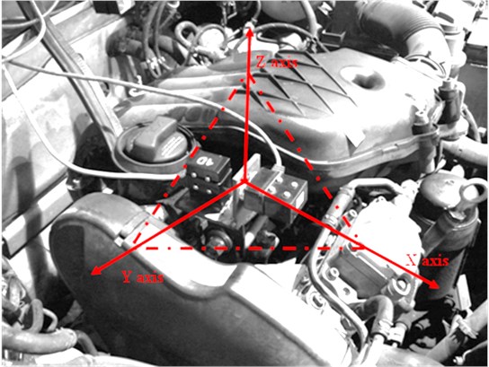
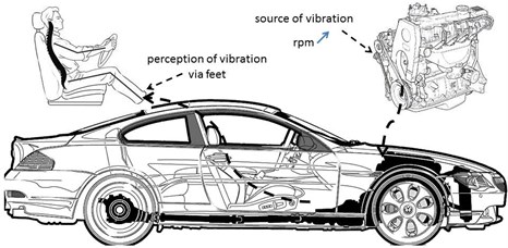
The experimental research was conducted on directional distribution of vibrations generated by the combustion engine [34]. It was used the dual-axis accelerometer. The studies were block of the combustion engine. Under the studies in question, active experiments were undertaken featuring measurements of vibration accelerations in a three directions. It were recorded the vibration in three orthogonal axes . The position and directions of measurements has been depicted in Fig. 1.
Fig. 1Measurement of vibration of combustion engine in 3 directions
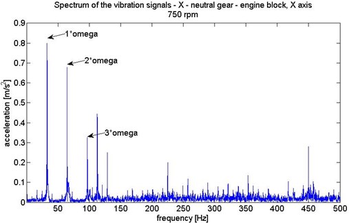
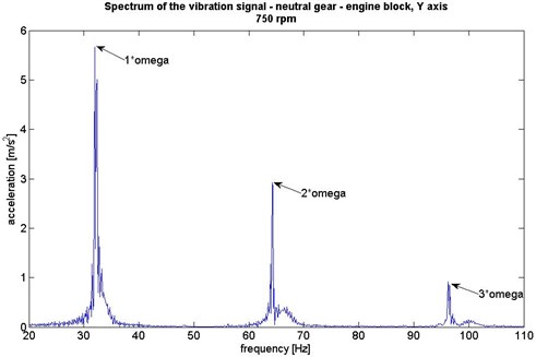
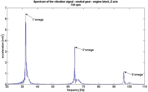
The spectrums of the recorded signals in 3 axes were determined to analyze the structure of motor engine vibration. For the identification of the frequency correlated to rpm (revolutions per minute) of the rotational speed of the engine the figures were analyzed separately with zoom window. The main characteristics frequencies of the engine have been marked on figure 2. Thus the analysis of different between amplitude of the harmonics vibration in axes , and is possible.
3. Research methodology
The scope of research includes active experiment featuring measurements of vibration acceleration in a three directions in location on the floor panel under the driver feet. The vibration in three orthogonal axes were recorded. It enables to analyse the vibration transfer from the source into the driver via feet. These vibrations produce a level of discomfort for the driver. The experiments were conducted on the car vehicle which was placed on the special test racks. It allows eliminate the road roughens impact on the suspension and in result to car body.
The vibration signals, being an effect of a force excitation, obtained by working process of engine, were recorded. The vibration in the vehicle structure were excited by engine working on idle gear. It enables to consider only the vibration generated by vehicle mechanism without vibration from road roughness during the drive. The experiment was conduct under laboratory conditions to ensure reproducibility of results.
Fig. 2Spectrums of vibration of the motor engine in X, Y, Z axes
a)
b)
c)
Fig. 3Scheme of the idea of the research methodology
4. Research results
The results obtained were subsequently processed in the MatLab computational environment. The established scope of research enables to observe changes of the floor panel vibration for idle gear rotational speed increase. The idle gear rotational speed founded during research were: 750 rpm, 1500 rpm, 2000 rpm and 3000 rpm.
The three orthogonal axes were analyzed separately. The comparison of the acceleration of vibration signals allows determine which directions of the vibration propagation is parent and how are changing the vibration under rpm increase.
Based on analysis of the frequency distribution of the engine vibration and conclusion that spectrum of the vibration in and axes (Fig. 2) are very similar the paper presents the results for and axes.
4.1. Analysis of the vibration in time domain
It were established the specific sets of the time courses recorded for the vibration accelerations. Some measurement result obtained for the floor panel with constant rotational speed excitation applied has been depicted in Figures 4 and 5.
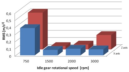
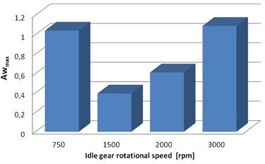
For the purpose of assessing exposure to vibrations of the overall impact on the human body by the vibration of the floor panel of the standing vehicle with working engine the global estimators were calculated. The paper presents the results of the parameter value of vibration dominant effective weighted vibration acceleration determined from the formula 2 and RMS (formula 1) (Fig. 6).
where: – vibration signal, – vibration dominant effective weighted vibration acceleration, – acceleration of vibration in axis, – acceleration of vibration in axis, – acceleration of vibration in axis.
Fig. 4Time function of the floor panel vibration for different rpm, X axis
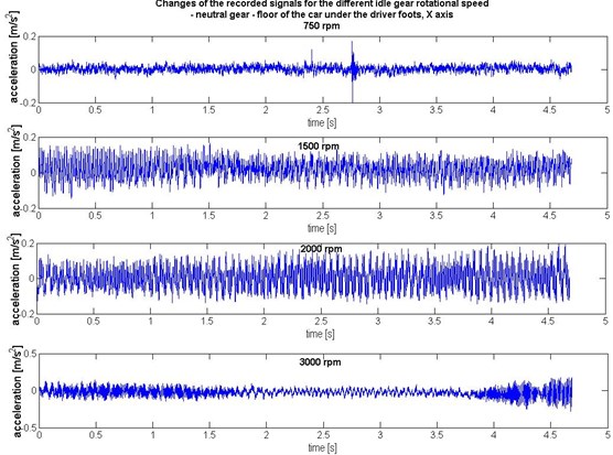
Fig. 5Time function of the floor panel vibration for different rpm, Z axis
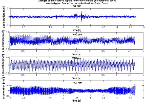
Fig. 6Distribution of the estimators of vibration (in time domain): a) RMS, b) Awmax
a)
b)
Fig. 7Changes of the dynamics of the vibration for the different rpm
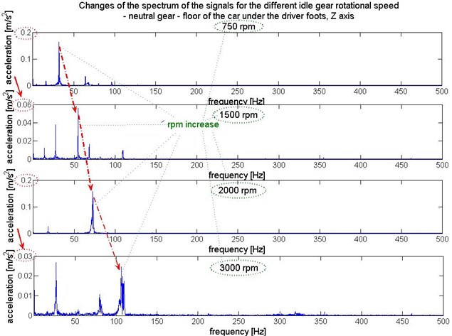
Fig. 8Spectrums of the floor panel vibration for different rpm, X axis
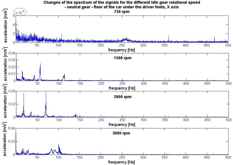
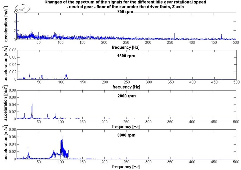
Fig. 9Spectrums of the floor panel vibration for different rpm, Z axis
4.2. Analysis of the vibration in frequency domain
Interesting in above results analysis is that RMS and have larger values for the smallest idle gear rotational speed. To investigate this phenomena the spectrum of the recorded signals in 3 axes were determined to analyze the structure of floor panel vibration. It is possible to observe changes of the dynamics of the vibration for the different rpm transferred in three orthogonal axes (Fig. 7). The frequency components correlated to rpm were indicated in Figure 6. For proper analysis of the vibration amplitude the scale of the axis have to be taken into consider (indicated as the ellipse on axis).
The comparison of the spectrums of floor panel vibration registered under different rotational speed of the engine in and axes directions have been depicted in Figures 8 and 9.
The maximum amplitude of vibration correlated to rpm in range of 1500 to 3000 rpm rises. For the 750 rpm the maximum amplitudes in spectrum are smallest but the signal has a lot of low-energy broadband frequencies components. This may be the reason of higher RMS values.
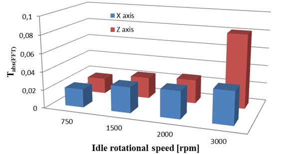
The analysis of vibration signal energy value correlated to frequency distribution based on defined estimator can be more sensitive to exposure and perception on human vibration (Fig. 10). Thus it was proposed the estimator of total energy of vibration spectrum, determined by equation:
Fig. 10Distribution of TabsFFT for the different rpm of engine in X and Z axes
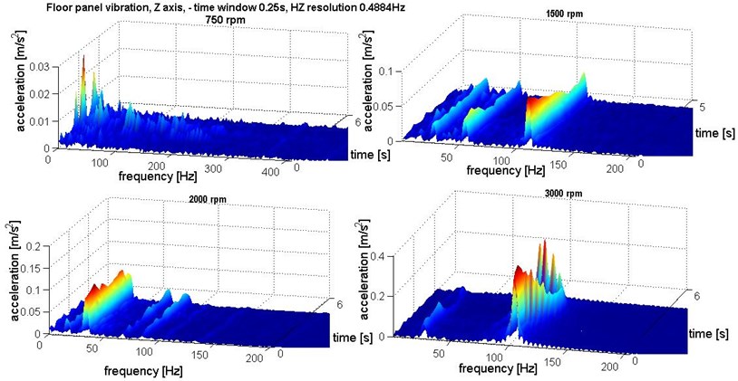
4.3. Analysis of the vibration in time-frequency domains
The registered signals are nonstationary so to analyze the human perception as the exposure to vibration in chosen frequency band the time-frequency transformation have to be made. Therefore, one should observe the distribution of component values of a signal in the domains of time and frequency simultaneously. For that purpose, the signals were transformed by application of the Short-Time Fourier Transform (STFT) according to the following dependence:
where: – window displacement, – analysing frequencies, – constant width of successively analysed window.
The STFT signal distribution has been depicted in Fig. 11-12. It allows observing how long vibration in chosen frequency band is propagating to the structure.
Fig. 11Time-frequency distribution of the floor panel vibration for different rpm – X axis
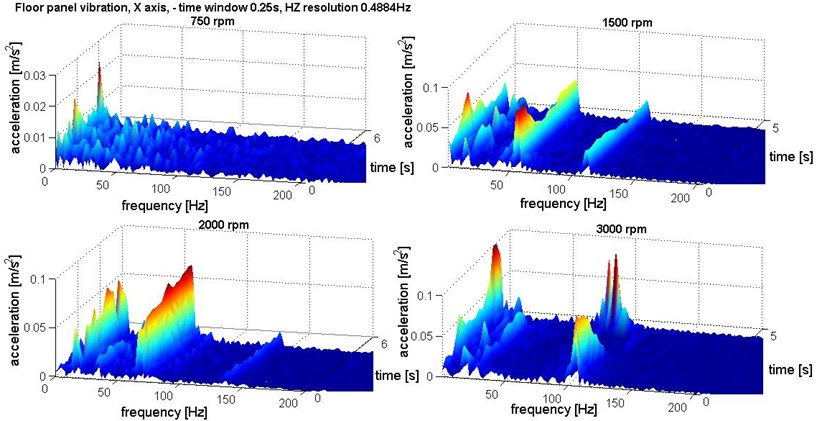
Fig. 12Time-frequency distribution of the floor panel vibration for different rpm – Z axis
5. Conclusions
The obtained results show that increase of the rpm of the motor engine is not directly proportional to generated floor panel vibration. The analysis of the spectrums of the signals allows to clearly identify the frequency components correlated to rpm. It can be assumed that vibration are increased due to increase of rpm.
In conclusion of results analysis some interesting observations were obtained. The vibration penetration into the driver via feet registered on the floor panel have unstable dynamic structure. The RMS values are higher for the vibration under 750 rpm of engine and in range of 1500-3000 rpm some increase tendency can be observed (especially for axis). Based on the spectrums analysis it can be observed that the maximum amplitudes correlated to rpm in range of 1500 to 3000 rpm were raised. For the 750 rpm the maximum amplitudes in spectrum are smallest but the signal has a lot of low-energy broadband frequencies components. This may be the reason of higher RMS and values. After analysis of distribution of estimator of total energy of vibration spectrum it can be assumed that its value is most correlate to the increase of rpm of the engine. Analysis of the time-frequency distribution allows evaluation of the vibration exposure. It is well recognized that for each main frequency components local maximum occurred.
The values of the vibration of the motor engine are much higher than floor panel vibration. This proves good vibration isolation in vehicle cab. It can be observed domination of lower frequencies in the signal registered on vehicle floor panel.
References
-
Wong J. Y. Theory of ground vehicle. 3rd Edition, Wiley, NewYork, USA, 2001.
-
Xua Y. L., Guo W. H. Effects of bridge motion and crosswind on ride comfort of road vehicles. Journal of Wind Engineering and Industrial Aerodynamics, Vol. 92, Issue 7-8, 2004, p. 641-662.
-
ISO 1978: Guide for the evaluation of human exposure to whole-body vibration. 2nd Edition, International Standard 2631-1978(E), International Organization for Standardization.
-
ISO 1997: Mechanical vibration and shock evaluation of human exposure to whole-body vibration. International Standard 2631-1:1997(E), International Organization for Standardization.
-
Griffin M. J. Handbook of Human Vibration. Academic Press Limited, London, 1990.
-
Nader M. Influence of mechanical vibration on the human body in the means of transport and its modeling. Archives of Transport, Vol. 12, Issue 2, 2000, p. 33-53.
-
Lozia Z. Truck front wheels and axle beam vibrations. 5th Mini Conference on Vehicle System Dynamics, Identification and Anomalies, Budapest, 1996.
-
Kubo M., Terauchi F., Aoki H., Matsuoka Y. An investigation into a synthetic vibration model for humans: An investigation into a mechanical vibration human model constructed according to the relations between the physical, psychological and physiological reactions of humans exposed to vibration. International Journal of Industrial Ergonomics, Vol. 27, 2001.
-
Matsumoto Y., Griffin M. J. Dynamic response of the standing human body exposed to vertical vibration. Journal of Sound and Vibration, Vol. 212, Issue 1, 1998.
-
Randall J. M., Mattehews R. T., Stiles M. A. Resonance frequencies of standing humans. Ergonomics, Vol. 40, Issue 9, 1997.
-
Wyllie I. H., Griffin M. J. Discomfort from sinusoidal oscillation in the pitch and fore-and-aft axes at frequencies between 0.2 and 1.6 Hz. Journal of Sound and Vibration, Vol. 324, 2009.
-
Bajkowski J., Jasiński M., Mączak J., Radkowski S., Zalewski R. The active magnetorheolo-gical support as an element of damping of vibrations transferred from the ground to large-scale structure supports. Key Engineering Materials, Vol. 518, 2012, p. 350-357.
-
Burdzik R., Stanik Z., Warczek J. Method of assessing the impact of material properties on the propagation of vibrations excited with a single force impulse. Archives of Materials and Metallurgy, Vol. 57, Issue 2, 2012, p. 409-416.
-
Burdzik R. Material vibration propagation in floor pan. Archives of Materials Science and Engineering, Vol. 59, Issue 1, 2013, p. 22-27.
-
Burdzik R. Monitoring system of vibration propagation in vehicles and method of analysing vibration modes. J. Mikulski (ed.): TST 2012, CCIS 329, Springer, Heidelberg, 2012, p. 406-413.
-
Burdzik R. Research on structure and directional distribution of vibration generated by engine in the location where vibrations penetrate the human organism. Diagnostyka, Vol. 14, Issue 2, 2013, p. 57-61.
-
Burdzik R., Konieczny Ł., Łazarz B. Influence of damping characteristics changes on vehicles vibration research. 19th International Congress on Sound and Vibration (ICSV19), Conference proceedings, 2012, p. 657.
-
Jasinski M., Radkowski S. Use of the higher spectra in the low-amplitude fatigue testing. Mechanical Systems and Signal Processing, Vol. 25, Issue 2, 2011, p. 704-716.
-
Michalski R., Wierzbicki S. An analysis of degradation of vehicles in operation. Maintenance and Reliability, Vol. 1, Issue 37, 2008, p. 30-32.
-
Cempel C. Decomposition of the symptom observation matrix and grey forecasting in vibration condition monitoring of machines. International Journal of Applied Mathematics and Computer Science, Vol. 18, Issue 4, 2008, p. 569-579.
-
Dąbrowski Z., Dziurdź J., Klekot G. Studies on propagation of vibroacoustic energy and its influence on structure vibration in a large-size object. Archives of Acoustics, Vol. 32, Issue 2, 2007, p. 231-240.
-
Dąbrowski D., Cioch W. Neural classifiers of vibroacoustic signals in implementation on programmable devices (FPGA) – comparison. Acta Physica Polonica, Vol. 119, Issue 6a, 2012, p. 946-949.
-
Engel Z. W., Kowalski P. Investigation of the influence of simultaneous vibroacoustic exposures on the operator. Journal of the Theoretical and Applied Mechanics, Vol. 46, Issue 4, 2008, p. 799-811.
-
Urbanek J., Barszcz T., Zimroz R. Application of averaged instantaneous power spectrum for diagnostics of machinery operating under non-stationary operational conditions. Measurement, Vol. 45, Issue 7, 2012, p. 1782-1791.
-
Ragulskis K., Kanapeckas K., Jonušas R., Juzėnas K. Vibrations generator with a motion converter based on permanent magnet interaction. Journal of Vibroengineering, Vol. 12, Issue 1, 2010, p. 124-132.
-
Kusiński J., Kac S., Kopia A., Radziszewska A., Rozmus-Górnikowska M., Major B., Major L., Marczak J., Lisiecki A. Laser modification of the materials surface layer – a review paper. Bulletin of the Polish Academy of Sciences Technical Sciences, Vol. 60, Issue 4, 2012, p. 711-728.
-
Fornalczyk A., Saternus M. Platinum recovery from used auto catalytic converters in electrorefining processs. Metalurgija, Vol. 52, Issue 2, 2013, p. 219-222.
-
Oleksiak B., Blacha-Grzechnik A., Siwiec G. Application of the flotation process in the silver recovery from the wastes generated during the silvery semi-products manufacturing. Metalurgija, Vol. 51, Issue 3, 2012, p. 298-300.
-
Blacha L, Burdzik R, Smalcerz A, Matuła T. Effects of pressure on the kinetics of manganese evaporation from the Ot4 Alloy. Archives of Metallurgy and Materials, Vol. 58, Issue 1, 2013, p. 197-201.
-
Blacha L., Łabaj J. Factors determining the rate of the process of metal bath components evaporation. Metalurgija, Vol. 51, Issue 4, 2012, p. 529-533.
-
Węgrzyn T., Piwnik J., Łazarz B., Hadryś D. Main micro-jet cooling gases for steel welding. Archives of Materials and Metallurgy, Vol. 58, Issue 2, 2013, p. 551-553.
-
Dzida M., Jężak S., Sumara J., Żarska M., Góralski P. High pressure physicochemical properties of biodiesel components used for spray characteristics in diesel injection systems. Fuel, Vol. 111, 2012, p. 165-171.
-
Kaźmierczak-Bałata A., Bodzenta J., Trefon-Radziejewska D. Determination of thermal-diffusivity dependence on temperature of transparent samples by thermal wave method. International Journal of Thermophysics, Vol. 31, Issue 1, 2010, p. 180-186.
-
Burdzik R., Czech P., Konieczny Ł., Wojnar G. Analysis of directional distribution of vibrations generated by the combustion engine. Journal of Polish CIMAC Energetic Aspects, Vol. 7, Issue 1, 2012, p. 27-32.
About this article

