Abstract
The main objective of this paper is to provide the methods and techniques to test and improve the design and manufacturing ability of electric scooter. This research study focuses on the steering mechanism, transmission mechanism and carrying structure parts. In this investigation, we will estimate the effects of flexibility of the flexible steering mechanism, transmission mechanism and carrying structure on the computation of the dynamic steering, transmission forces and responses. By using the computational ability and simulation of modern computers and CAE (Computer-Aided Engineering) softwares, the dynamic responses, dynamic stress distribution and modal tests can be calculated and performed. These data can be used as the design and manufacturing references of corresponding manufacturers. For the modal analysis, the impact hammer, data recorder, accelerometer, laser optical displacement sensor, spectrum analyzer and dynamic simulation software can be applied on the key parts of the electric scooter to perform the vibration modal and dynamic analysis.
1. Introduction
Energy applications of electric vehicles require power plants, power transmission and distribution. For conversion steps such as charging, due to high electric motors operating efficiency of internal combustion engines and aggregate energy efficiency of electric vehicles. Electric vehicles are compared with internal combustion engine vehicles with more than 70 % energy saving. With the arrival of the aging society, the demand of electric scooter is increasing. From 2002 to 2010, annual exports of electric scooter of Taiwan averaged about 220.000 vehicles. Taiwan becomes the major electric scooter production country in the world. The dynamic rigidity design of steering mechanism, transmission mechanism and supported structure for electric scooter has a big effect on steering efficiency of movement and load capacity [1]. Although Taiwan in the design and manufacture of electric scooter has reached a certain level, it is important to improve the steering mechanism, transmission mechanism and carrying structure designing, testing and analysis abilities. Actually, the dynamic rigidity of electric scooter does not have a systematic approach. This study mainly focus on the design of steering mechanism and transmission mechanism of electric scooter with dynamic rigidity analysis of load bearing structure in order to improve testing the electric scooter’s dynamic behavior of the entire structure and mechanisms [2].
In the theoretical and numerical analysis of the rigid and flexible parts of steering mechanism, transmission mechanism and carrying structure, the model will be considered the first six elastic modes for each of the torsional vibration and flexural vibration [3]. The finite element model on flexible components is set up for finite element analysis software, then the flexible components data are loaded into dynamic analysis software to perform the dynamic responses and the stress distribution of the steering mechanism, transmission mechanism and carrying structure. Simultaneously, dynamic steering, transmission forces and responses of electric scooter will be calculated with the case of elastic deformation and can be compared with the case without considering the factor of elasticity [4-5]. Experimental measurements from the modal test will be used to verify the theoretical and numerical analysis [6].
2. Electric scooter’s real and CAD models
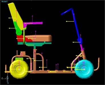
The CAD (Computer-Aided Design) models were created by Solid Edge software according the dimensions of real electric scooter vehicle model as shown in Figure 1 and Figure 2. How to quickly and efficiently verify the value of prototype by virtual models is the most valuable issue. Due to many variables that affect electric scooter operation efficiency, so take advantage of CAE model analysis, parameter experiments and modal analysis. It is useful in identifying optimal parameter design, and it also can be used as reference for testing and manufacturing process development.
Fig. 1The real model of electric scooter
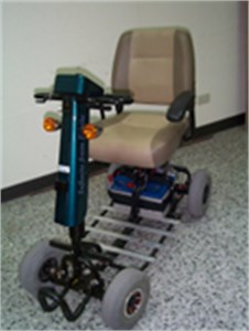
Fig. 2The CAD model of electric scooter
3. Computer-aided engineering techniques
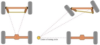
Steering mechanism is widely used in the automotive, truck and transport devices. In general, it is installed in between the wheel and directional control components. The main purpose, as the driving direction of rotation control components, makes the wheel with vertical axis of rotation and change the direction of scooter’s motion. There are many types of steering mechanism, the most common are the drag link steering linkage, parallelogramsteering linkage, rack and pinion steering linkage and rocker-type steering mechanism. Most manual or hydraulic power-assisted steering mechanism used to control the steering. So when hydraulic power source failure, you can still manually operated, power steering reduces manual operations involved heavy work. If it is power steering pump via belts connected to the crank shaft, the engine will be turning and turning. Ackermann steering is for vehicles with a power usually by means of differential gear or connecting linkage to control the direction of the vehicle, when the car turned and all wheels follow to the same circle in a circular motion. When steering, vehicle does not slip, it extends these axle center line must intersect at a point. This is the principle of Ackermann steering. For example, when the front wheels must be parallel to each other. But when the car turns, the inside front wheel lateral deflection angle is larger than the front wheels. General speaking, the turning radius is the point of maximum deflection, distance between lateral, front and Center as shown in Figure 3. In General, Ackermann steering wheel is knuckle arm inward and backward. Tilt angle depending on wheelbase and track width of the car tread. Wheelbase is the distance between front and rear wheel, that is, two front wheels touching the ground after online with two rounds of online distance. If the car has two rear axles, then the reference point is the midpoint of the two rear axle distance. Wheelbase is the distance of the two front or two rear wheels, which is two wheels (front or rear) ground line length as shown in Figure 4.
Fig. 3All wheels rotate around center
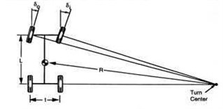
Fig. 4Tilt wheel steering arm change direction
4. Dynamic behavior on steering mechanism
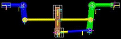
Main purpose of steering mechanism for driving direction of rotation control components is to make the wheel with vertical axis of rotation and change the direction of scooter’s motion. When a scooter has to turn right or turn left fully, non-constant-ratio steering mechanism achieves a quick response. The entire link is operated by steering rocker shaft axis. The motion is passed to the steering linkage with the ball joint connection between the connecting rod which was performed by RecurDyn (Recursive Dynamic software) as shown in Figure 5. A scooter with a steering geometry chosen for low-speed (Ackermann) will not be as effective at higher vehicle speeds. In a high speed turn, the inside tire will have a lower normal force, which means it could achieve the same amount of lateral cornering force with a smaller slip angle. Using Ackermann will result in more instances in which the inside tire is dragged along at too high a slip angle, unnecessarily raising the temperature and slowing the vehicle down with excessive slip induced drag.
Fig. 5Dynamic analysis of scooter parallelogram steering mechanism
5. Stress/strain and modal analysis
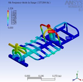
In order to build up the steering mechanism, actuator model, we ignore the geometry of the bolt hole and stereo elements to fit analysis. Turning and torsional mode and flexural modes of drive shaft coupling is performed by the finite-element analysis method. In order to fit the Steering and drive shaft of solid elements, each element of the transverse slope deformation of torsional vibration for the associated element has to split link to pinned-pinned element. Constructing steering and the flexible drive shaft components are based on finite element method analysis calculations, the displayed graphics of stress distribution. The FEM (Finite Element Method) modal analysis is performed by ANSYS Workbench for the scooter’s product lifecycle management (PLM) including main structure and mechanical deformation of the following scenario as shown in Figure 6 to Figure 11. The majority of structures can be made to resonate, i.e. to vibrate with excessive oscillatory motion. Resonant vibration is mainly caused by an interaction between the inertial and elastic properties of the materials within a structure. Resonance is often the cause of, or at least a contributing factor to many of the vibration and noise related problems that occur in structures and operating machinery. To better understand any structural vibration problem, the resonant frequencies of a structure need to be identified and quantified. Today, modal analysis has become a widespread means of finding the modes of vibration of a machine or structure. In every development of a new or improved mechanical product, structural dynamics testing on product prototypes is used to assess its real dynamic behavior. Modes are inherent properties of a structure, and are determined by the material properties (mass, damping, and stiffness), and boundary conditions of the structure. Each mode is defined by a natural (modal or resonant) frequency, modal damping, and a mode shape (i.e. the so-called “modal parameters”). If either the material properties or the boundary conditions of a structure change, its modes will change. For instance, if mass is added to a structure, it will vibrate differently [7].
Fig. 61st mode of scooter’s main structure (134 Hz)
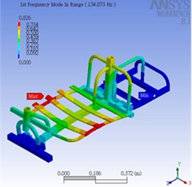
Fig. 72nd mode of scooter’s main structure (170 Hz)
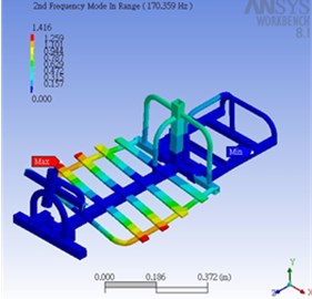
Fig. 83rd mode of scooter’s main structure (266 Hz)
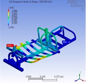
Fig. 94th mode of scooter’s main structure (272 Hz)
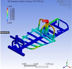
Fig. 105th mode of scooter’s main structure (318 Hz)
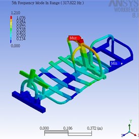
Fig. 116th mode of scooter’s main structure (337 Hz)
6. Experimental modal analysis (EMA)
Experimental modal analysis is the process of determining the modal parameters (natural frequencies, damping factors, modal vectors, and modal scaling) of a linear, time-invariant system. The modal parameters are often determined by analytical means, such as finite element analysis. One common reason for experimental modal analysis is the verification or correction of the results of the analytical approach. Often, an analytical model does not exist, and the modal parameters determined experimentally serve as the model for future evaluations, such as structural modifications. Predominantly, experimental modal analysis is used to explain a dynamics problem (vibration or acoustic) whose solution is not obvious from intuition, analytical models, or previous experience. The process of determining modal parameters from experimental data involves several phases. The success of the experimental modal analysis process depends upon having very specific goals for the test situation. Every phase of the process is affected by the goals which are established, particularly with respect to the errors associated with that phase [8-9]. The experimental modal analysis and simulation will be performed by LDS Dactron spectrum analyzer, accelerometers, impact hammer and ME’scope software. The experimental modal analysis for the scooter’s main structure is shown in Figure 12-17. The modal frequency results obtained by using FEA (Finite Element Analysis) and modal experiments are shown in Table 1.
Fig. 121st mode of scooter’s main structure (133 Hz)
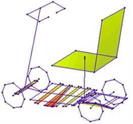
Fig. 132nd mode of scooter’s main structure (169 Hz)
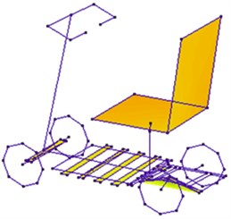
Fig. 143rd mode of scooter’s main structure (264 Hz)
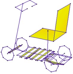
Fig. 154th mode of scooter’s main structure (273 Hz)
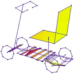
Fig. 165th mode of scooter’s main structure (319 Hz)
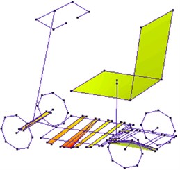
Fig. 176th mode of scooter’s main structure (335 Hz)
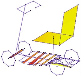
Table 1Modal frequency results obtained by using FEM and modal experiments
Mode No. | ANSYS (Hz) | Experiment (Hz) | Absolute difference (%) |
1st mode | 134 | 133 | 0.75 |
2nd mode | 170 | 169 | 0.59 |
3rd mode | 266 | 264 | 0.76 |
4th mode | 272 | 273 | 0.37 |
5th mode | 318 | 319 | 0.31 |
6th mode | 337 | 335 | 0.6 |
#Relative difference between the ANSYS and Experiment frequencies. | |||
7. Dynamic road test
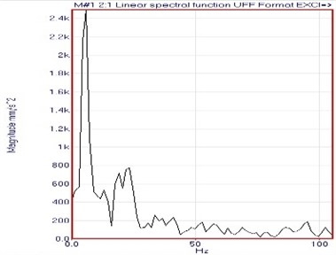
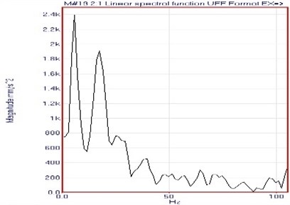
In order to verify the validation between the CAE and real models, we performed the road test to monitor the dynamic behaviors and responses with different driving conditions. In the CAE model, the RecurDyn software was used to perform the analysis and simulation. The FFT (Fast Fourier Transform) dynamic response of scooter’s underseat from RecurDyn (CAE model) with the driving speed 3.6 km/hr is shown in Figure 18. The FFT dynamic response of scooter’s underseat from ME‘scope (Experiment model) with the driving speed 3.6 km/hr is shown in Figure 19. The results show that both curves are very similar in frequency and magnitude ranges.
Fig. 18FFT from RecurDyn (underseat)
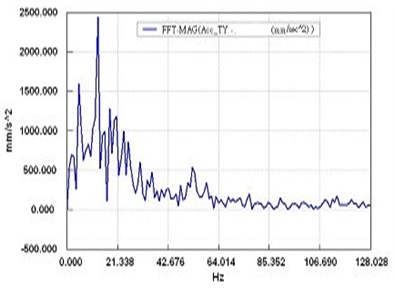
Fig. 19FFT from experiment (underseat)
The FFT (Fast Fourier Transform) dynamic response of scooter’s main structure from RecurDyn (CAE model) with the driving speed 3.6 km/hr is shown in Figure 20. The FFT dynamic response of scooter’s main structure from ME‘scope (Experiment model) with the driving speed 3.6 km/hr is shown in Figure 21. The results show that both curves are very similar in frequency and magnitude ranges.
Fig. 20FFT from RecurDyn (main structure)
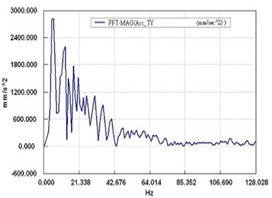
Fig. 21FFT from experiment (main structure)
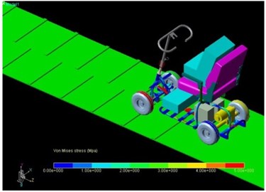
Durability testing is the assessment criteria for each model must execute. Its purpose is to examine each of the components of the vibration and shock effect of the existence of life defects. Because test cycle of road test is long and extremely expensive, computer simulation analysis becomes very meaningful. During parts durability analysis, we must first accurately obtain parts of load time histories, which requires accurate dynamic simulation analysis. However, for such a complex dynamic system, the previous simulation analysis difficult to give satisfactory results, making the durability of performance can only be determined by experiment. In order to verify RecurDyn electric scooter dynamic simulation results in durability analysis on the feasibility of the model in the case of road conditions through the barrier impact acceleration simulated. The results are replicated on the timeline and you can load as durability testing time history data. By viewing dynamic stress distribution, the frame can be learned through the obstacles generated by the force of each part of the road test case.
For this 3D structure, the use of ANSYS meshing in the parameter setting is very complex and easily making mistakes. Therefore, we choose to mesh by using ANSYS Workbench for modal analysis. In order to observe the RecurDyn dynamic stress distribution, you need to use ANSYS generated several files. We will import into ANSYS Workbench to mesh the structures, then switch to ANSYS to perform modal analysis to produce the desired files. If the CAE model only import to ANSYS for stress and strain analysis, you must first calculate the load and force. While using RecurDyn for dynamic stress analysis, we can simply set the quality of the components which were calculated by a computer. The dynamic stress distribution and road test with equivalent loads are shown in Figure 22 and Figure 23. Consequently, the stress history graph and stress calculations for complex structures are quite convenient through these procedures developed in this investigation.
Fig. 22Dynamic stress distribution
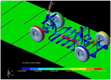
Fig. 23CAE road test with equivalent loads
8. Summary and conclusions
Software tools that have been developed to support these activities are considered CAE tools. CAE tools are being used, for example, to analyze the robustness and performance of components and assemblies. The term encompasses simulation, validation, and optimization of products and manufacturing tools. In the future, CAE systems will be major providers of information to help support design teams in decision making. CAE tools are very widely used in the industry. In fact, their use has enabled the manufacturers to reduce product development cost and time while improving the safety, comfort, and durability of the vehicles they produce. The predictive capability of CAE tools has progressed to the point where much of the design verification is now done using computer simulations rather than physical prototype testing. CAE dependability is based upon all proper assumptions as inputs and must identify critical inputs. Even though there have been many advances in CAE, and it is widely used in the engineering field, physical testing is still used as a final confirmation for subsystems due to the fact that CAE cannot predict all variables in complex assemblies (i.e. metal stretch, thinning). In this paper, the computer-aided engineering analysis softwares of RecurDyn and ANSYS Workbench are used for dynamic analysis and simulation. Simulation results showed that using RecurDyn with ANSYS Workbench softwares in dynamic analysis of electric scooter achieves a good effect. The experimental modal analysis and simulation is also performed by LDS Dactron spectrum analyzer, accelerometers, impact hammer and ME’scope software. Therefore, CAE softwares and appropriate vibration measurement hardwares can be used on the highly complex system to take advantage of dynamic and modal analysis technology in real practical applications. It also can be effective for product quality in the design, product reliability and effectiveness in the future.
References
-
Wang Y., Wang Z. A time finite element method for dynamic analysis of elastic mechanisms in link coordinate systems. Computers and Structures, Vol. 79, 2001, p. 223-230.
-
Hodgetts D. The whirl modes of vibration of a crankshaft. IMechE, 1976, p. 255-261.
-
Heat A. R., McNamara P. M. Crankshaft stress analysis – the combination of finite element and classical analysis techniques. ASME ICE Engine Design Operation and Using Computer Systems, Vol. 9, 1989, p. 57-64.
-
Zhang S., Wen H., Huang Y. M., Hu D. J. Modeling and analysis method of dynamical characteristics for a whole machine tool structure. Journal of Shanghai Jiaotong University, Vol. 35, Issue 12, 2001, p. 834-1837.
-
Zhang G. P., Huang Y. M., Shi W. H., Fu W. P. Predicting dynamic behaviors of a whole machine tool structure based on computer-aided engineering. International Journal of Machine Tools and Manufacture, Vol. 43, Issue 7, 2003, p. 699-706.
-
Ewins D. J. Modal testing: theory and practice. Research Studies Press Ltd., Letchworth Hertfordshire, England, 1984.
-
Akio N. State of art on modal analysis in Japan. Proceedings of the 10th International Modal Analysis Conference, 1992, p. 227-232.
-
Huang T. C. Modal analysis, modeling, diagnostics, and control: analytical and experimental. ASME DE, Vol. 38, 1991.
-
Inman D. J. Vibration with control, measurement and stability. Prentice-Hall, New Jersey, 1987.
About this article

The authors are grateful for the financial supports provided by National Science Council, Taiwan under the grant contracts NSC 94-2622-E-150-003-CC3 and NSC 102-2218-E-150-001.
