Abstract
The proposed mechanism of face gear shaping is applied to develop the mathematical model of face gears. Based on the developed mathematical model of the face gear, computer graph of the face gear set is created. Then, the transmission errors of the face gear pairs under various assembly errors are investigated based on the constraints theory of six-degree-of-freedom rigid body motion. The assembly errors are finally obtained by applying the TCA (tooth contact analysis) method. Also, the developed computer simulation programs quantitatively evaluate the influence of assembly errors including offset and angular position errors on the position of contact path and TE (transmission error) in a complete mesh cycle. Besides, the loaded tooth contact characteristics are investigated by using the FEM (finite element method) to study the stick-slip trajectories of the surfaces. The results are illustrated with numerical examples.
1. Introduction
Face gear drive is a kind of particular mechanical transmission made up of an involute gear meshing with a bevel gear. Motion transmission and torque splitting between intersected and crossed axes can be achieved by face gear drives [1]. As a new type of mechanical transmission, face gear drive has a number of following advantages. The face gear meshes with the involute cylindrical pinion, so the pinion has a good interchangeability. In addition, face gear drive has a larger contact ratio. Furthermore, because there is no axial force on the pinion, face gear drive can simplify the bearing mechanism and reduce system weight of the structure. Pinion axial position error has no effect on the face gear transmission performance. Moreover, the transmission system is easy to install. Thus, face gear drive has a wide range of applications, such as helicopter transmission system, robot joint mechanism, central differential, etc.
Over the past decades, many studies have been proposed for face gear including its respective mathematical models, characteristic analyses, stress analyses and manufactures. For instance, Litvin [2-4] investigated the enveloping theory of the face gear with involute pinion, and proposed a method to grind face gear by a special worm based on the theory of gear meshing. Chung [5-6] and Zhu [7-8] made a numerical simulation on tooth contact analysis (TCA), and transmission error (TE) was induced by assembly errors along axis of face gear direction, misalignments of crossed and angular displacements between two rotating axes of face gear and pinion. Based on Hertz theory, Barone [9] and Tang [10] calculated the contact patterns and studied loaded tooth contact analysis (LTCA) for face gear by applying professional finite element analysis software. Guingand [11] presented a procedure for analyzing the instantaneous loaded contact of a face gear and its experimental validation. Although the researches mentioned above have studied transmission error, they only consider three kinds of assembly errors. There exist some limitations. Moreover, when the TCA simulation of face gear was performed in the papers above, the load sharing ratio among the teeth was defined as 1. But that is impossible in practice. These defects will be the focal point of the current paper.
In the present paper, based on the constraints theory of six-degree-of-freedom rigid body motion, the assembly error model is derived with the consideration of mounting position deviation and axial misalignment on the face gear set. The influences of misalignments on the position of contact path and the transmission error are studied through a theoretical tooth contact model based on the idealized geometry. The contents of this research provide theoretical basis for and practical guidance to the compensation and correction of assembly errors of face gear pairs. Furthermore, loaded tooth contact analysis using the finite element method (FEM) is performed to study the stick-slip trajectories of the surfaces, because the tooth deformation should be taken into consideration under the drive torque. Some examples are given to illustrate the contact characteristics of the orthogonal face gear with spur involute pinion. The analysis results can be applied to guide the design of face gear drives.
2. Mathematical model of face gear pair
According to the generation concept for face gear proposed by Litvin [1], the envelope surface of shaper during the manufacturing process can be considered as an involute gear. Based on the envelope principle of face gear, coordinate systems applied for generation of the face gear are depicted in Fig. 1. Where and are fixed coordinate systems. Coordinate systems and are rigidly connected to the shaper and the face gear, respectively. The shaper and the face gear rotate about their own axes and (90° angle between them) with angular velocities and , respectively. The transmission ratio is determined by the formula , where and are the rotational angles of the shaper and the face gear, respectively. and denote the tooth numbers of the shaper and the face gear, respectively.
Based on the envelope principle of the face gear, several steps to obtain the vector function of the face gear tooth surface can be summarized as follows.
1) The vector function of the shaper tooth surface can be represented in two parameters form using the theorem of implicit function system in coordinate system .
2) The vector function of the face gear tooth surface is represented in coordinate system by the matrix equation . Where is the coordinate transformation matrix from to .
3) By the tooth surface meshing equation , the relationship between various parameters can be acquired. Where the unit vector is normal to the shaper tooth surface, is the sliding velocity between the shaper and the face gear.
4) By associating the coordinate system transformation equation and the tooth surface meshing equation, the vector function of the face gear tooth surface with two parameters can be attained.
Fig. 1Coordinate systems applied for generation of orthogonal face gear
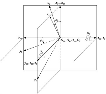
Fig. 2Involute profile of shaper
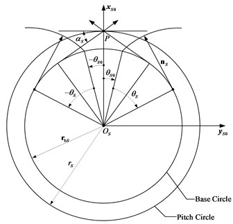
Fig. 2 describes the involute profile of the shaper, and several parameters of the shaper can be clearly expressed in it.
In coordinate system , the vector function of the shaper tooth surface is represented as follows:
where and are the parameters of the shaper tooth surface. is the base circle radius of the shaper. The parameter determines the width of the shaper space on the base circle and can be solved by the equation . Here, is the pressure angle of the shaper.
The tooth surface of the face gear can be represented as follows:
where and are the parameters of the face gear tooth surface. Also, , .
3. Meshing model and tooth contact analysis
Gear sets are important machine elements for power transmissions. Assembly errors which affect the gear transmission performance are a main factor [12]. They include the errors of mounting position deviation and axial misalignment. In this paper, the influence of assembly errors on face gear transmission performance is investigated.
3.1. Meshing model of face gear
To investigate the meshing of the face gear pair with the assembly errors, auxiliary coordinate systems , , and have been set up to simulate the assembly errors of the face gear as shown in Fig. 3. The origin of the coordinate system has an offset deviation from the origin of the coordinate system . Numerical variables, including , , and respectively be along the axes , , and , are the offset errors of the face gear. However, the symbol can be ignored based on the generation principle of face gear. In other words, can be defined as 0. The simulation of horizontal axial misalignment of the face gear can be achieved in the coordinate system , which is established by rotating the coordinate system about the axis through a misaligned angle . Similarly, the coordinate system can be established by rotating the coordinate system about the axis through a misaligned angle . The symbols , , and mentioned above represent the center offset error. and indicate the horizontal and the vertical axial misaligned angles of the gear set, respectively. Therefore, the coordinate system is the reference coordinate system for the face gear coordinate when assembly errors exist.
There is instantaneous line contact between the tooth surface of the shaper and the face gear in the process for generation of the face gear. However, it is sensitive to the assembly errors if the pinion meshing with the face gear is identical with the shaper. Hence, the bearing contact must be localized and instantaneous point contact between the tooth surfaces of the pinion and the face gear can be realized, and this will be achieved if the tooth number of the shaper is more than that of the pinion . Usually, is chosen to be 2 or 3 [1].
Fig. 3Assembly errors of the face gear
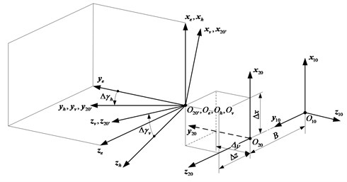
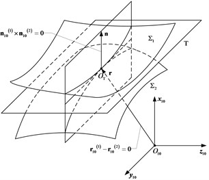
Fig. 4Schematic diagram of tooth tangen
3.2. Tooth contact analysis
When attaining the meshing path and the transmission error of the face gear pair by the tooth contact analysis method (TCA), the position and the unit normal vectors of both the pinion and the face gear tooth surfaces should be represented in the same coordinate system, say , a fixed coordinate system on pinion [13]. The position vectors of the pinion and the face gear tooth surfaces should be the same at the contact point. Besides, their unit normal vectors should be collinear to each other. These can be illustrated in Fig. 4. That is, the following conditions must be satisfied:
and
In Eq. (3), and can be achieved by applying the following equations:
and
where:
where and are the position vectors, while and represent the unit normal vectors of and , described in coordinate system , respectively. Since , Eqs. (3) and (4) form a system of five independent non-linear equations with six independent parameters , , , , , and , where and are the parameters of the pinion tooth surface, while is the rotational angle of the pinion in coordinate system , is the rotational angle of the face gear in coordinate system . By choosing the pinion rotational angle as an input variable, all other parameters can be solved in terms of . The instantaneous contact points on the face gear can be obtained by substituting the solved parameters into the face gear tooth surface equation.
Gear transmission error is expressed as a linear deviation calculated at successive positions of the pinion as it goes through the meshing cycle [14]. The transmission error of the face gear pair can be solved by applying the following equation:
where is the initial rotational angle of the pinion. is the initial rotational angle of the face gear corresponding to . If is defined as 0, will be equal to . It is the equivalent of . That is, can be simplified as the following equation:
4. Numerical examples
Based on the mathematical model and the meshing model of the face gear sets, the gear tooth profiles can be plotted, and computer simulations of the face gear sets can be performed. Table 1 lists some major design parameters of the shaper, pinion, and face gear.
The mating model of the face gear pair defined by the geometrical parameters given in Table 1 is created as shown in Fig. 5.
Fig. 5Meshing model of the gear pair
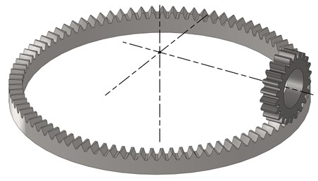
Table 1Major design parameters of the shaper, pinion, and face gear
Parameters | Shaper | Pinion | Face gear |
Number of teeth | 25 | 22 | 89 |
Module [mm] | 3 | 3 | – |
Pressure angle [°] | 20 | 20 | – |
Addendum coefficient | 1 | 1 | – |
Tip clearance coefficient | 0.25 | 0.25 | – |
Axis shaft angle [°] | – | 90 | 90 |
Width [mm] | 15 | 17 | 13 |
Inner radius of undercutting [mm] | – | – | 130.061 |
Outer radius of pointing [mm] | – | – | 144.489 |
Inner radius [mm] | – | – | 131 |
Outer radius [mm] | – | – | 144 |
Poisson’s ratio | – | 0.3 | 0.3 |
Elastic modulus [GPa] | – | 210 | 210 |
4.1. Misalignment sensitivity analysis
In numerical TCA solution, the influence of the assembly errors in the mating gear members on the contact path and transmission error (TE) is investigated for the unloaded condition. In order to investigate the misalignment sensitivity on the face gear pair, errors are studied independently without coupling, and examples of contact path distribution under various conditions of gear meshing are listed in Table 2. The coefficient of restitution and the coefficient of friction of all cases are assumed to be 0 in the study. The case 1 represents the contact path distribution under ideal assembly condition.
Table 2The kinds of assembly errors
Case 1 | 0 | 0 | 0 | 0 | 0 |
Case 2 | ±0.4, ±0.2 mm | 0 | 0 | 0 | 0 |
Case 3 | 0 | 0 | ±0.11 mm | 0 | 0 |
Case 4 | 0 | 0 | 0 | ±0.045° | 0 |
Case 5 | 0 | 0 | 0 | 0 | ±4.5° |
4.1.1. Contact path
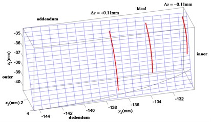
The contact paths aroused by case 1 and case 2 are shown in Fig. 6. The ideal contact paths shown in case 1 are located in the centre-inner region of the face gear tooth flank when the misalignments do not exist. It can be illustrated that the position of the contact path moves from the middle of the tooth flank (ideal region) to the inner or outer radius as the offset error increases. The effect of positive is to make the contact points more close to the inner radius and the addendum of the face gear tooth surface. It results in a small torque driving on the gear sets and a more bending for the face gear. The negative offset error has opposite effect on contact path and force condition. When the gear offset of is equal to +0.4 mm, the theoretical contact path almost moves out of the face gear tooth flank. As shown in Fig. 7, influence of the face gear offset error on contact path can be investigated. The positive which is equal to +0.11 mm moves the contact path towards the outer radius and the dedendum of the face gear tooth surface. It leads to a large torque driving upon the gear sets and a large capacity for the face gear. But the effect of negative has opposite effect on the influence to that of positive . The contact path almost moves out of the tooth flank when the offset error is equal to –0.11 mm, similar to the tendency obtained in Fig. 6. From the above two sets of results, it is explicit that the contact path is more sensitive to the offset error than the offset error .
Fig. 6Influence of the face gear offset error Δx on contact path
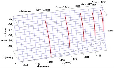
Fig. 7Influence of the face gear offset error Δz on contact path
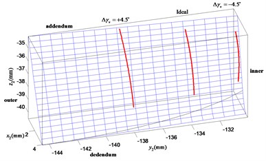
The contact path distribution with angular misalignment along the horizontal direction can be represented in Fig. 8. The positive which is equal to +0.045° moves the contact path towards the inner radius and the addendum of the face gear tooth surface. It causes a smaller torque driving on the gear sets and a more bending for the face gear. The negative has opposite effect on the influence to that of positive . Fig. 9 shows the contact path distribution when the angular misalignment of gear axes in the vertical plane occurs. The effect of negative is to make the contact points more close to the inner radius and the dedendum of the face gear tooth surface. It results in a smaller torque driving on the gear sets and a lager load capacity for the face gear. The effect of positive has opposite effect on the influence to that of negative . The contact path almost moves out of the tooth flank when the angular misalignment error is equal to –4.5°, similar to the tendency studied in Fig. 8. Thus, from these two sets of results, it is obvious that the contact path is more sensitive to the horizontal axial error than the vertical axial error .
Fig. 8Influence of the horizontal axial misalignment error Δγh on contact path
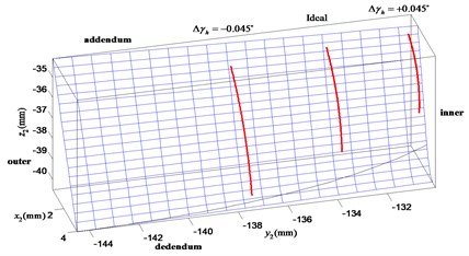
Fig. 9Influence of the vertical axial misalignment error Δγv on contact path
Overall, in any case when the errors are large enough, the meshing pinion and face gear pair cannot engage well with each other.
4.1.2. Transmission error
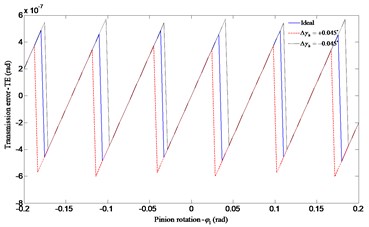
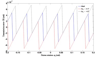
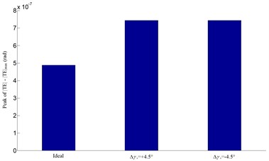
The influences of misalignments of the meshing gears on predicted transmission error are represented in Figs. 10-13. As the assembly errors exist, the theoretical angular is in jagged shape. In this gear meshing, the pinion and the face gear will contact at rotational angle of pinion , from –0.2 to 0.2 rad (a complete mesh cycle). Both the positive and the negative assembly errors cause a little larger peak value of than the ideal one does. From the four sets of results in Figs. 10-13, the four errors only have modest effect on transmission error, but the angular misalignment in the horizontal plane causes the lowest peak value of with a similar contact path which almost moves out of the face gear tooth flank.
Fig. 10Influence of the face gear offset error Δx on transmission error
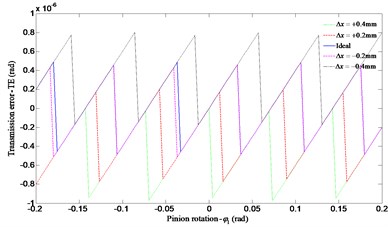
a) Transmission error
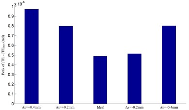
b) Peak of
Fig. 11Influence of the face gear offset error Δz on transmission error
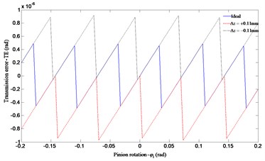
a) Transmission error
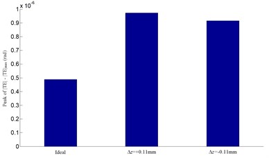
b) Peak of
Fig. 12Influence of the horizontal axial misalignment error Δγh on transmission error
a) Transmission error
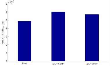
b) Peak of
Fig. 13Influence of the vertical axial misalignment error Δγv on transmission error
a) Transmission error
b) Peak of
4.2. Loaded tooth contact analysis
Considering the necessary and importance of the FEM for the computation of deformations, a finite element-analytical mechanics approach is applied to simulate the physics of tooth engagement [9]. Additional acknowledge about the theoretical basis can be found in the work published by Vijayakar [15]. Then, the LTCA is used to study the stick-slip trajectories on the gear surfaces. Fig. 14 shows an FEM model of the gear pairs that were composed of 37 200 (pinion) and 34 600 (face gear) hexahedral elements with eight nodes.
Fig. 14Finite element model of five pairs of teeth
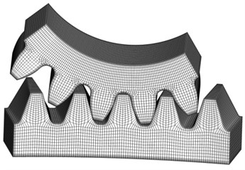
Fig. 15Finite load sharing for the spur pinion at different torques
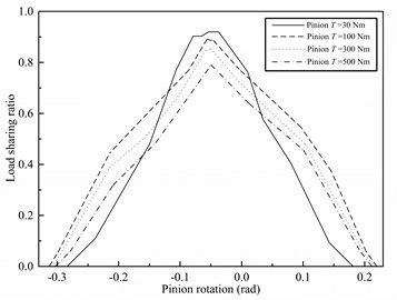
The calculated load sharing values for the spur pinion for the four different torque levels (30, 100, 300, 500 Nm) is shown in Fig. 15. The four load sharing diagrams have a similar trend. But under very light torque load (30 Nm), the load sharing diagram compares well with the theoretical one. Moreover, the amplitude of the load sharing ratio increases with the decrease of the torque. It matches up with the change rule of the contact ratio.
Under very light torque level (30 Nm), the contact pattern (ellipse) is near the contact path resulting from the theoretical tooth contact analysis for the unloaded condition as investigated earlier, this can be shown in Fig. 16. Then, Fig. 17 shows that the contact patterns of the face gears resulted from the different torque levels. For larger torque levels of more than 100 Nm, the face gear pairs show line contact. The area of the contact grows larger with the increase of the torque levels from 100 Nm to 500 Nm. This is caused by the tooth elastic deformation.
Fig. 16Contact patterns for torque load (30 Nm) for face gear

a) Meshing position 1
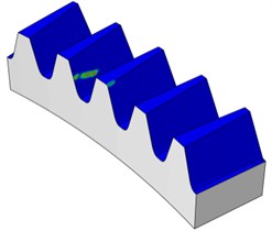
b) Meshing position 2
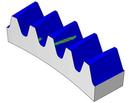
c) Meshing position 3
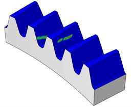
d) Meshing position 4
Fig. 17Contact patterns for different torque levels (100, 300, 500 Nm) for face gear
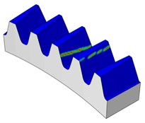
a) Pinion 100 Nm

b) Pinion 300 Nm
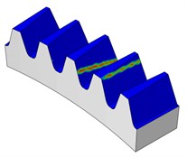
c) Pinion 500 Nm
5. Conclusions
Based on the mathematical model of the face gear, the transmission error of the gear pair under various assembly errors are investigated by applying the TCA method. Besides, the load distribution and the contact patterns of the gear set under ideal assembly condition are also investigated by using the developed computer simulation programs. Several illustrative numerical examples are presented as well. According to the numerical results, the following conclusions can be drawn.
1) All assembly errors considered in this study tend to worsen the contact path, but only have modest effect on transmission error. Both the contact path and the theoretical are more sensitive to the offset error than the offset error for offset deviations, and also more sensitive to the horizontal axial misalignment error than the vertical axial misalignment error for axial misalignments. Further, among the four assembly errors studied, the angular misalignment in the horizontal plane causes the lowest peak value of with a similar contact path which almost moves out of the face gear tooth flank.
2) The effect of positive results in a small torque driving on the gear sets but a more bending for the face gear. The effect of negative or positive shows the same behavior. However, the effect of negative leads to a smaller torque driving upon the gear sets and a lager load capacity for the face gear.
3) Based on the FEM, the amplitude of the load sharing ratio increases with the decrease of the torque. Also, the contact pattern compares well with the contact path resulting from the theoretical tooth contact analysis (unloaded condition) under light torque level. But for a larger torque load, the pinion and the face gear meshes with each other as line contact because of the tooth elastic deformation.
References
-
LitvinF. L. Gear geometry and applied theory. Second Edition, Cambridge University Press, New York, 2004, p. 508-546.
-
Litvin F. L., Fuentes A., Howkins M. Design, generation and TCA of new type of asymmetric face-gear drive with modified geometry. Computer Methods in Applied Mechanics and Engineering, Vol. 190, Issue 43, 2001, p. 5837-5865.
-
Litvin F. L., Fuentes A., Zanzi C., Pontiggia M. Design, generation, and stress analysis of two versions of geometry of face-gear drives. Mechanism and Machine Theory, Vol. 37, Issue 10, 2002, p. 1179-1211.
-
Litvin F. L., Gonzalez-Perez I. I., Fuentes A., et al. Design, generation and stress analysis of face-gear drive with helical pinion. Computer Methods in Applied Mechanics and Engineering, Vol. 194, Issue 36, 2005, p. 3870-3901.
-
Chang S.-H., Chung T.-D., Lu S.-S. Tooth contact analysis of face-gear drives. International Journal of Mechanical Sciences, Vol. 42, Issue 3, 2000, p. 487-502.
-
Chung T.-D., Chang Y.-Y. An investigation of contact path and kinematic error of face-gear drives. Journal of Marine Science and Technology, Vol. 13, Issue 2, 2005, p. 97-104.
-
Zeng Y., Zhu R., Lu W. Computerized simulation of meshing in perpendicular face-gear drive. Journal of Nanjing University of Aeronautics & Astronautics, Vol. 31, Issue 6, 1999, p. 644-649.
-
Li Z., Zhu R. Load tooth contact analysis on face gear driver. Journal of Nanjing University of Aeronautics & Astronautics, Vol. 42, Issue 2, 2010, p. 219-223.
-
Barone S., Borgianni L., Forte P. Evaluation of the effect of misalignment and profile modification in face gear drive by a finite element meshing simulation. Journal of Mechanical Design, Vol. 126, Issue 5, 2004, p. 916-924.
-
Tang J., Ping Y. Loaded meshing simulation of face-gear drive with spur involute pinion based on finite element analysis. Journal of Mechanical Engineering, Vol. 48, Issue 5, 2012, p. 124-130.
-
Guingand M., De Vaujany J.-P., JacquinC.-Y. Quasi-static analysis of a face gear under torque. Computer Methods in Applied Mechanics and Engineering, Vol. 194, Issue 39, 2005, p. 4301-4318.
-
Zhu C., Song C., Lim T.C., Peng T. Pitch cone design and influence of misalignments on tooth contact behaviors of crossed beveloid gears. Mechanism and Machine Theory, Vol. 59, 2013, p. 48-64.
-
Chao L.-C., Tsay C.-B. Contact characteristics of spherical gears. Mechanism and Machine Theory, Vol. 43, Issue 10, 2008, p. 1317-1331.
-
Sunghoon Oh. S., Sewoong Oh., et al. A study on modeling and optimization of tooth microgeometry for a helical gear pair. International Journal of Precision Engineering and Manufacturing, Vol. 14, Issue 3, 2013, p. 423-427.
-
Vijayakar S. M. Finite element methods for quasi-prismatic bodies with application to gears. Ph. D. Dissertation, Ohio State University, Columbus, Ohio, 1987.
About this article

The authors are grateful to the National Science Foundation of the PRC for the grant. Part of this work was performed under Contract No. 51075408.
