Abstract
How to define the clearance between rope-guided conveyances and shaft wall reasonably has confused peers for more than one hundred years. In this paper, the fluid-structure interaction approach was used to simulate the lateral oscillations of rope-guided conveyances. With Yaoqiao vertical production shaft taken into account to validate this approach, user-defined functions coupled with ANSYS FLUENT were employed to conduct the two-dimensional numerical simulation, and the simulation results show that the lateral aerodynamic buffeting force when two conveyances pass each other is much larger than Coriolis force. What’s more important, with the lateral acceleration, velocity and displacement of the conveyances obtained, the simulation results can explain how the lateral aerodynamic buffeting force to oscillate the conveyance laterally successfully. This approach can be easily extended to three-dimensional simulations, to be more reasonable.
1. Introduction
With a number of advantages, such as short installation time, lower capital costs, lower maintenance requirements and smooth travel, more and more rope guides have been used all over the world, especially in short life mines with relatively shallow shafts [1, 2]. But how to define the clearance between conveyances and shaft wall reasonably has confused peers for more than one hundred years. In a considerable long time, the reasons why the conveyance moves laterally are unknown, and the design of rope guide was commonly based on what are appropriately described as “industry rules of thumb”, which have evolved from experience in existing reasonably shallow shafts [2, 3].
In order to figure out why the conveyance moves laterally, many researchers have done enormous work. Their work can be classified into four aspects including field performance tests [4-8], scale model tests [9, 10], theoretical analysis [2, 11] and computational fluid dynamics (CFD) [3, 12]. Earlier, Belyi thought that the Coriolis force during the conveyance travelling in the shaft as a result of the rotation of the earth was the main source of excitation which generated lateral oscillations and he derived a formula to calculate the clearance between conveyances [4]. With the development of laser-based oscillation-measuring instrument, Chen [5, 6] took hundreds of measurements in more than ten mines equipped with rope guides. However, Chen found that the Coriolis force was not the main source of excitation and Belyi’s calculation formula was deficient [5, 6]. By using onboard strapdown inertial navigation system (INS) to record skip position and attitude successfully, Buchinski found that hoisting speed, balance rope torque, Coriolis force, and position of guide ropes all have a profound effect on a skip’s lateral stability during flight [7]. Based on the physical similarity and dimensional analysis, scale models of mine shaft rope-guide system were thought to possess the same dynamic properties as the full-scale counterparts [9]. Hurlin [10] successfully measured the aerodynamic buffeting forces and moments between passing mine cages on a 1:33 dynamic scale model of the shaft. Van Der Lingen [11] established the differential equations of motion for the rope-guided conveyance, and the result indicates that pitching motion of the conveyance is unimportant. With the empirical formula to calculate the aerodynamic forces, Greenway et al. [2] developed a three degree of freedom model of conveyance and solved this model by MATLAB numerically.
With the development of CFD, numeric experiment has become a powerful tool to investigate the mine shaft rope-guide system. With the help of CFD, Hamilton [12] predicted the aerodynamic loads on conveyances. Based on numerous CFD analyses, Krige [3] established the aerodynamic coefficients for specific cases and developed the guidelines for the design of rope guides finally. Although many studies have been published concerning the later oscillations of rope-guided conveyance, how the lateral aerodynamic buffeting force to oscillate the conveyance laterally hasn’t been reported. In this study, fluid-structure interaction (FSI) method was used to reveal these details.
2. Methodology
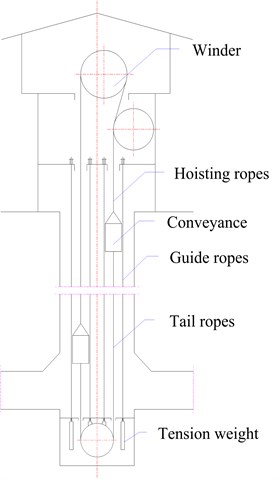
The sketch of rope guide friction hoisting system is shown in Fig. 1. The longitudinal motion of the conveyances and ventilation induce the motion of air and the aerodynamic force, especially when the conveyances pass each other. Then the lateral aerodynamic forces cause the lateral motion of conveyances, and in reverse, the lateral motion of conveyances also change the air flow. So the lateral motion of conveyances interacts with the air flow.
The computational demands of three-dimensional (3D) FSI simulation is very high, so two-dimensional (2D) FSI simulation is adopted in this study according to the same ratio between the cross sectional area of conveyance and that of shaft. In order to establish the mathematical model, it is assumed that the centre of gravity of the conveyance is exactly below the point at which the hoisting ropes are attached to the conveyance. Generally, for multi-rope hoisting systems, opposite handed pairs of ropes are used as hoisting ropes and non-rotating ropes are used as tail ropes to limit the torque applied to the conveyance. So the rotation of the conveyance about a vertical axis is neglected in 2D simulation for multi-rope hoisting systems.
Fig. 1Sketch of rope guide friction hoisting system
2.1. Equations of lateral motion for the conveyance
Generally, the conveyances are made up of structure steel, and the deformation displacement caused by aerodynamic force is much smaller than the lateral motion displacement. So the conveyances are treated as rigid bodies travelling on the guide ropes. The lateral loads on the conveyances vary with the longitudinal velocity and the vertical position.
Equations governing the behaviour of a conveyance travelling on rope guides have been derived previously by a number of authors [1, 2, 11]. However, FSI method hasn’t been reported to simulate the lateral motion of the conveyance.
According to measurements [7, 8], the rotation of the conveyance about the horizon axis is very small, so this degree of freedom is omitted in this study, which is consistent with the reference 2 and reference 3. The equation of lateral motion for the conveyance can be represented as follows:
where is the mass of conveyance, is the displacement, is the lateral equivalent spring stiffness, and is the disturbing forces which mainly consist of lateral aerodynamic forces and Coriolis force [2, 3].
The lateral equivalent spring stiffness of rope-guided conveyance has nonlinear forms [1, 4, 13] and a linear form [3]. The linear form can be represented as follows [3]:
where is the number of rope guides guiding a single conveyance, is the rope guide tension at conveyance elevation in the shaft, is the overall length of the rope guides, is the rope guide length between the top of conveyance and the top anchor point, is the rope guide length between the bottom of conveyance and the bottom anchor point, is the number of hoisting ropes for a single conveyance, is the hoisting rope tension at conveyance, is the number of tail ropes for a single conveyance, and is the tail rope tension at conveyance.
2.2. Governing equations of air flow
With respect to dynamic meshes, the integral form of the conservation equation for a general scalar, on an arbitrary control volume, whose boundary is moving can be written as follows [14]:
where is the fluid density, is the flow velocity vector, is the mesh velocity of the moving mesh, is the diffusion coefficient, and is the source term of . Here, is used to represent the boundary of the control volume, .
To construct the mass conservation equation, the momentum equation and the energy equation, the relevant entries for and their rates of change per unit volume as defined in Eq. (3) are given in Table 1.
Table 1The relevant entries for ϕ
Mass conservation equation | 1 | 0 | 0 |
Momentum equation | |||
Energy equation |
2.3. Numeric simulation flowchart
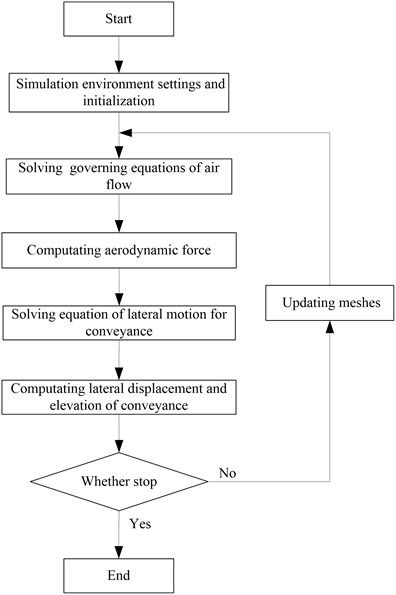
The detailed flowchart of FSI simulation for the rope guide hoisting system is given in Fig. 2.
Fig. 2Flowchart of FSI simulation for the rope guide system
3. Application
This simulation technique was used to assess the performance of the rope guide system installed in Yaoqiao vertical production shaft, which equipped with two rope-guided skips.
3.1. Main shaft parameters
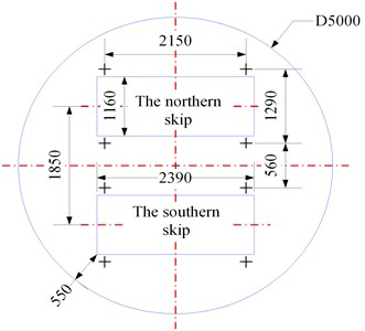
Shaft plan profiles are provided in Fig. 3, and Table 2 gives the main shaft parameters. The Coriolis force always acts in a westerly direction for an ascending conveyance and in an easterly direction for a descending conveyance, so the Coriolis force couldn’t induce the conveyance to move north or south directly, and then the Coriolis force is neglected in this 2D simulation. Furthermore, it is assumed that the conveyances have no lateral displacement or lateral velocity when they are at the beginning of the simulation.
Table 2The main shaft parameters of Yaoqiao production shaft
Hoisting ropes | 6 off, 28 mm, 2.62 kg/m |
Tail ropes | 2 off, 40 mm, 6.696 kg/m |
Guide ropes | 4 off per skip, 40.5 mm, 8.94 kg/m |
Skip mass | 15 t |
Hoisting distance | 320 m |
Hoisting speed | 9.7 m/s |
Payload | 9 t |
Shaft diameter | 5 m |
Method of tensioning | Weight |
Tension load indicated | 5650 kg per guide rope |
Design ventilation | Approx. 368 m3/min, downcast (0.312 m/s) |
Nominal clearances | 550 mm skip to wall, 560 mm skip to skip |
Fig. 3Skip plan profiles
3.2. User-defined function coupled with ANSYS FLUENT
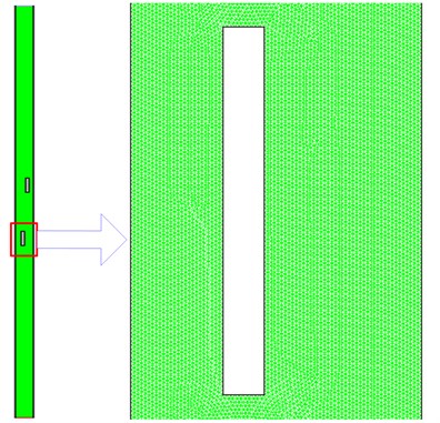
The transport equations were solved by ANSYS FLUENT with PISO scheme, and user-defined function (UDF) was programmed by C language to define the longitudinal motion and solve the equations of lateral motion for the conveyances with the modified Euler method. The Reynolds number is about 3.4×10⁶, far larger than 2300, so the airflow in shaft is turbulent. The shear-stress transport (SST) - model was adopted to simulate the turbulent airflow, and the detailed theory can be found in reference 15. The displacements of conveyance have been implemented using a dynamic mesh with the remeshing algorithm in ANSYS FLUENT. Fig. 4 illustrates the unstructured mesh and the total number of control volumes is around 4×10⁵. The time step size was set to 0.002 seconds in order to get enough time resolution for the dynamic analysis. The total simulation time is 14 seconds for the travelling conveyances, and a total number of 7000 time steps, with approximately 30 iterations for each time step, were necessary to resolve each case.
Fig. 4Mesh used for calculations
3.3. Results
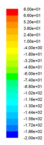
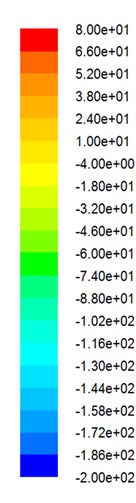
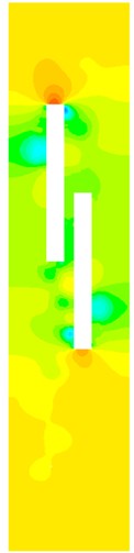
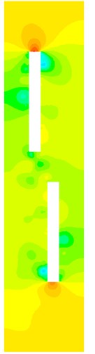
Before and after two skips pass each other, the series of pressure contours are shown in Fig. 5. Here, denotes the distance between the two centers of gravity of skips.
Fig. 5Pressure contours

a) 6.79 m

b) 4.85 m

c) 2.91 m

d) 0.97 m

e) –0.97 m
f) –2.91 m

g) –4.85 m
h) –6.79 m
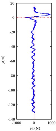
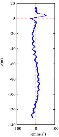
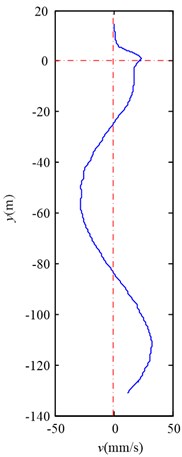
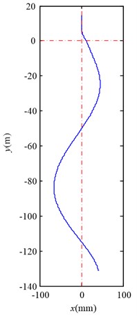
Fig. 6 shows the lateral aerodynamic force, lateral acceleration, velocity and displacement of the southern full skip during travelling upward, and Fig. 7 shows the lateral aerodynamic force, lateral acceleration, velocity and displacement of the northern empty skip during travelling downward. Here, denotes the distance between the center of gravity of skip and the cross point.
Fig. 6Simulation results for the southern full skip during travelling upward
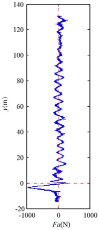
a) Lateral aerodynamic force
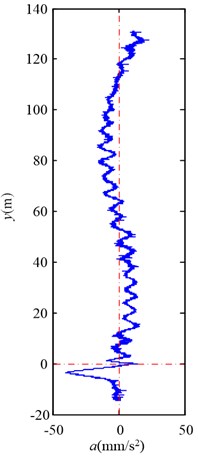
b) Lateral acceleration
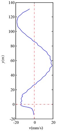
c) Lateral velocity
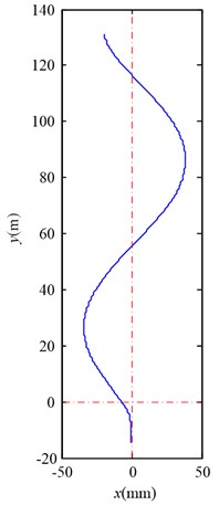
d) Lateral displacement
Fig. 7Simulation results for the northern empty skip during travelling downward
a) Lateral aerodynamic force
b) Lateral acceleration
c) Lateral velocity
d) Lateral displacement
3.4. Discussion
As Fig. 5 shows, the pressure contours change quickly when two skips pass each other. When two skips are far away, the pressure at upwind surface of skips are larger than other surface. When two skips pass each other, the negative pressure zones grow at the sides of two skips.
As Fig. 6(a) and Fig. 7(a) exhibit, there is a considerable lateral aerodynamic buffeting force when two conveyances pass each other, and the maximum lateral aerodynamic force is about 960 N. As the air flow is turbulent, the lateral aerodynamic force is still oscillating after two conveyances pass each other, but the amplitude becomes much small, about 200 N. And the trend is in accordance with the Hurlin’s measurement on a scale model [10]. In this case, the maximum Coriolis force is about 21.5 N, so the lateral aerodynamic force is mach lager than the Coriolis force.
As Fig. 6 and Fig. 7 illustrate, the lateral aerodynamic buffeting force gives the conveyance a lateral impact acceleration, and then the conveyance begins to oscillate laterally. Moreover the tendency of motion for conveyance is in agreement with the Chen’s measurement on Yaoqiao vertical production shaft [6]. The full skip oscillates from about –34.2 mm to +38.5 mm during travelling upward, and the empty skip oscillates from about +45.1 mm to –65.5 mm during travelling downward. The maximum skip deflection near the wall is less than the opposite direction. The simulation compared with Chen’s measurement is given in Table 3. As this article aims to reveal the details how the lateral aerodynamic force acts on conveyance, some other factors, such as initial rope guide motion and external displacement [3], are ignored, and maximum skip deflection is less than Chen’s measurement [5].
Table 3The simulation compared with Chen’s measurement [5]
Maximum skip deflection during skip travelling upward | Maximum skip deflection during skip travelling downward | ||
Our simulation | Chen’s measurement | Our simulation | Chen’s measurement |
72.7 mm | 66-125 mm | 110.6 mm | 134-150 mm |
4. Conclusions
This paper presents a numerical methodology based on fluid-structure interaction technique to properly simulate the lateral oscillations of rope-guided conveyances. Although cases of two-dimensional flow are studied in the present work, an extension to three-dimensional problems of this method can be expected. The fluid-structure interaction method is a technically sound approach to predicting the behaviour of rope-guided hoisting systems, and can provide the designer with the ability to calculate the lateral oscillations of rope-guided conveyances in a consistent manner.
References
-
Slonina W., Stuhler W. Safety problems posed by rope shaft guides. Research Report, Commission of the European Communities, Mines Safety and Health Commission, Luxembourg, 1980.
-
Greenway M. E., Jujnovich B. A., Grobler S. R., Baroni N. P. Behaviour of rope-guided conveyances. Proceedings of Mine Hoisting 2000, Fifth International Conference, SAIMM Symposium Series S25, Johannesburg, South African, 2000, p. 89-98.
-
Krige G. J. Guidelines for the design of rope guides. International Conference on Hoisting and Haulage, Perth, Australia, 2005, p. 275-283.
-
Belyi V. D. Rope guides in shaft hoisting installations. Moscow Ugletekhizdat, Moscow, 1959, (in Russian).
-
Chen X. Analysis of the Soviet calculation formula for the clearance between rope-guided conveyance to conveyance. Design of Coal Mine, Vol. 26, Issue 4, 1979, p. 17-23, (in Chinese).
-
Chen X. Swing of hoisting conveyance using steel rope guides. Coal Science and Technology, Vol. 13, Issue 2, 1985, p. 23-26, (in Chinese).
-
Buchinski K. W. Skip rotation: a collision course or controllable motion. 11th CIM Underground Operators Conference, Saskatoon, Canada, 1993.
-
Shatalov M., Tromp H., Lombard P. Motion of rope-guided mining conveyances, measured by inertial measurement unit. Proceedings of Mine Hoisting, Fifth International Conference, SAIMM Symposium Series S25, Johannesburg, South African, 2000, p. 79-82.
-
Van Der Elst W. J. Dynamic scale model testing of rope guide installations for mine shafts. The South African Mechanical Engineer, Vol. 11, Issue 11, 1961, p. 234-257.
-
Hurlin R. The aerodynamic buffeting force between passing mine cages. Ph. D. thesis, University of the Witwatersrand, 1993.
-
Van Der Lingen T. W. Dynamic behaviour of rope-guided conveyances with reference to scale model testing. The South African Mechanical Engineer, Vol. 11, Issue 12, 1961, p. 163-185.
-
Hamilton R. Rope-guided hoisting for 2000 and beyond – engineering rope guides for deep shafts. Proceedings of Mine Hoisting, Fifth International Conference, SAIMM Symposium Series S25, Johannesburg, South African, 2000, p. 83-88.
-
Greenway M. E. Lateral stiffness and deflection of vertical ropes with application to mine shaft hoisting. Australian Journal of Mechanical Engineering, Vol. 5, Issue 1, 2008, p. 59-70.
-
ANSYS Inc. Ansys fluent theory guide. ANSYS Inc, 2011.
-
Menter F. R. Two-equation eddy-viscosity turbulence models for engineering applications. AIAA Journal, Vol. 32, Issue 8, 1994, p. 1598-1605.
About this article

This work is financially supported by the Fundamental Research Funds for the Central Universities (Grant No. 2012LWB34), Program for Changjiang Scholars and Innovative Research Team in University (Grant No. IRT1292) and the Project Funded by the Priority Academic Program Development of Jiangsu Higher Education Institutions (PAPD).
We are grateful to the Advanced Analysis and Computation Center of CUMT for the award of CPU hours to accomplish this work.
