Abstract
In order to obtain the satisfied machining requirements, ball-screw feed drive systems of machine tools need to work accurately and efficiently. A new method which can predict exactly the dynamic performance of feed drive systems by integrating the virtual prototype and finite element is proposed in this paper. The influences of flexible bodies and joint surfaces on dynamic performance were studied based on the finite element theory and dynamic theory. The exciting vibration simulation model can then be formed by using the integration method. The frequency response curves of ball-screw feed drive systems were obtained based on the vibration model, which matched quite well with the experimental results, where the stiffness and damping ratio were also identified respectively. It can be concluded that, therefore, the proposed integration simulation method can offer a theoretical foundation and reference for dynamic optimal design for other products.
1. Introduction
Producing parts correctly using the shortest time and the lowest cost (i.e., the most cost-effective way) has always been the goal of manufacturing technologies. The product complexities, however, have been increasing and the competitive product life cycle times have been reduced. These have impeded the quick realization and testing of physical prototypes before successful and economical mass-production. Virtual prototype (VP) and finite element (FE) methods are cost-effective ways to test designed parts (such as detecting weak spots) and optimize the design before manufacturing. Therefore, instead of prototyping and testing physical parts before mass-production, VP and FE methods are useful and necessary alternative tools.
Efforts have been made to model a design as close as its physical one using VP methods, although it is difficult. Altintas et al. [3] have presented FE analysis of machine tools, coupled simulation of structural dynamics and control loops of machine tools in a macroscopic view. Varanasi [4] has modeled the ball screw using beam formulations, which captured the axial and torsional dynamics of the ball-screw drive. However, the lateral deformations of the ball screw were not taken into account in these two models, which may affect the positioning accuracy and performance of the machine tool. Zhu [5] has researched the modeling of a parallel robot with flexible multi-body system and dynamic simulation. Zaehet al. [6-7] has researched the simulation of machining performance by integrating the finite element method and multi-body simulation of machine tools. They have compared the cutting forces of both the simulation and the experiments. But the model used for the screw-nut interface stiffness matrix is not good enough to capture the coupling between the axial, torsional, and lateral dynamics of ball screw drives, although the lateral deformations of the ball screw were taken into consideration. Chinedum and Altintas [8-9] have proposed a screw-nut interface model including the effect of lateral vibrations. The presented model can help predict the coupling between axial and lateral dynamics of ball screw drives. The effect of this dynamic coupling on the positioning accuracy of the drive were also presented with experimental validations.
A proposed model providing a more realistic platform for designers is presented in this paper to optimize the drive parameters for machine tool applications. By integrating VP and FE methods on rigid-flexible coupling systems, simulation results of excitation performance can be easily obtained, thus enabling precise prediction of the dynamic performance of ball-screw feed drive systems. The remainder contents of this paper starts with a briefly description of the components of a typical ball screw drive systems and its dynamic model in Section 2. Following this, a detailed study of the integration of VP and FE method is given in Section 3, where the influence of flexible multi-bodies and joint interface are included. Then, comparison between the proposed model and experimental results is presented in Section 4. Finally, in Section 5, some major conclusions can be seen.
2. General structural of ball-screw feed drive systems
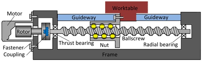
Understanding the dynamic performances of ball-screw feed drive systems of machine tools is important as it will help make those machine tools work accurately and efficiently. A typical ball-screw drive system, with some major mechanical structure components, can be seen in Fig. 1. One main component is the ball-screw which is attached to the rotor through coupling and supported by the thrust bearing and radial bearing at both ends. Thrust bearing constrains the ball-screw drive system axially and radically and radial bearing is axially unconstrained to control thermal expansion of the screw [3, 9]. It can be seen in the figure that the rotary motion from the screw is converted to a translation at the nut through the constrained relative motion of the screw-nut interface, which is a curved surface contact each other under a load. The contact portion incurs elastic deformation, forming a contact surface, on which contact stress is generated. The ball-screw is relative long and slender compared to other components. Another main component is the linear guide-way system which contains balls or cylindrical rollers as rolling elements. Accordingly, the linear system is vertically, horizontally and longitudinally loaded, and thus can guide linearly and support the table vertically. The machine tool provides the supporting structure for all the components in the assembly, such as the table, the frame and the motor.
Fig. 1Mechanical structure components of a ball-screw feed drive systems
3. Modeling of flexible bodies and joint interface
3.1. Integration of VP and FE method
Virtual prototypes of feed drive systems are computer simulation models of the physical products. These simulation models can be presented, analyzed, tested and evaluated like real drive systems. The core parts of VP are rigid multi-body system kinematics, dynamics modeling and corresponding numerical algorithms. VP can help realize large movements and analysis on one system level. Rigid multi-bodies are parts that have mass and inertia properties but cannot deform [2, 10]. Some commercial software, such as ADAMS, DADS, and SIMPACK, are always suitable VP platforms. FE is used to calculate static stiffness or dynamic characteristics of feed drive system. It is especially suitable for analyzing single part such as spindle, columns and slide. ANSYS, NATRAN and ABAQUS are some popular FE software platforms. In order to transfer existing geometry models, both VP and FE based software provide standard formats for 3-dimensional (3D) computer-aided-design models to be imported in. Some popular formats can be Parasolid, IGES, and STEP. The proposed method can be started with some simple static analysis before an analysis of the structural dynamics based on FE theories. Following this, an integration of flexible bodies into rigid multi-body simulation can be conducted. Small linear deformations could be included in the system, with the advantages of both FE and VP methods integrated together, for the simulation of feed drive system [11]. The flexible multi-body simulation can then be used to simulate the dynamic behavior of feed drive system. In order to get the dynamic performance of feed drive system exactly, the correct simulation should be the integration of large machine movements under consideration of small deformations in the structural components by FE and VP methods.
Fig. 2Integration of FE and VP in one system
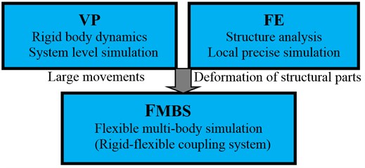
The integration of both FE and VP in a system can be seen in Fig. 2. The FE modeling is used to analyze and gain some theoretical understanding of the structural dynamics of the ball screw drive systems, particularly the complex transmission of motion and vibrations at the screw-nut interfaces. Then the experimental parameter identification is used to obtain a more compact and accurate representation of the dynamics. In the system, the ball-screw is modeled using Timoshenko beam finite elements, while the rotor, table and nut are modeled as lumped masses and inertias. The couplings, bearings, fasteners and guide-ways are modeled using linear and rotary spring elements. As for the frame, it is assumed to be rigid and fixed to the ground as all measurements are conducted relative to it. The interfaces between screw and nut are modeled using a special spring element. A detailed description of this methodology is presented in the following sections.
3.2. Joint interface of the linear guide-way
The linear guide-way system, loaded only vertically, horizontally and longitudinally, contains balls or cylindrical rollers as rolling elements. The constraints of the joint interface model can be seen in Fig. 3. There are five degrees of freedom (DOF) constraints to support external loads. The forces and torques are analyzed based on the vibrated model, with those mentioned constraints.
Equilibrium equations of static force based on equivalent principle can be expressed as follows:
where and are the stiffness in and direction respectively; , and are the rotational stiffness in , and direction respectively; and are the displacements of external loads; is the torque; and is the torque angle.
Fig. 3Vibrated model and constraints of linear guide-way
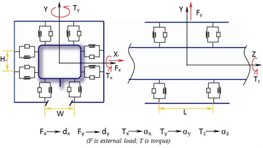
Linear guide-way is typically modeled as linear springs in the vertical and lateral directions. The typical linear guide unit consists of a slide and rail assembled together. Depending on the interface between the slide and rail, the linear guide-ways can be categorized as either hydrostatic or friction guide-ways. The stiffness constants for the springs are usually provided in manufacturers’ catalogs (SNS 35 LRG). They are regarded as functions of preload forces for the friction and hydrostatic guides, respectively.
3.3. Joint interface of the screw-nut
The screw-nut interface of the drive system is of very importance because the rotary motion and torques from the ball-screw are converted to linear motion and thrust and transmitted to the table. Since the screw is modeled as a beam element and the nut as a lumped mass, all the springs distributed around the screw at the screw-nut interface region should not be ignored. The contact section within the interface region translates and rotates about the center point as a rigid body. The displacement and rotation vectors from the center point to each spring are defined in different directions. Obviously, each ball in the screw-nut interface has a unique local-global transformation matrix which depends on its contact configuration. The ball stiffness matrices distributed all around the contact interface can be connected to the nodes of the nut and balls crew. The stiffness appears on the leading diagonal.
Fig. 4Preload mechanisms and joint interface of screw-nut
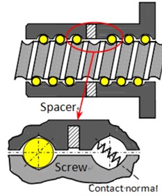
a) Spacer preload
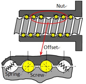
b) Offset preload
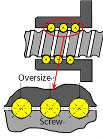
c) Oversize preload
There are off-diagonal terms which couple the torsional direction to the axial direction, as shown in Fig. 4. The rotary motion can be transmitted to the nut as linear motion. In the spacer preload mechanism, a spacer is inserted between two nuts in order to apply a preload. By varying the thickness of the spacer, the preload applied to the interface can be conveniently adjusted, as shown in Fig. 4(a). In the offset preload, one nut is used instead of two nuts. The lead is increased by a small amount in the middle portion of the nut to achieve the same preloading effect as the spacer, as shown in Fig. 4(b). In the oversize preload, the balls are a little larger in size than the grooves, thus creating a preload force, as shown in Fig. 4(c).
During modeling the screw-nut interface, the mass of the balls is assumed to be negligible, while all the compliances are assumed to come from their points of contacts with the screw and nut. Therefore, the balls can be modeled as massless springs having a stiffness ball aligned along the common line of contact (contact normal) between screw and nut [9].
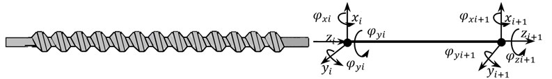
3.4. Modeling of the leading screw
Since ball-screw is a simple geometry, it can be readily modeled using beam finite elements. The 3D geometry and Timoshenko beam element can be seen in Fig. 5. Each beam element has six DOF on each of its two nodes, where , and indicate the displacements in the radial , radial and axial directions, respectively; and denote displacements and/or rotations belonging to these nodes. The stiffness and mass matrices are given in Eqs. (2) and (3) respectively:
Fig. 53D Geometry and Timoshenko beam element
3.5. The realization of rigid-flexible coupling system
ADAMS, as employed in this paper, is one of the most popular VP platform. The spindle (in 3D) was divided into thousands of elements with proper element types, preset attributes and corresponding parameters based on one of most popular FE platform, ANSYS. For connecting rigid bodies with flexible bodies, the exterior nodes of spindle are set in ANSYS software. They are built on the center of relative gyration of flexible body to other parts in the mechanical system, and dealt with by setting rigid regions. The simulation is executed including parameters of the flexible body, such as mass, center of mass, moment of inertia, frequency, mode shapes and participation factors. When the MNF files are generated they can be imported into ADAMS for simulation. After MNF files are introduced into ADAMS, the motion pairs are set up between exterior nodes and rigid bodies to connect flexible bodies and rigid bodies. When the flexible bodies are joined with other rigid bodies, drive forces and control procedures on the coupling system are applied before carrying out the simulation. General parameters and interface parameters of screw-nut can be seen in Table 1.
Table 1General parameters and interface parameters of screw-nut [9]
Parameter | Value | Screw-Nut interface parameter | Value |
Table mass [kg] | 20 | [N/m] | 1.37×10⁸ |
Diameter and pitch of ball screw [mm] | 20 | [degrees] | 17.7 |
Inertia of motor’s rotor [kgm2] | 9.65×10⁻⁵ | [degrees] | 75 |
Inertia of encoder’s rotor [kgm2] | 8.5×10⁻⁵ | 7 | |
Torsional stiffness of coupling [Nm/rad] | 6500 | [mm] | 3.969 |
Lateral stiffness of guide-way joints [N/m] | 1.86×10⁸ | [mm] | 10 |
Vertical stiffness of guide-way joints [N/m] | 1.37×10⁸ | [degrees] | –270 |
Axial stiffness of thrust bearing [N/m] | 1.13×10⁸ | [degrees] | 270 |
Radial stiffness of thrust bearing [N/m] | 1.0×10⁸ | [N/m] | 1.37×10⁸ |
Stiffness of thrust bearing [Nm/rad] | 6000 | [degrees] | 17.7 |
Radial stiffness of radial ball bearing [N/m] | 5.0×10⁷ | ||
Table mass [kg] | 20 |
The model of rigid-flexible coupling system of ball-screw feed drive systems and color changes showing the size of stress change in motion processes can be seen in Fig. 6. The excitation model can be built base on the rigid-flexible coupling system. There are three basic building blocks in ADAMS/Vibration: input channels, output channels, and actuators. Actuators vibrate or drive the system in the frequency domain. They ‘act’ at the specified input channels. Input channels define location and direction of vibratory inputs. They accept actuators as sources of vibratory inputs and are used to plot figures. Output channels measure vibratory responses.
The system response and report results can be measured in the frequency domain. Exciting vibration is a main index for dynamic performance of feed drive systems. Since the low frequency stage is the main range which effects on the dynamic characteristics, the exciting forces are loaded on the coupling vibration system and bring displacement response. Then the curves of frequency response can be gained in the ADAMS post-processing module after the exciting vibration simulation.
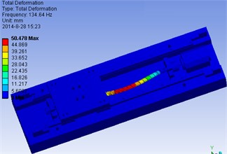
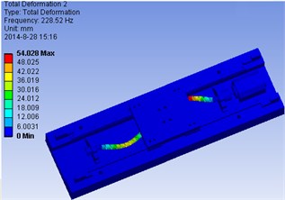
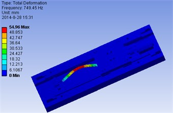
The model of the ball-screw feed drive system and its modal analysis are shown in Fig. 7. The detail simulation results are shown in Table 2. It can be seen from the results that the first several orders are obtained in different points. The screw-nut, a very important component, will affect the motion precision and dynamic performances.
Fig. 6Model of ball-screw feed drive systems excitation
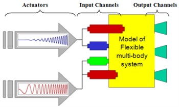
Fig. 7The model of ball-screw feed drive system and its modal analysis
a) Model of ball-screw feed drive systems
b) The 1st order model in point 1
c) The 2nd order model in point 2
d) The 3rd order model in point 3
4. Experimental verification
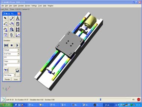
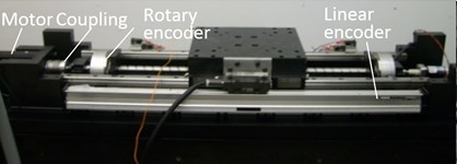
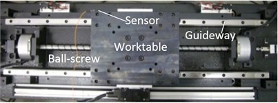
The single-axis ball screw feed drive system used for model verification is shown in Fig. 8. It consists of a ball screw constrained axially at the end closer to the motor by a thrust bearing. Another end farther from the motor is constrained using a radial ball bearing. It is driven by a DC motor connected to the ball-screw via a coupling. Position measurement can be obtained by two rotary encoders at either end of the ball screw and a linear encoder mounted to the table.
The modal test of the feed drive system can be seen in Fig. 8. The specifications used in the test system are: Cut/Pro (the modal testing and analysis software), USB Carrier I/O-9233 (for signal acquisition), accelerometer sensor 8778a500 (sensitivity: 10.00 mV/g), hammer 9722a500 (for excitation, with sensitivity 10.00 mV/g), sampling rate: 50000 Hz, frequency range: 100-1000, and transfer function: displacement-force. The first is the frequency response functions (FRF) between the torque applied to the motor through the amplifier and the angular displacements measured from the motor shaft.
The bandwidth of the drive’s amplifier used was 950 [Hz], therefore a frequency range of up to 1000 [Hz] was considered as the frequency range of interest for all of the measurements taken. Beyond this frequency range, the motor torque generated through the amplifier was severely attenuated and the measurements were corrupted. Three FRF characteristics were measured as follows:
Position 1: Table closer to the thrust bearing (i.e. around 50 [mm]);
Position 2: Table at the middle of its travel range (i.e. around 200 [mm]);
Position 3: Table closer to the radial bearing (i.e. around 350 [mm]).
Fig. 8Experimental setup and modal test of feed drive system
Exciting forces and responses were measured by using force sensor and acceleration sensor. According to the input point, output point, excitation force magnitude and direction of simulation, the experiment of exciting vibration were then carried out. The real part and imaginary of frequency curves of the vibration system in certain frequency range can be gained. Fig. 9 shows the corresponding experiment of exciting vibration in ball-screw feed drive systems. The frequency range of up to 1000 Hz was considered as the frequency range of interest for all of the measurements taken. Beyond this frequency range, the motor torque generated through the amplifier was severely attenuated and the measurements were corrupted.
Fig. 9Frequency response function in modal test
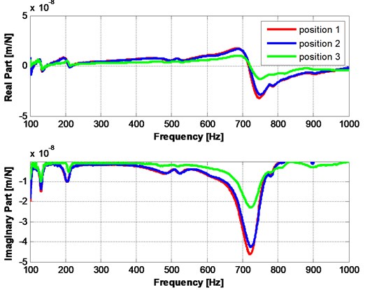
Table 2Compare FRF of simulation results and experiment of exciting vibration
Mode 1 [Hz] | Mode 2 [Hz] | Mode 3 [Hz] | |||||||
Position | Sim. | Mea. | Err [%] | Sim. | Mea. | Err [%] | Sim. | Mea. | Err [%] |
Pos. 1 | 134.6 | 122 | 8.95 | 229.15 | 210 | 8.23 | 755.09 | 722 | 4.57 |
Pos. 2 | 136.5 | 123 | 9.56 | 228.52 | 211 | 7.68 | 755.02 | 723 | 4.42 |
Pos. 3 | 135.2 | 124 | 8.14 | 229.40 | 215 | 6.11 | 749.45 | 724 | 3.34 |
From Table 2, it is clear that the FRF captured correctly the dynamic behaviors in three positions. It was able to accurately predict the relative natural frequencies and amplitudes of the modes and the way they varied as the table travels along the ball screw. However, some errors in predicting the exact natural frequencies of the modes as well as the exact amplitudes of the modes can also be seen. These predicted errors may mainly due to the inaccuracies in the joint stiffness values obtained from manufacturers’ catalogs. In addition, the friction, material non-uniformities and manufacturing and assembly errors in actual systems can influence the simulation results greatly. The screw-nut interface plays a major part on influencing the dynamic performance of the ball-screw feed drive systems. Therefore two methods for deriving the stiffness matrix of the screw-nut interface have been put forward. One of the methods is more suitable for short nuts while the other is intended for use with longer nuts and more flexible ball screws. Based on those extra cross-coupling terms, the finite element and virtual prototype model can give good qualitative insights into the influence of lateral vibrations on the mode shapes of the ball screw drive system and the axial positioning of the table.
In order to analyze the dynamic performance of the whole ball-screw feed drive systems based on the frequency response function in the modal test, the parameters of joint surfaces should be identified by combining the theory and experiments. The stiffness and damping ratio can be expressed as:
where, is the order natural frequency, and are the two extrema at the order real receptance, is the dynamic stiffness, is the amplitude of the i order natural frequency, is the damping ratio of the order natural frequency.
Fig. 10Transfer function (amplitude and real part) analysis in modal test
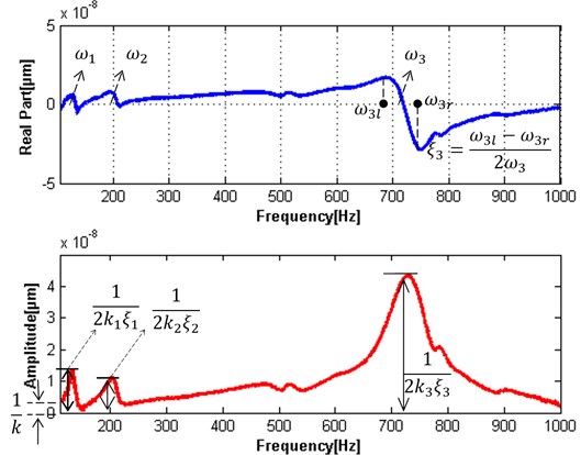
The static and dynamic stiffness and damping ratio can be identified respectively, as can be seen Fig. 10 (the amplitude and real part), based on Eq. (4) and Eq. (5) in the selected frequency range. The stiffness and damping ratio were enough. However, the first two order modals, as shown in the low frequency range, may influence the stability of machining processes. Some machining parameters should be optimized to avoid the lower nature frequency by increasing the bandwidth frequency. These parameters of joint surfaces (stiffness and damping) may not only help optimize dynamic performance of machine tool but also provide theoretical foundation and technology parameters for machining stability.
5. Conclusions
1) It is important to conduct the dynamic performance analysis and optimization of feed drive systems. The integration of the VP and FE method in one system provides the basis for simulating large movements and the performance of feed drive systems.
2) The integration method is sensible according to the experimental verification. This will provide a reference for dynamic optimal designs. The dynamic modeling of rigid-flexible coupling systems is based on the assumption that components are perfect. However, friction, material non-uniformities and manufacturing and assembly errors in actual systems will have large effects on simulation results.
3) The identified stiffness and damping ratio may provide a reference for structure design and technology parameters for machining stability. For future work, the control model of the feed drive system will be conducted and optimized to increase bandwidth and reduce displacement responses. This may improve dynamic performance of machine tool in the next stage.
References
-
Altintas Y. Manufacturing Automation. Cambridge University Press, Cambridge, UK, 2000.
-
Lida Zhu, Chunxia Zhu, Chong Su, Wanshan Wang Investigation on simulation and experiment of excitation characteristics of turn-milling center. Information – An International Interdisciplinary Journal, Vol. 14, Issue 12, 2011, p. 3875-3880.
-
Altintas Y., Brecher C., Weck M., Witt S. Virtual machine tool. Annals of the CIRP, Vol. 54, Issue 2, 2005, p. 651-670.
-
Varanasi K. K., Nayfeh S. A. The dynamics of lead-screw drives: low-order modeling and experiments. Transactions of ASME, Journal of Dynamic Systems, Measurement and Control, Vol. 126, 2004, p. 388-396.
-
Zhu C. X., Zhu L. D. Modeling of parallel robots in coordination with flexible multibody system and dynamic simulation. Journal of Northeastern University (Natural Science), Vol. 29, Issue 3, 2008, p. 366-370, (in Chinese).
-
Zaeh M. F., Oertli T., Milberg J. Finite element modelling of ball screw feed drive systems. Annals of CIRP, Vol. 53, Issue 1, 2004, p. 289.
-
Zaeh M., Siedl D. A New method for simulation of machining performance by integrating finite element and multi-body simulation for machine tools. Annals of the CIRP, Vol. 56, Issue 1, 2007, p. 383-386.
-
Okwudire C. E., Altintas Y. Modeling of the screw-nut interface of ball screw drives. ASME International Mechanical Engineering Congress and Exposition, Seattle, Washington, USA, 2007.
-
Chinedum E. Okwudire, Yusuf Altintas Hybrid modeling of ball screw drives with coupled axial, torsional, and lateral dynamics. ASME Journal of Mechanical Design, Vol. 131, Issue 7, 2009, p. 1-9.
-
Bae D. S., Han J. M., Choi J. H., Yang S. M. A generalized recursive formulation for constrained flexible multibody dynamics. International Journal for Numerical Methods in Engineering, Vol. 50, Issue 8, 2004, p. 1841-1859.
-
Xin Z., Yang R. Q. Theory and application of dynamic modeling of multi-flexible system. Mechanical Science and Technology, Vol. 21, Issue 5, 2002, p. 387-389.
-
Zr H., Oertli T. Finite element modeling of ball screw feed drive systems. Annals of the CIRP, Vol. 53, Issue 1, 2004, p. 289-294.
-
Kamalzadeh A., Erkorkmaz K. High bandwidth control of ball screw drives. Annals of the CIRP, Vol. 55, Issue 1, 2006, p. 393-398.
-
Simeon B. On Lagrange multipliers in flexible multi-body dynamics. Computer Methods in Applied Mechanics and Engineering, Vol. 195, 2006, p. 6993-7005.
-
Kamalzadeh A., Erkorkmaz K. Compensation of axial vibrations in ballscrew drives. Annals of the CIRP, Vol. 56, Issue 1, 2007, p. 373-378.
-
Chen J.-S., Huang Y.-K., Cheng C.-C. Mechanical model and contouring analysis of high-speed ball-screw drive systems with compliance effect. International Journal of Advanced Manufacturing Technology, Vol. 24, 2004, p. 241-250.
About this article

This work was supported by National Natural Science Foundation of China (NSFC) (51105258) and (51475087), and Supported by Program for Liaoning Excellent Talents in University (LJQ2014061) and Liaoning Key Laboratory Foundation (LZ2014016). Special thanks to the University of British Columbia-MAL for helping the theory and experimental setup.
