Abstract
In recent years publications for the blind people using Braille writing began to be produced on polymeric films. This has the advantage with respect to previous technologies, because such publications have longer time period till the time when their quality degrades and they become unacceptable for use. Plotting isoclinics for bending vibrations of a polymeric film using photo-elastic coatings is analyzed. The numerical procedure is based on the technique of conjugate approximation with smoothing. Improved smoothing procedure for two dimensional Lagrange quadratic elements is proposed. Composite isoclinic patterns with isoclinics for various directions of the vector of polarization in a plane polariscope are obtained. A single Braille element of the polymeric film on the basis of the plane strain problem is investigated. Nodal stresses are calculated by using the procedure of conjugate approximation. Equivalent stresses are represented by intensity of the image. Special experimental setup was created. Three samples were investigated: the first two samples were made from transparent polymeric film with Braille elements, the third sample was made from transparent polymeric film with Braille elements formed by the method of thermal shaping. The level of stresses is estimated in the static status of the sample and after rotations by various angles. For precise estimation of the stress fields photo-elastic images for a number of different values of the angle of rotation are required. Thus in this paper stresses in transparent polymeric films and Braille elements in them are investigated. The obtained results are used in the process of forming Braille elements in polymeric films.
1. Introduction
In recent years efforts are made to expand the possibilities of application of Braille writing using various materials. Among those materials transparent polymeric films play an important role. The researches [1, 2] carried out in the works show what effect have the materials for the Braille reading in which the prominent elements can be formed. The height of Braille, formed in paperboard books using embossing, after some time decreases and that affects the reading [3]. With the purpose to increase the time period of use of Braille elements till degradation of their quality polymeric materials can be used for production of books with Braille writings. During the process of reading and thus performing bending in a transparent usually optically isotropic polymeric material stresses develop. They have a negative effect to qualitative parameters of Braille elements [4]. In order to investigate the character of distribution of stresses in the polymeric material with elements of Braille writing the experimental method of photo-elasticity is used in this paper.
Special experimental setup was designed. It includes three main mutually interconnected devices: General Purpose Strain Viewer, digital camera and a personal computer. Three samples were investigated: the first two samples were made from transparent polymeric film (see Table 1) with printed Braille points, the third sample was made from transparent polymeric film with Braille points formed by the method of thermal shaping. The level of stresses is estimated in the static status of the sample and after rotations by various angles.
Table 1Physical parameters of investigated samples [5]
Parameter | Samples | |
Plastic PVC (samples 1, 2) | Plastic PVC (sample 3) | |
Modulus of elasticity, (MPa) | 2033 | 2033 |
Poissons ratio, | 0.42 | 0.42 |
Strength in tension, (MPa) | 51.7 | 51.7 |
Breaking elongation, (%) | 20 – 40 | 20 – 40 |
Impact strength, (MPa) | 2 – 4.5 | 2 – 4.5 |
Thickness of the material, (mm) | 0.08 | 0.8 |
Density of the material, (g/cm3) | 1.38 | 1.38 |
The stress field in a sheet of polymeric material used for Braille writing during the process of its bending is investigated. Numerical calculation and analysis of stresses in photo-elastic coatings is important in the process of measurement of stresses. Plotting isoclinics for bending vibrations of a sheet of polymeric film using photo-elastic coatings is analyzed in this paper.
The numerical procedure is based on the technique of conjugate approximation [6, 7] with smoothing [8] and the analysis of bending vibrations of a plate using photo-elastic coatings [9].
In this paper the improved smoothing procedure for two dimensional Lagrange quadratic elements is proposed, which has advantages over the conventional smoothing procedure. Composite isoclinic pattern with isoclinics for various directions of the vector of polarization in a plane polariscope is obtained. The investigations presented in this paper are considered as a continuation of investigations presented in the previous papers.
Investigations of stresses for separate Braille elements are performed. Plane strain problem is investigated. Nodal stresses are calculated by using the procedure of conjugate approximation. Equivalent stresses are represented by intensity of the image.
The numerical procedure is based on the technique of conjugate approximation [6, 7] and representation of equivalent stresses [10].
Special experimental setup was developed for investigation of polymeric films with Braille writings. The level of stresses is estimated in the static status of the sample and after rotations by various angles. From the obtained results of experimental investigations it is clear that for precise estimation of the stress fields photo-elastic images for a number of different values of the angle of rotation are required.
The purpose of this investigation is to determine the stress fields in polymeric films and elements of Braille writing. From the places of maximum stresses the failure of the material of polymeric film is expected to start.
2. Investigation of bending vibrations of a sheet of polymeric material
In the process of bending of a sheet of polymeric material stresses develop in it. They cause defects which lead to failure in dynamic regimes. Thus by using the model of polymeric material as of a plate and not taking separate Braille elements into account investigation of the stress field is performed in this section of the paper.
2.1. Improved smoothing procedure in photo-elastic measurements
and denote the axes of the system of coordinates. Local coordinates (, ) of the nodes are (–1, –1), (0, –1), (1, –1), (–1, 0), (0, 0), (1, 0), (–1, 1), (0, 1), (1, 1). , , …, are the shape functions of the two dimensional Lagrange quadratic finite element.
The nodal values of the stresses in the coating are determined from:
where , , are the vectors of nodal values of the stresses , , in the coating and:
where is the smoothing parameter and:
where , , , are the shape functions of the two dimensional Lagrange linear finite element with the nodes having local coordinates (–1, –1), (1, –1), (–1, 1), (1, 1).
2.2. Results of calculations of composite isoclinic patterns in the coating of a vibrating plate
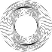
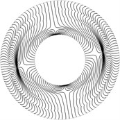
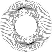
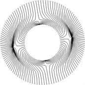
Circular plate with fixed internal radius is investigated. Composite isoclinic patterns for the second and the third eigenmodes obtained by using the procedure of conjugate approximation are presented in Fig. 1. The same results obtained by using the proposed procedure of conjugate smoothing are presented in Fig. 2.
Fig. 1Composite isoclinic patterns obtained by using the procedure of conjugate approximation for a) the second and b) the third eigenmodes
a)
b)
Fig. 2Composite isoclinic patterns obtained by using the proposed procedure of conjugate smoothing for a) the second and b) the third eigenmodes
a)
b)
From the presented results the applicability of the proposed procedure of conjugate smoothing is evident. The performed investigations indicate that the composite isoclinic patterns with isoclinics for various directions of the vector of polarization in a plane polariscope are important for the interpretation of the stress fields obtained in photo-elastic measurements. Thus a number of photo-elastic images for various directions of the vector of polarization by changing the angle of this vector with the x axis by a constant step are to be obtained in the experimental investigation. This helps in the interpretation of stress fields of a sheet of polymeric film.
3. Investigation of stresses in a separate Braille element
Blind people in the process of reading of information touch a separate Braille element with their fingers. This causes dynamic behavior of the carrier of information. Deterioration of quality of material usually starts at places with maximum stresses. Thus they are important in estimations of time to failure of the material.
Plane strain problem is investigated. Nodal stresses are calculated by using the procedure of conjugate approximation. Equivalent stresses are represented by intensity of the image.
3.1. Numerical procedure
, and denote the axes of the system of coordinates. Nodal values of the stresses are determined from:
where , , , are the vectors of nodal values of the stresses , , , and:
where:
where , , …, are the shape functions of the two dimensional Lagrange quadratic finite element.
Stresses in the expression of are determined from:
where is the vector of nodal displacements, is the matrix relating strains with displacements and:
where and . In the latter expressions is modulus of elasticity and is Poisson’s ratio.
Equivalent stress is determined as:
3.2. Investigation of the stress field for half of a circle
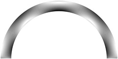
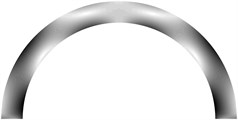
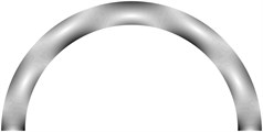
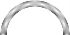
The structure consists of one row of elements located on half of a circle with radius of the middle line 0.001 m and semi thickness 0.0001 m. The following parameters are assumed: modulus of elasticity 20.3·108 Pa, Poisson’s ratio 0.42, density of the material 1380 kg/m3.
3.2.1. Static problem
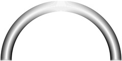
All displacements of the three nodes on the left end are assumed equal to zero. Displacements of the three nodes on the right end in the direction of the axis are assumed equal to zero and in the direction of the axis are assumed equal to one. Equivalent stresses are presented in Fig. 3.
Fig. 3Equivalent stresses
3.2.2. Eigenmodes
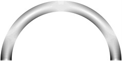
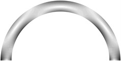
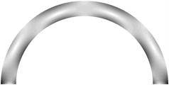
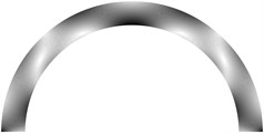
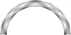
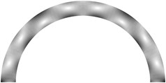
All displacements of the three nodes on the left end and of the three nodes on the right end are assumed equal to zero. Equivalent stresses for the first ten eigenmodes are presented in Fig. 4.
Fig. 4Equivalent stresses for a) the first, b) the second, …, j) the tenth eigenmodes
a)
b)
c)
d)
e)
f)
g)
h)
i)
j)
3.3. Investigation of the stress field for the structure with the straight part
The structure consists of one row of elements located on one fourth of a circle, of a straight part with the length equal to the length of the middle line of half of a circle and of another one fourth of a circle. The radiuses of the middle line of the parts of the circles are 0.001 m and semi thickness of the structure is 0.0001 m. The following parameters are assumed: modulus of elasticity 20.3·108 Pa, Poisson’s ratio 0.42, density of the material 1380 kg/m3.
3.3.1. Static problem
All displacements of the three nodes on the left end are assumed equal to zero. Displacements of the three nodes on the right end in the direction of the axis are assumed equal to zero and in the direction of the axis are assumed equal to one. Equivalent stresses are presented in Fig. 5.
Fig. 5Equivalent stresses

3.3.2. Eigenmodes
All displacements of the three nodes on the left end and of the three nodes on the right end are assumed equal to zero. Equivalent stresses for the first ten eigenmodes are presented in Fig. 6.
Fig. 6Equivalent stresses for a) the first, b) the second, …, j) the tenth eigenmodes

a)

b)

c)

d)

e)

f)

g)

h)

i)

j)
4. Experimental investigation of stresses of a sheet of polymeric film and Braille elements
A special experimental setup was produced for the investigation of distributions of stresses in investigated samples. It includes General Purpose Strain Viewer produced by the company Sharpless, digital camera EO-1312c and a personal computer (Fig. 7).
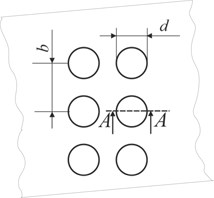
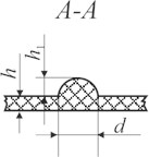
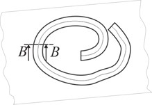
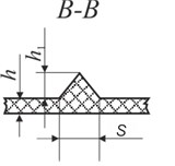
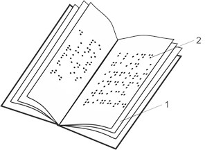
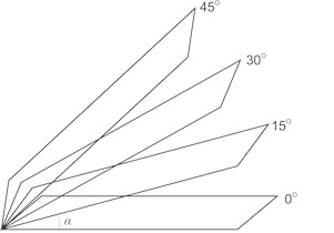
Three samples were investigated: the first two samples were made from transparent polymeric film with printed transparent Braille points, the third sample was made from transparent polymeric film with Braille points formed by the method of thermal shaping. Elements of Braille writing were formed of appropriate geometrical sizes (Fig. 8). The level of stresses is estimated in the static status of the sample and after rotations by the angles of 15°, 30° and 45°. Schematic representation of the sample in various states is presented in Fig. 9.
Fig. 7Structural diagram of the setup for investigation of stresses: 1 – light source; 2 – polarizer; 3 – plate of a quarter of a wave length; 4 – sample (polymeric film with Braille writing); 5 – background on which a sample is located; 6 – analyzer; 7 – digital camera EO-1312c; 8 – personal computer; S1 – direction of propagation of a light beam; S2 – direction of observation; α – angle of inclination of a polymeric film

Fig. 8Geometric parameters of surface graphical images (illustrations) and of Braille writing: a) upper view of Braille writing: d – diameter of point of Braille writing, b – distance between points of Braille writing; b) side view of Braille writing on polymeric material (A-A): h – thickness of polymeric material, h1 – height of point of Braille writing; c) surface graphical images; d) profiles of surface elements (B-B): h – thickness of polymeric material, h1 – height of graphical element, s – width of graphical element
a)
b)
c)
d)
Fig. 9Schematic representation of samples: a) a book consisting of sheets of polymeric film (1) with Braille writing (2); b) samples rotated by various angles α
a)
b)
The obtained photo-elastic images for the three samples for various values of the angle are presented in Table 2.
From the obtained results of experimental investigations it is clear that for precise estimation of the stress fields photo-elastic images for a number of different values of the angle of rotation are required. Interpretation of the results is based on Table 3.
It can be noted (see Table 2) that colour structure of stresses for samples 1 and 2 is different when angles of bending of a book change. When bending those samples by the angles of 15° and 30° colour regions of fourth order dominate. When bending those samples by the angle of 45° colour regions of the first order are noticed. In the process of bending it is observed that for the samples 1 and 2 not only the values of stresses change, but also their localisation changes. At the same time for sample 3 in the initial state residual stresses in the vicinity of Braille writing are observed (yellow colour), while during bending stresses do not experience substantial variations. Thus bending has small influence to the time to failure of the publication.
Table 2Photo-elastic images for the three samples for various values of the angle α
Sample 1 | Sample 2 | Sample 3 | |
Initial status 0° | 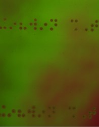 | 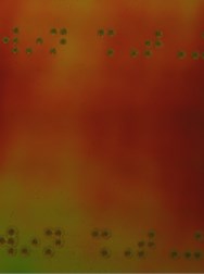 | 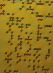 |
Angle of rotation 15° | 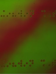 | 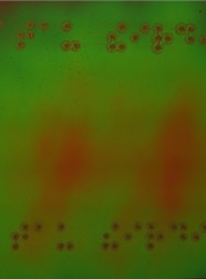 | 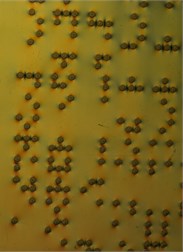 |
Angle of rotation 30° | 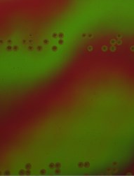 | 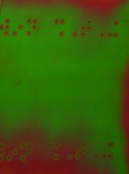 | 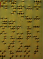 |
Angle of rotation 45° | 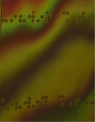 | 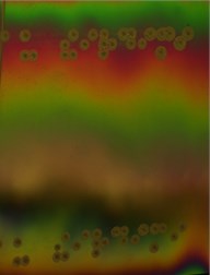 | 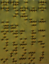 |
Table 3Rows of colour regions, which take place after lighting the sample with the source of white light [11]
Colour | Nanometers (10-9 m) |
First order colours | |
Black | 0 |
Grey | 140 |
White | 260 |
Pale yellow | 330 |
Orange | 460 |
Dull red | 520 |
Purple | 580 |
Deep blue | 620 |
Blue – green | 700 |
Colour | Nanometers (10-9 m) |
Second order colours | |
Green – yellow | 830 |
Orange | 960 |
Rose Red | 1050 |
Purple | 1150 |
Green | 1350 |
Third order colours | |
Green – yellow | 1450 |
Pink | 1550 |
Green | 1800 |
Fourth order colours | |
Pink | 2100 |
Green | 2400 |
From the results of the performed investigation it can be concluded that polymeric products with Braille writing formed by using the termoshaping method (sample 3) have longer time to failure. This is because of the fact that in the process of their bending stresses with lower values take place in them.
5. Conclusions
A sheet of polymeric material is investigated. Improved smoothing procedure for the analysis of stresses in the coating of a polymeric film performing bending vibrations is presented. The developed numerical procedure is based on the technique of conjugate approximation with smoothing using two dimensional Lagrange quadratic elements.
Composite isoclinic patterns are obtained. From the presented graphical results the applicability of the proposed procedure of conjugate smoothing is evident. The performed investigations indicate that the composite isoclinic pattern with isoclinics for various directions of the vector of polarization in a plane polariscope is important for the interpretation of the stress fields obtained in photo-elastic measurements. Thus a number of photo-elastic images for various directions of the vector of polarization are to be obtained in the experimental investigation.
A separate Braille element in a polymeric material is analyzed. Plane strain problem is investigated. Nodal stresses are calculated by using the procedure of conjugate approximation. Equivalent stresses are represented by intensity of the image. From the presented results the places with maximum stresses are determined.
A special experimental setup was developed. The level of stresses is estimated in the static status of the sample and after rotations by various angles. It is obtained that for precise estimation of the stress fields photo-elastic images for a number of different values of the angle of rotation are required.
Experimental investigations for three samples are presented: the first two samples were made from transparent polymeric film with printed points for transferring information by using graphical communications, the third sample was made from transparent polymeric film with points for transferring information by using graphical communications formed by the method of thermal shaping.
It is determined that polymeric products with Braille writing formed by the method of thermal shaping have longer times till failure, because in the process of their bending stresses with lower values take place.
Thus the general recommendation from the results presented in this paper follows: for precise investigation of the stress fields using photo-elastic experiments investigations of a number of photo-elastic images obtained for different values of the angles are to be performed.
The obtained results are used in the process of measurements of stresses in the elastic elements that are used for graphic communications.
References
-
Chen X., Barnes C. J., Childs T. H. C., Henson B., Shao F. Materials’ tactile testing and characterisation for consumer products’ affective packaging design. Materials & Design, Vol. 30 Issue 10, 2009, p. 4299-4310.
-
Childs T. H. C., B. Henson T. H. C. Human tactile perception of screen-printed surfaces: Self-report and contact mechanics experiments. Proceedings of the Institution of Mechanical Engineers, Part J: Journal of Engineering Tribology, Vol. 221, Issue 3, 2007, p. 427-441.
-
Graeme D., Robinson D., Weston A., Witakker J., Wilkins S. M. An investigation of the height of embossed Braille dots for labels on pharmaceutical products. Journal of Visual Impairment and Blindness, Vol. 103, Issue 10, 2009, p. 662-667.
-
Standard LST EN 15823: 2010 Packaging – Braille on Packaging for Medical Products.
-
Beswick R., Dunn D. Plastics in Packaging. Western Europe and North America. Rapra Technology Limited, 2002, 141 p.
-
Segerlind L. J. Applied Finite Element Analysis, 2nd Edition. New York, J. Wiley & Sons, 1984.
-
Gallagher R. H. Finite Element Analysis Fundamentals. Moscow: Mir, 1984, (in Russian).
-
Ragulskis M., Ragulskis L. Plotting isoclinics for hybrid photoelasticity and finite element analysis. Experimental Mechanics, Vol. 44, Issue 3, 2004, p. 235-240.
-
Ragulskis M., Ragulskis L. On interpretation of fringes produced by time average photoelasticity. Experimental Techniques, Vol. 29, Issue 3, 2005, p. 48-51.
-
Samul V. I. Basis of the Theory of Elasticity and Plasticity. Moscow. Vysshaja Shkola, 1982, (in Russian).
-
Sharples Stress Engineers Ltd. Manual for General Purpose Strain Viewer, www.sharplesstress.com.
