Abstract
Modal analysis is employed to analyze the vibration of temperature-dependent of Functionally Graded Plates (FGP) under a thermal environment in order to determine the natural frequencies and mode shapes. Theoretical formulation of various materials’ properties is done using the rule of mixtures. The natural frequencies and mode shapes of simply supported and clamped square plates are investigated as a function of crack, cutout, crack and cutout and temperature dependent properties. The Ansys program is employed for the purpose of analyzing the natural frequency and mode shape of a plate. Non-dimensional results are compared for temperature-dependent and temperature-independent FGP and subsequently validated according to known results obtained from the literature. Numerical results indicate the effect of crack, cutout, gradient index and temperature fields on the vibration characteristics and mode shapes. This study proves that natural frequency decreases with increasing gradient index () increasing the temperature and simultaneous presence of crack-cutout. In addition, clamped plates have a higher frequency than simply supported plates in all cases. Increasing temperatures lead to a maximum decrease in frequency at clamped FGP.
1. Introduction
In recent years, functionally graded materials (FGMs) have become an increasingly important area in applied engineering. FGMs are designed to be thermal barrier materials for aerospace structural applications and fusion reactors (Bayat, Saleem et al. 2009) [1]. One of the most significant aspects of this field is the vibration of FGP. Classical deformation theory was employed by Yang and Shen (2001) [2] to analyze the dynamic response of thin FGP subjected to impulsive loads. Deformation theories with temperature dependent material properties were employed by some researchers.Yang and Shen (2002) [3] studied the vibration of FGP in thermal environments. Shahrjerdi, Mustapha et al. (2011) [4] reported free vibration analysis of solar functionally graded plates (FGPS) with temperature dependent material properties using second order shear deformation theory. Shahrjerdi, Mustapha et al. (2011) [5] investigated the thermal free vibration of FGP. In aerospace structures, cut-outs are commonly found as access ports for mechanical and electrical systems, or simplay as weight reduction mechanisms. Cut-outs are also made to lighten the loads, provide ventilation and alter the resonant frequency of the structures. In addition, cracks can be present in structures as the result of various causes, such as fatigue and environmental factors like temperature Datta and Biswas (2011) [6]. Cracks present in vibrating components can lead to catastrophic failure as reported by Israr (2011) [7]. For these reasons, there is a need to employ cut-out in order to understand the dynamics of cracked structures. The vibration characteristics of structures can be useful for on-line detection of cracks without the structure actually having to be dismantled. To be specific, the natural frequencies and mode shapes of cracked plates can provide insights into the extent of damage.
Some studies have analyzed the natural frequencies of FGP through the use of cut-outs. Most of the investigations on plates with cut-outs have been confined to isotropic plates (1973) [8]; and Laminated composites by Ali and Atwal (1980) [3], Huang and Sakiyama (1999) [9], Reddy (1982) [10], Sivakumar, Iyengar et al. (1998) [11]. Recently, Janghorban and Zare (2011) [12] studied the influence of cut-outs on the fundamental frequency of FGP in thermal environments using FEM. Saji, Varughese et al. (2008) [13] reported on the analysis of the thermal buckling of FGP using cut-outs. Natarajan, Baiz et al. (2011) [14] proposed a method of determining the natural frequencies of cracked FGP.
Several studies have been conducted on the vibration of cracked FGP. The vibration of cracked plates was studied by Lynn and Kumbasar (1967) [15], who used a Green’s function approach. Later, Stahl and Keer (1972) [16] studied the vibration of cracked rectangular plates using elasticity methods. The other numerical methods used to study the dynamic response and instability of plates with cracks or local defects include the following: (1) Finite Fourier series transform (Solecki 1985) [17]; (2) Rayleigh-Ritz Method Khadem and (Rezaee 2000) [18]; (3) harmonic balance method (Wu and Shih 2005) [19]; and (4) finite element method (Guan-Liang, Song-Nian et al. 1991) [20]. Lee and Lim (1993) [21]. Recently, Huang, McGee III et al. (2011) [22] proposed solutions for the vibrations of side-cracked FGP based on Reddy third-order shear deformation theory using the Ritz technique. Yang and Hao et al. (2010) [23] studied the nonlinear dynamic response of an FGP with a through-width crack based on Reddy’s third-order shear deformation theory using the Galerkin method.
Most of the abovementioned papers deal with the natural frequencies of temperature-independent and dependent FGP with cut-outs or crack. Temperature-dependent materials in a constant temperature field and temperature variations with surface-to-surface heat flow through the thickness direction were considered in other research without any attention to crack and cut-out. Plates with cut-outs are extensively used in transport vehicle structures. Cut-outs are made to lighten the structure, for ventilation, to provide accessibility to other parts of the structures and to alter the resonant frequency. It is known that cracks or local defects affect the natural frequencies and resonant frequencies of a structural member. Additionally, temperature dependent material properties should be considered in the real conditions when the gradient of temperature cannot be neglected. To the authors’ knowledge, little work has been done in the area of the influence of a centrally located cut-out and cracks on the natural frequencies of temperature dependent FGP. In the present work, the FEM analysis is provided to determine the natural frequency of different boundary conditions’ FGP under temperature field. The temperature is assumed to be constant in the plane of the plate. The variation of temperature is assumed to occur only in the thickness direction. The temperature dependent FGP is considered. Material properties follow power law distribution in terms of the volume fractions of the constituents. This research aims to show the effect of material compositions, crack and cut-out and temperature fields on the vibration characteristics.
2. Material property of FGP
There are some models in the literature that express the variation of material properties in FGP (Shahrjerdi, Mustapha et al. 2011). FGPs are made of a mixture of two materials, namely a ceramic and a metal generality. It is usually assumed that the top surface of an FGP is ceramic rich while the bottom is metal rich. The region between the two surfaces consists of a blend of the two materials which is assumed in the form of a simple power law distribution.
2.1. Temperature independent material properties
According to a study reported by Shahrjerdi, Mustapha et al. (2011) [5], the material properties of FGPs are assumed to be position dependent and can be expressed as the following:
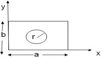
where () is coordinate in the thickness direction of an FGP; , , are effective material properties of the FGP, the properties of the ceramic and the properties of the metal respectively, , are the ceramic and metal volumes fraction, and () is the plate thickness. Power n is the volume fraction exponent. Here, a rectangular FGP in Cartesian coordinate system (, , ) with constant thickness (), width (), and length () is considered as shown in Fig. 1.
2.2. Temperature dependent material properties
Material properties of FGPs are assumed to be position and temperature dependent, according to the following relation (Shahrjerdi, Mustapha et al. 2011) [22]:
where denotes material property and indicates the environmental temperature; , , , and are the coefficients of temperature-dependent material properties unique to the constituent. In this section, mechanical and thermal analysis are carried out for an FGP; this entails a mixture of stainless steel (SUS304) and silicon nitride (Si3N4). The coefficients, ,, , , of stainless steel and silicon nitride are indicated by Sharjerdi (Shahrjerdi, Mustapha et al. 2011) [4].
Fig. 1FGP
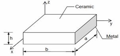
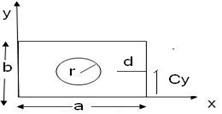
Fig. 2Cracked FGP
3. Crack formulation
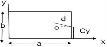
Crack may grow in different modes. We begin the crack analysis by considering the idealized case of a straight crack. For an FGP (Fig. 2), each of the displacement and rotation functions are assumed as sets of two functions in Eq. (3) (Huang, McGee III et al. 2011) [22]:
where are the displacement and rotation components in the , and directions, respectively, sets of functions indicated by the subscript “” consist of orthogonal polynomials, which form a mathematically complete set, if an infinite number of terms are used in Eq. (4); (Huang, McGee III et al. 2011) [22]:
where and are sets of orthogonal polynomials in the () and () directions of the rectangular plate reported by Bhat (1985). Sets of functions that describe the crack have been developed by Huang, McGee III et al. (2011). The sets of functions indicated by the subscript “” are to supplement the polynomials by characterizing the important features of the exact solutions along the crack in Eq. (5) (Huang, McGee III et al. 2011) [22]:
where functions are introduced to satisfy the geometric boundary conditions along 0, , 0, and and the origin of the () coordinate system is at the crack tip (Fig. 2).
Substituting Eq. (3), that is depend on the crack function Eq. (5), into Esq. maximum strain energy and maximum kinetic energy that they are reported by (Huang, McGee III et al. 2011) and minimizing the energy functional that is defined in Eq. (6) leads to a standard eigenvalue problem. The Eigen values being the natural frequencies of FGP, which is reported by Huang, McGee III et al. (2011) [22]:
where is maximum strain energy and the is maximum kinetic energy and they are a function of and material properties as reported by (Huang, McGee III et al. 2011) [22]. So FGP’s frequencies depend on the crack’s function, as seen in the Table 1 [22].
Table 1Natural frequencies for simply supported FGP with side cracks (h/b= 0.1)
Mode | |||||||
1 | 2 | 3 | 4 | ||||
0.2 | 0 | 0 | 0.5 | 5.363 | 12.82 | 12.82 | 18.56 |
0.2 | 45 | 0.75 | 5.352 | 12.79 | 12.82 | 18.29 | |
4. Modeling technique
A square plate is modeled by several layers. These layers capture a finite portion of the thickness and are treated like isotropic materials. The “layers” and their associated properties are then layered together to establish the through-the-thickness variation of material properties. Although the layered structure does not reflect the gradual change in material properties, a sufficient number of “layers” can reasonably approximate the material gradation. In this research, the modeling and analysis of FGP is carried out using ANSYS software. ANSYS offers a number of elements for the modeling of composite materials. Here eight layers are chosen. Solid186 is employed as type of element and meshing. The study of the behavior of a square FGP is done for a plate whose constituent materials are taken to be (SUS304), and (Si3N4). The top surface of the plate is ceramic (Si3N4) rich while the bottom surface is metal rich (SUS304). The geometry of the plate is chosen to be 0.1×0.1×0.01 m. The radius of circle cut-out is 0.005 m and the length of crack is 0.02 m. Table 2 shows different FGP geometries.
Fig. 3Square plate with 8 layers and meshing model
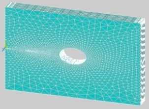
Table 2Geometry of FGP
Geometry of FGP | ||||||||||||||||
Cracked plate | Plate with central circular cutout | Cracked plate with circular cutout | ||||||||||||||
 |  |  | ||||||||||||||
0.1 | 0.1 | 0.01 | 0.2 | 0.5 | 0 | 0.1 | 0.1 | 0.01 | 0.1 | 0.1 | 0.1 | 0.01 | 0.2 | 0.5 | 0 | 0.1 |
Where , , , , and () are length, width, height and radius of cutout and location of crack respectively. | ||||||||||||||||
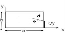
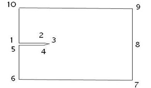
Fig. 3. shows a Square plate with 8 layers and a meshing model. A recommended geometry of opening crack is shown in Fig. 4.
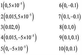
Fig. 4Modeling of crack
5. Boundary conditions
5.1. Mechanical boundary conditions
The boundary conditions that can be applied are simply supported Eq. (7), cantilever Eq. (8) and clamped Eq. (9), the displacement and rotation of which are defined in Eq. (7)-(9) respectively:
where , , , , are displacement in , , direction and rotation around and axes, respectively.
Consider a temperature load at the upper and lower surfaces, such as Eq. (10):
where , , and are temperatures of FGP, room, ceramic and metal, respectively. These thermal loads can be applied to solve the steady-state heat transfer Eq. (10) (Wu and Shih 2005):
The temperature distribution along the thickness can be obtained by solving a steady state heat transfer problem (Shahrjerdi, Mustapha et al. 2011):
where () is profile index and , are defined as thermal conductively coefficient of ceramic and metal, respectively.
6. Numerical results and validation
6.1. Verification and study
In order to validate the present research, intact FGP is modeled and subsequently compared according to the previous results. The results for temperature-dependent intact FGP, cracked FGP and cracked FGP with cut-out obtained by applying FEM are compared by the results (Rahimabadi, Natarajan et al. 2013) [24], (Huang and Shen 2004) [9] and (Natarajan, Baiz et al.) [15]. The dimensionless natural frequency parameter is defined as follows [8]:
where , , and are natural frequency of FGP, mass density, Young’s modulus and Poisson’s ratio of metal. Table 3 shows the dimensionless frequency of simply supported intact FGP in thermal environment obtained from the present work using Ansys in comparison with Ref. [24]. There is considerable agreement between the presented results and those from the study reported by (Rahimabadi, Natarajan et al. 2013) [24]. The main reasons which can explain the difference depend on the number of layers and the size of meshing. Moreover, the results for cantilevered FGP with a side crack and simply supported FGP with circular cut-outs are compared with other results [15, 9]. Table 4 shows the dimensionless frequencies for cantilevered FGP with a side crack ( 0.5, 0.5) as a function of gradient index.
Table 3Dimensionless frequency of simply supported FGP (a=b= 1; a/h= 8) in thermal environment
Simply supported FGP with central circular cutout 0.2, | Gradient index, | ||||
0 | 1 | ||||
Ref. [24] | Present | Ref. [24] | Present | ||
5 | 17.4690 | 18.254 | 10.5174 | 11.645 | |
20 | 17.5380 | 18.543 | 10.1776 | 11.134 | |
25 | 16.3587 | 17.006 | 9.1762 | 10.321 | |
From Table 5 dimensionless frequency for square FGP with circular cut-outs can be seen. The main reasons for the difference between the presented results in Tables 4, 5 and Ref. [9, 15, 24] are the number of layers and meshing size. Table 6 shows the dimensionless frequency of simply supported cracked FGP in a thermal environment obtained from the present work using Ansys in comparison with Ref. [22]. There is considerable agreement between the presented results and those from the study reported by (Huang, McGee III et al. 2011) [22]. The present approach is also compared to a conventional approach obtained by minimizing the energy functional in Eq. (6) in Table 7.
Table 4Dimensionless frequencies for cantilevered cracked FGP as a function of gradient index
Gradient index, | ( 0.5, 0.5) | |||
10 | 20 | |||
Ref. [13] | Present | Ref. [13] | Present | |
0 | 0.9951 | 1.031 | 1.0024 | 1.121 |
1 | 0.5973 | 0.674 | 0.6016 | 0.680 |
2 | 0.5372 | 0.601 | 0.5411 | 0.6102 |
Table 5Dimensionless frequencies for square FGP with circular cut-outs
Temperature ; | Gradient index | Mode 1 | Mode 2 | ||||
Ref. [24] | Ref. [9] | Present | Ref. [24] | Ref. [9] | Present | ||
400 K, 300 K | 0 | 12.315 | 12.397 | 13.362 | 29.031 | 29.083 | 30.10 |
0.5 | 8.484 | 8.615 | 9.589 | 19.986 | 20.215 | 21.975 | |
1 | 7.443 | 7.474 | 8.980 | 17.515 | 17.607 | 18.050 | |
600 K, 300 K | 0 | 11.894 | 11.984 | 12.125 | 28.436 | 28.504 | 29.95 |
0.5 | 8.269 | 8.147 | 9.120 | 19.535 | 19.784 | 21.001 | |
1 | 7.126 | 7.171 | 8.231 | 17.098 | 17.213 | 17.980 | |
Table 6Dimensionless frequencies for simply supported FGP with side crack (h/b=0.1, θ= 0, cy/b= 0.5, n= 1) as a function of crack function
Mode | ||||||||
1 | 2 | 3 | 4 | |||||
Ref. [22] | Present | Ref. [22] | Present | Ref. [22] | Present | Ref. [22] | Present | |
0 | 3.768 | 3.702 | 8.909 | 8.825 | 8.909 | 8.820 | 12.64 | 12.11 |
0.2 | 3.756 | 3.698 | 8.851 | 8.788 | 8.867 | 8.801 | 12.04 | 11.53 |
Table 7Natural frequencies for simply supported FGP with side cracks are obtained by minimizing the energy functional in Eq. (6) (h/b= 0.1)
Mode | ||||||||
1 | 2 | 3 | 4 | |||||
Ref. [22] | Present | Ref. [22] | Present | Ref. [22] | Present | Ref. [22] | Present | |
0.5 | 4.4220 | 4.101 | 10.620 | 10.231 | 10.621 | 10.233 | 16.201 | 15.876 |
6.2. Numerical results
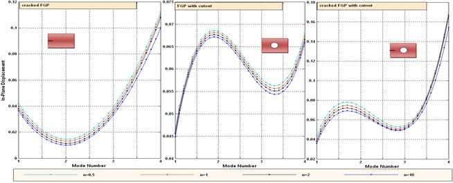
Tables 8-10 present the natural frequencies in Si3N4/SUS304 for different boundary conditions. In Tables 8-10, it can be seen that central cut-out, side cracked and cracked FGP with cut-out have maximum, medium and minimum frequencies at all temperatures, respectively. These results can be justified because the FGP with cut-out has less material than do the side cracked ones, which leads to decreased inertia momentums; therefore, the frequency of FGP with cut-out is greater than it is for the side crack ones. Furthermore, the natural frequency of cracked FGP with cut-out is less than it is in the two other cases. This is due to the decreasing stiffness of FGP. The effect of temperature on the frequencies can be investigated by considering the same value of shape mode and boundary condition. A clamped plate has a higher frequency than does a simply supported plate. The increase in the stiffness is the cause for the increase in frequency when the boundary condition is changed from simply supported to clamped condition, for a fixed aspect ratio and plate thickness. Fig. 5 shows the variation of in-plane displacement versus mode number of simply supported FGP for different values of gradient index (). It is obvious that the pattern of in plan displacement in cracked FGP with central cut-out is similar to FGP with central cut-out. This is due to the small size of crack. As gradient index increases, the in-plane displacements decrease slightly because of increasing metal content.
Table 8Dimensionless natural frequency parameter for temperature dependent simply supported FGP in thermal environments (n= 0.5)
Non-dimensional natural frequency 300, 300 K | |||||||||
Mode numbers of FGP (Si3N4 and SUS304) | 300 | 400 | 600 | ||||||
Side crack | Central cutout | Crack and cutout | Side crack | Central cutout | Crack and cutout | Side crack | Central cutout | Crack and cutout | |
1 | 0.5724 | 0.6098 | 0.5600 | 0.5550 | 0.6043 | 0.550 | 0.5590 | 0.5957 | 0.5469 |
2 | 1.3792 | 1.4548 | 1.3414 | 1.3277 | 1.4429 | 1.3270 | 1.3496 | 1.4224 | 1.3114 |
3 | 1.3797 | 1.4551 | 1.3429 | 1.3191 | 1.4453 | 1.3190 | 1.3501 | 1.4228 | 1.3128 |
4 | 1.4304 | 1.5827 | 1.4258 | 1.3332 | 1.5811 | 1.3330 | 1.4096 | 1.5619 | 1.3203 |
Table 9Non-dimensional natural frequency parameter for temperature dependent cantilever FGP in thermal environments (n= 0.5)
Non-dimensional natural frequency 300, 300 K | |||||||||
Mode numbers of FGP (Si3N4 and SUS304) | 300 | 400 | 600 | ||||||
Side crack | Central cutout | Crack and cutout | Side crack | Central cutout | Crack and cutout | Side crack | Central cutout | Crack and cutout | |
1 | 0.1102 | 0.1183 | 0.1090 | 0.1100 | 0.1175 | 0.1083 | 0.1077 | 0.1158 | 0.1067 |
2 | 0.2628 | 0.2762 | 0.2548 | 0.2609 | 0.2742 | 0.2529 | 0.2570 | 0.2702 | 0.2492 |
3 | 0.6515 | 0.6898 | 0.6363 | 0.6467 | 0.6847 | 0.6316 | 0.6370 | 0.6746 | 0.6223 |
4 | 0.7188 | 0.7487 | 0.6906 | 0.7125 | 0.7422 | 0.6844 | 0.7001 | 0.7293 | 0.6727 |
Table 10Dimensionless natural frequency parameter for temperature dependent clamped FGP in thermal environments (n= 0.5)
Non-dimensional natural frequency of cantilever FGP, 300, 300 K, 600 | |||
Mode numbers of | Side crack | Central cutout | Crack and cutout |
1 | 0.6764 | 0.8170 | 0.5054 |
2 | 1.3516 | 1.4623 | 0.9599 |
3 | 1.3727 | 1.4624 | 1.2660 |
4 | 1.8513 | 2.3102 | 1.5929 |
Fig. 5Variation of in-plane displacement versus mode number of simply supported FGP for different values of gradient index (n)
Tables 11, 12 show the contour plots of the transverse and in-plane displacement distribution for simply supported and cantilever FGP in different cases. Study of Table 11 indicates that by increasing mode number, variation of counter plot increases. It is obvious that there is no change in the first mode, while a change in the second and third modes is seen. The fourth mode is different for each item. This proves that the simultaneous presence of cracks and cut-out make more changes in higher modes. This is due to crack growth. Table 12 identifies transverse displacement distribution for cantilever FGP in different cases (Cracked FGP-FGP with cut-out and Cracked FGP with cut-out). First to third mode shape has no changes, while fourth mode has a variation.
Table 11Transverse displacement distribution for simply supported FGP in different cases (Cracked FGP-FGP with cut-out-Cracked FGP with cut-out)
Mode number | Different cases of FGP | ||
Cracked FGP | FGP with cut-out- | Cracked FGP with cut-out | |
1 | 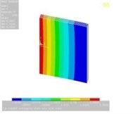 | 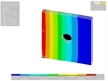 | 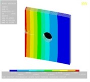 |
2 | 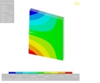 | 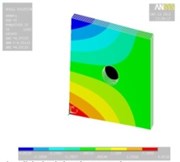 | 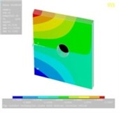 |
3 | 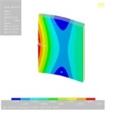 | 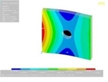 | 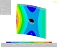 |
4 | 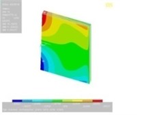 | 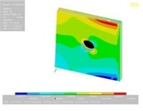 | 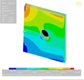 |
7. Conclusions
Detecting natural frequencies of temperature-dependent cracked FGP with cut-out can be an important problem in the mechanical field. Predicting the amount of frequency reduction due to cracks can be important in determining whether and to what extent the resonant frequency should be altered. Natural frequencies of intact FGP, cracked FGP and cracked FGP with cut-out subjected linear, temperature fields are investigated using FEM for simply supported, cantilever and clamped boundary conditions. Material properties of FGP are assumed to be temperature-dependent and vary in thickness by a power-law distribution in terms of volume fractions of constituents. The results are validated by comparing them with the results of other researchers. There is considerable agreement between the presented results and those from other studies. The main reasons which can explain the difference depend on the number of layer and size of meshing; therefore, using a greater number of layers and finer mesh gives more accurate results in comparing by experimental techniques. Moreover, the results for some important conclusions can be summarized as follows:
Percentage decrease of natural frequency due to crack for clamped boundary conditions has maximum reduction and minimum for simply support at different temperatures, which is due to an increase in the stiffness. The amount of frequencies reduction due to crack is about 30 %, 15 % and 7 % for clamped, cantaliver and simply supported boundary conditions, respectively.
Young’s modulus decreases with the increase in the temperature at different values of temperature of ceramic. A clamped plate has a higher frequency than a simply supported plate in all cases. An increase in stiffness is the cause for the increase in frequency when the boundary condition is changed from simply supported to clamped condition. The frequencies are decreased by increasing the temperature. Decreasing the Young modulus in all conditions leads to such results. The natural frequency of FGP with cutout is greater than it is for side crack ones. A decrease in the moment of inertia can be the main reason for this. Decreasing stiffness causes the natural frequency of cracked FGP with cutout to be less than it is in the two other cases. An increase in temperature leads to a maximum decrease of frequency at clamped FGP. The main reason for such a decrease depends on the decrease in the Young modulus. It can be seen that natural frequency in dependent temperature FGP is smaller than it is in the independent temperature properties. A similar conclusion was reported by (Shahrjerdi, Mustapha et al. (2011)). Stiffness in dependent temperature FGP is smaller than it is in the independent temperature one, which yields the mentioned conclusion. As gradient index increases, the in-plane displacements reduce slightly. This is due to increasing metal content.
Table 12Transverse displacement distribution for cantilever FGP in different cases (Cracked FGP-FGP with cut-out-Cracked FGP with cut-out)
Mode number | Different cases of FGP | ||
Cracked FGP | FGP with cut-out | Cracked FGP with cut-out | |
1 | 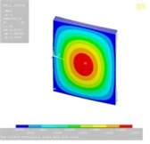 | 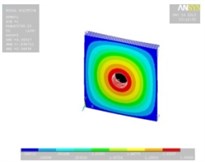 | 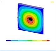 |
2 | 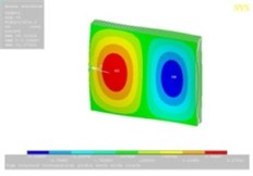 | 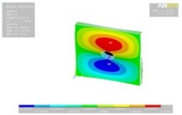 | 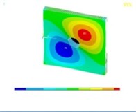 |
3 | 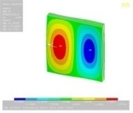 | 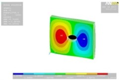 | 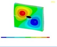 |
4 | 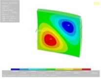 | 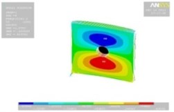 | 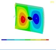 |
References
-
Ali R., AtwalS. Prediction of natural frequencies of vibration of rectangular plates with rectangular cutouts. Computers and Structures, Vol. 12, Issue 6, 1980, p. 819-823.
-
Bayat M., et al. Mechanical and thermal stresses in a functionally graded rotating disk with variable thickness due to radially symmetry loads. International Journal of Pressure Vessels and Piping, Vol. 86, Issue 6, 2009, p. 357-372.
-
Bhat R. Natural frequencies of rectangular plates using characteristic orthogonal polynomials in Rayleigh-Ritz method. Journal of Sound and Vibration, Vol. 102, Issue 4, 1985, p. 493-499.
-
Datta P. K., BiswasS. Research advances on tension buckling behavior of aerospace structures: a review. International Journal of Aeronautical and Space Sciences, Vol. 12, Issue 1, 2011, p. 1-15.
-
Guan-Liang Q., et al. A finite element model of cracked plates and application to vibration problems. Computers and Structures, Vol. 39, Issue 5, 1991, p. 483-487.
-
Huang C., et al. Vibrations of cracked rectangular FGM thick plates. Composite Structures, Vol. 93, 2011, p. 1747-1764.
-
Huang M., SakiyamaT. Free vibration analysis of rectangular plates with variously-shaped holes. Journal of Sound and Vibration, Vol. 226, Issue 4, 1999, p. 769-786.
-
Huang X.-L., ShenH.-S. Nonlinear vibration and dynamic response of functionally graded plates in thermal environments. International Journal of Solids and Structures, Vol. 41, Issue 9, 2004, p. 2403-2427.
-
Israr A. Model for vibration of crack plates for use with damage detection methodologies. Journal of Space Technology, Vol. 1, Issue 1, 2011.
-
Janghorban M., ZareA. Thermal effect on free vibration analysis of functionally graded arbitrary straight-sided plates with different cutouts. Latin American Journal of Solids and Structures, Vol. 8, Issue 3, 2011, p. 245-257.
-
Khadem S., RezaeeM. Introduction of modified comparison functions for vibration analysis of a rectangular cracked plate. Journal of Sound and Vibration, Vol. 236, Issue 2, 2000, p. 245-258.
-
Lee H., LimS. Vibration of cracked rectangular plates including transverse shear deformation and rotary inertia. Computers and Structures, Vol. 49, Issue 4, 1993, p. 715-718.
-
Lynn P., KumbasarN. Free vibration of thin rectangular plates having narrow cracks with simply supported edges. Developments in Mechanics, Vol. 4, 1967, p. 911-928.
-
Natarajan S., et al. Natural frequencies of cracked functionally graded material plates by the extended finite element method. Composite Structures, Vol. 93, Issue 11, 2011, p. 3082-3092.
-
Paramasivam P. Free vibration of square plates with square openings. Journal of Sound and Vibration, Vol. 30, Issue 2, 1973, p. 173-178.
-
Rahimabadi A. A., et al. Vibration of functionally graded material plates with cutouts and cracks in thermal environment. Key Engineering Materials, Vol. 560, 2013, p. 157-180.
-
Reddy J. Large amplitude flexural vibration of layered composite plates with cutouts. Journal of Sound and Vibration, Vol. 83, Issue 1, 1982, p. 1-10.
-
Saji D., et al. Finite element analysis for thermal buckling behaviour in functionally graded plates with cut-outs. International Conference on Aerospace Science and Technology, India, 2008.
-
Shahrjerdi A., et al. Free vibration analysis of solar functionally graded plates with temperature-dependent material properties using second order shear deformation theory. Journal of Mechanical Science and Technology, Vol. 25, Issue 9, 2011, p. 2195-2209.
-
Shahrjerdi A.,et al. Thermal free vibration analysis of temperature-dependent functionally graded plates using second order shear deformation. Key Engineering Materials, Vol. 471, 2011, p. 133-139.
-
Sivakumar K., et al. Optimum design of laminated composite plates with cutouts using a genetic algorithm. Composite Structures, Vol. 42, Issue 3, 1998, p. 265-279.
-
Solecki R. Bending vibration of a rectangular plate with arbitrarily located rectilinear crack. Engineering Fracture Mechanics, Vol. 22, Issue 4, 1985, p. 687-695.
-
Stahl B., KeerL. Vibration and stability of cracked rectangular plates. International Journal of Solids and Structures, Vol. 8, Issue 1, 1972, p. 69-91.
-
Wu G.-Y., ShihY.-S. Dynamic instability of rectangular plate with an edge crack. Computers and Structures, Vol. 84, Issue 1, 2005, p. 1-10.
-
Yang J., et al. Nonlinear dynamic response of a functionally graded plate with a through-width surface crack. Nonlinear Dynamics, Vol. 59, Issue 1-2, 2010, p. 207-219.
-
Yang J., ShenH.-S. Dynamic response of initially stressed functionally graded rectangular thin plates. Composite Structures, Vol. 54, Issue 4, 2001, p. 497-508.
-
Yang J., ShenH.-S. Vibration characteristics and transient response of shear-deformable functionally graded plates in thermal environments. Journal of Sound and Vibration, Vol. 255, Issue 3, 2002, p. 579-602.
About this article

