Abstract
This paper presents an efficient approach to simulate frequency and wave propagations in functionally graded material (FGM) bars by using novel weak form quadrature element method (WQEM). Based on Mindlin-Herrmann rod theory, a time domain N-node quadrature bar element is proposed. Detailed formulations are given. Dynamic problems of FGM bars are investigated by using the proposed weak form quadrature bar element. Comparisons are made with results obtained by using frequency domain spectral element method (SEM) and by using strong form differential quadrature method (DQM) to verify the developed quadrature bar element. It is shown that one 21-node bar element can yield very accurate frequencies and that the proposed element can efficiently simulate the wave propagation in FGM bars. Compared to results based on the simple rod theory, the results based on Mindlin-Herrmann rod theory should be more reliable, especially for the wave forms and group velocity.
1. Introduction
The material properties of functionally graded materials (FGMs) can be varied per desired spatial coordinates in such a way as to achieve desired mechanical, thermal, or electrical properties. This capability can help improve the strength and toughness of a structure. Therefore, FGMs have recently received a great attention in fields of aerospace, automobile, as well as electronics [1-13]. The problems of FGMs have been studied theoretically [1-6], approximately [7], and numerically [8-13].
Due to the complicated mathematical structure of the differential equations, it is not an easy task to obtain analytical solutions for general cases [2]. Therefore, various numerical methods, such as spectral element method (SEM) [10], differential quadrature method (DQM) [11], and finite element method (FEM) [10, 12, 13], and meshless method [8, 9] have been used to study the static, buckling, as well as the dynamic response of FGM bars, beams, circular and rectangular plates, cylinders and shells.
Although FEM is a very powerful computational method to deal with complex structural engineering problems, however, very fine meshes are usually needed to obtain accurate solutions, especially at the high frequency region [10]. The weak form quadrature element method (WQEM) [14], formulated based on the principle of minimum potential energy and differential quadrature rule, seems more flexible than the strong form differential quadrature method (DQM) [15]. It is shown that high accuracy can be achieved by the WQEM with smaller number of nodal points [14]. Besides explicit formulas for computing various derivatives of the displacement with respect to space variables at integration points are available, therefore, it is extremely simpler to formulate the stiffness and mass matrix of weak form quadrature elements with different number of nodes.
The purposes of this paper are two folds. One is to develop a weak form quadrature element model which has the capability to accurately predict the dynamics and wave propagations in FGM bars. The other is to investigate the dynamics and wave characteristics of FGM bars, namely, free vibration and wave propagation of FGM bars with radial variation of material properties. Based on Mindlin-Herrmann rod theory [16], a time domain N-node quadrature bar element is proposed. Detailed formulations are given. To validate the formulations, results are compared with existing data as well as solutions obtained by using the DQM. Based on the results reported herein conclusions are drawn.
2. Formulation of an N-node quadrature bar element
2.1. Expressions of strain energy and kinetic energy
For completeness considerations, the Mindlin-Herrmann theory [10, 16, 17] of a FGM bar with circular cross section shown in Fig. 1 is reviewed. The displacement fields is given by:
where is the axial displacement along the central axis of the bar and is the radial contraction.
Fig. 1Sketch of a circular three-layer cross section of the FGM bar
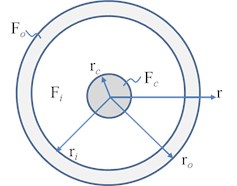
For comparisons, the circular cross-section of the FGM bar schematically shown in Fig. 1 consists of three layers with different materials, namely, the core (), the inner layer (), and the outer layer (), where is the outer radius of the circular cross section.
With Eq. (1), strains in the FGM bar can be expressed as:
where the prime denotes the first order derivative with respective to , subscripts , and denote the axial, radial and circumferential directions, respectively.
To match with three dimensional exact theory, two adjustment coefficients, denoted by , are introduced, namely [10, 16, 17]:
where is Poisson’s ratio of the bar material and is assumed the same for the entire cross section of the bar for simplicity. Note that the values of these two adjustment parameters were selected based on matching the limiting value of the first mode wave and setting a common tangent point for dispersion curves of different Poisson’s ratios [17], thus are approximate values. More details on the two adjustment coefficients may be found in [10, 16, 17].
For linear elastic materials, the strain energy of the FGM bar element with length is given by [10]:
where , , , and are defined by:
In Eq. (5), and are the well-known Lamé constants defined by:
where is the Young’s modulus of the FGM.
The kinetic energy of the FGM bar element with length is given by:
In Eq. (7), and are computed by:
where is the mass density of the FGM.
Let subscripts , , and represent the core, inner layer, and the outer layer. Assumption is made that elasticity moduli and mass densities in the core and the outer layer are uniform and that those in the inner layer are varying in the radial direction according to the power law given by [10]:
where is the non-negative power law exponent, and represents either the elasticity modulus or the mass density of the inner layer.
With the help of symbolic computing software Maple@, explicit formulas of , , , , in Eq. (4) and , in Eq. (7) can be easily obtained by substituting Eq. (9) into Eq. (5) and Eq. (8). Detailed expressions can be found in [10].
2.2. N-node quadrature bar element
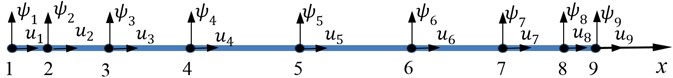
Consider an N-node weak form quadrature bar element, each node has two degrees of freedom, i.e., , (). A 9-node weak form quadrature bar element is skematically shown in Fig. 2.
Either Gauss quadrature or Gauss-Lobatto-Legendre (GLL) quadrature can be used for the numerical integration. After performing the quadrature, the strain energy of the bar element can be written as:
where are weighting coefficient of the first order derivatives with respect to at the integration point , and is the weight of the quadrature. Explicit formulas to compute are available. Details may be found in [14].
Fig. 2Sketch of a 9-node weak form quadrature bar element
Employing the row summation technique [18] and performing the quadrature, the kinetic energy can be expressed as:
where are the value of the Lagrange interpolation function at the integration point . If the integration points are also used as the nodal points of the element, one has .
The quadrature element equation of motion can be symbolically written as:
where the double over dots denote the second order derivative with respect to time, and [] and [] are mass matrix and stiffness matrix, respectively.
If the nodal displacement vector is defined as:
Then the elements in stiffness matrix [] are:
And the diagonal terms in mass matrix [] are:
For free vibration analysis, and where is the circular frequency. Thus Eq. (12) can be simplified as:
Solving the above equation by an eigen-value solver yields the frequencies and their corresponding mode shapes.
For wave propagations, Eq. (12) can be effectively integrated by using the central finite difference method, since the mass matrix is in diagonal form.
3. Results and discussion
To verify the proposed N-node quadrature bar element, the problem presented in [10], i.e., free vibration of a cantilever FGM bar is re-analyzed. The bar is axially uniform and made of Alumina (Al2O3) and mild Steel. The elasticity modulus and mass density are 390 GPa and 3950 kg/m3 for the Alumina, and 210 GPa and 7800 kg/m3 for the mild Steel. Poisson’s ratio is 0.3 for the entire bar. Geometries are 2 m, , and are 0.01 m, 0.009 m, and 0.001 m, respectively.
For comparisons, two types of FGM axial bars are considered. One type, denoted by ‘’, is that the core and the outer layer are made of Alumina and mild Steel. The other, denoted by ‘’, is that the core and the outer layer are made of mild Steel and Alumina. The bar is clamped at 0 and free at . Only one N-node quadrature bar element is used in the free vibration analysis. Thus the qudrature element mesh is similar to the one shown in Fig. 2, the only difference from the one shown in Fig. 2 is the number of nodes.
To show the convergence, different is used. Results and comparisons are listed in Table 1 and Table 2 for the two types of FGM.
Table 1Comparison of the natural frequencies (Ec>Eo, n= 1)
Mode | 1 | 2 | 3 | 5 | 10 |
Present ( 15) Present ( 19) Present ( 21) | 789.544 789.544 789.544 | 2368.59 2368.59 2368.59 | 3947.50 3947.50 3947.50 | 7104.59 7104.59 7104.59 | 15137.4 14987.0 14988.9 |
DQM ( 21) DQM( 101) | 789.544 789.544 | 2368.59 2368.59 | 3947.50 3947.50 | 7104.59 7104.59 | 14981.9 14988.9 |
SEM [10] | 789.955 | 2369.84 | 3949.65 | 7108.82 | 15001.8 |
In Table 1 and Table 2, the data cited from [10] are obtained by using one frequency domain spectral element. It is seen that the results obtained by using the DQM with the same number of grid points are similar to the ones by the weak form quadrature element method. Only the tenth mode frequency is sightly different. To improve the solution accuracy, 101 grid points are used in the DQ analysis. The DQ results with 101 should be accurate to be servered as the reference data. As expected, the data are not changed except for the the tenth mode frequency. It is seen that one 21-node weak form quadrature bar element can yield very accurate frequencies.
Table 2Comparison of the natural frequencies (Ec<Eo, n= 1)
Mode | 1 | 2 | 3 | 5 | 10 |
Present ( 15) Present (19) Present ( 21) | 1011.92 1011.92 1011.92 | 3035.73 3035.73 30335.73 | 5059.43 5059.43 5059.43 | 9106.21 9106.21 9106.21 | 19407.3 19213.7 19216.2 |
DQM ( 21) DQM( 101) | 1011.92 1011.92 | 3035.73 3035.73 | 5059.43 5059.43 | 9106.21 9106.21 | 19207.0 19216.1 |
SEM [10] | 1012.50 | 3037.52 | 5062.58 | 9112.87 | 19240.7 |
When Poisson’s ratio is zero, then Mindlin-Herrmann rod theory is reduced to the simple bar theory to some extent. The results are listed in Table 3 and Table 4. It is seen that one 21-node quadrature bar element can yield exactly the same results as the ones obtained by the DQM with 101 points. Comparisons of the results to the corresponding ones listed in Table 1 and Table 2 reveal that the difference caused by the two theories is very small and can be neglected in engineering applications.
Table 3The natural frequencies based on simple theory (Ec>Eo, n= 1)
Mode | 1 | 2 | 3 | 5 | 10 |
Present ( 21) | 789.546 | 2368.64 | 3947.73 | 7105.91 | 15001.3 |
DQM ( 101) | 789.546 | 2368.64 | 3947.73 | 7105.91 | 15001.4 |
Table 4The natural frequencies based on simple theory (Ec<Eo, n= 1)
Mode | 1 | 2 | 3 | 5 | 10 |
Present ( 21) | 1011.93 | 3035.78 | 5059.63 | 9107.33 | 19226.5 |
DQM ( 101) | 1011.93 | 3035.78 | 5059.63 | 9107.33 | 19226.5 |
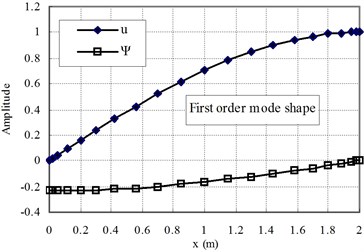
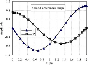
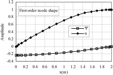
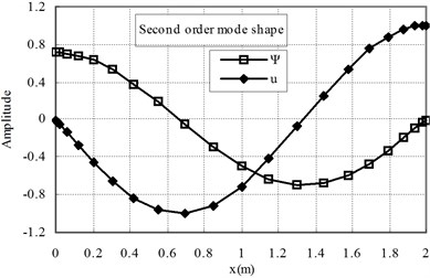
The first two mode shapes are shown in Fig. 3 for the cases of ( 1) and Fig. 4 for ( 1). The shapes are similar for the two cases. The variation of the radial contraction, , can be clearly seen. At the free end, is zero and at the fixed end, reaches its maximum value. Therefore, care should be taken to apply the fixed end boundary conditions, only 0 is applied and is not zero.
Next the axial wave propagations in two types of FGM bars are investigated by using the proposed quadrature bar element. Both ends of the bar are free. The geometries and material properties are the same as the ones in the free vibration analysis. The excitation signal is a five-peak tone-burst wave with a center frequency of 100 kHz [18] and is applied at 0. The axial waves are measured at the middle point of the bar (2).
Fig. 3The first and second mode shapes for the case of Ec>Eo (n= 1)
a)
b)
Fig. 4The first and second mode shapes for the case of Ec<Eo (n= 1)
a)
b)
In the numerical simulations, 60 equal length 9-node bar elements are used. Thus the model contains 481 nodes and 962 degrees of freedom. Since the mass matrix is a diagonal matrix, thus the equation of motion is explicitly integrated step by step by using the central difference method. A time increment of 5×10⁻⁸ s is used in the numerical integration. Differnt power law exponents are adopted in the investigations. Simulations are plotted in Fig. 5 and Fig. 6. Normalized amplitudes are shown.
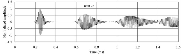
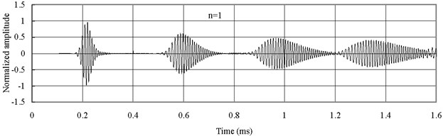
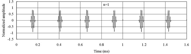
Fig. 5 displays the axial waves measured at 2 with type 1 FGM (). The axial waves are propagating in the FGM bars and then being reflected repeatedly from two free ends. The group velocity of the axial wave has the smallest value when 0.25. The group velocity of the axial wave increases with the increase of . Thus Fig. 5(c) shows that the axial wave when 4 is propagating faster than those when 1 and 0.25. Severe dispersion is observed.
Fig. 6 shows the axial waves measured at 2 with type 2 FGM (). The axial waves are propagating in the FGM bars and then being reflected repeatedly from two free ends. The group velocity of the axial wave has the largest value when 0.25. The group velocity of the axial wave decreases with the increase of , different from the previous cases. Thus Fig. 6(a) shows that the axial wave when 0.25 is propagating faster than those when 1 and 4. Besides the dispersion is not as severe as the one shown in Fig. 5.
Fig. 5Axial waves in the FGM axial bars with different n (Ec>Eo)
a)
b)
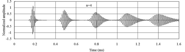
c)
It has been shown that the effect on the natural frequencies is negligible whether Mindlin-Herrmann rod theory or simple rod theory is used. To investigate the effect of the two different theories on the characteristic of wave propagation in the FGM bar, the axial waves measured at the middle point of the bar (1) are shown in Fig. 7 for and Fig. 8 for . Simple rod theory is used.
It is seen that the wave forms based on simple rod theory, whether or , are not dispersive. Comparisons of Fig. 7 and Fig. 8 with Fig. 5(b) and Fig. 6(b) reveal that the group velocity based on the simple rod theory is faster than the one based on Mindlin-Herrmann rod theory. Therefore, the results based on Mindlin-Herrmann rod theory should be more reliable.
Fig. 6Axial waves in the FGM axial bars with different n (Ec<Eo)
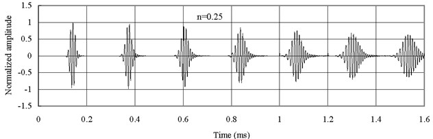
a)
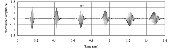
b)
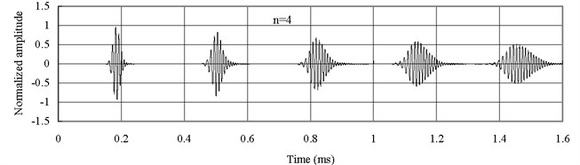
c)
Fig. 7Axial waves in the FGM axial bars based on simple rod theory (Ec>Eo)
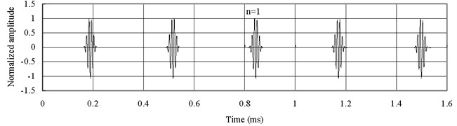
Fig. 8Axial waves in the FGM axial bars based on simple rod theory (Ec<Eo)
To give an explanation why the wave form for is more dispersive than the one for , the axial waves measured at the middle point of the bar are plotted in Fig. 9 for bar with material of Alumina (Al2O3) and Fig. 10 for bar with material of mild Steel. Poisson’s ratio is 0.3 and Mindlin-Herrmann rod theory is used.
Fig. 9Axial waves in the Alumina (Al2O3) bar
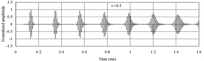
Fig. 10Axial waves in the mild Steel bar
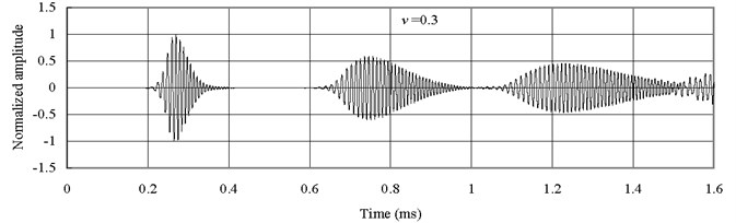
From Fig. 9 and Fig. 10, it is seen that the predicted wave forms based on Mindlin-Herrmann rod theory show dispersive even for bars with isotropic materials. The wave form in the bar with material of mild Steel is more dispersive than the one in the bar with material of Alumina. This is the reason why the wave form in the FGM bar is more dispersive for than that for , since the FGM bar contains more material of mild Steel.
It should be mentioned that the waves of are similar to the corresponding axial waves shown in Figs. 5 and 6, thus are ommitted for the space limitations.
4. Conclusions
Based on Mindlin-Herrmann rod theory, a novel weak form quadrature element method is proposed in this paper to analyze the dynamic behavior of FGM bars. A time domain N-node weak form quadrature bar element is formulated in detail. Dynamic problems of FGM bars are investigated by using the proposed quadrature bar element. For verifications, comparisons are made to results obtained by using frequency domain spectral element method and strong form differential quadrature method with large number of grid points. It is shown that one 21-node bar element can yield very accurate frequencies and that the proposed element can accurately simulate the wave propagation in FGM bars. Compared to results based on the simple rod theory, the difference on the nature frequencies corresponding to the axial vibration is negligible. However, the wave forms and group velocity are quite different. Therefore, Mindlin-Herrmann rod theory should be more reliable and useful in practice for wave propagation analysis.
References
-
Tutuncu N., Temel B. A novel approach to stress analysis of pressurized FGM cylinders, disks and spheres. Composite Structures, Vol. 91, 2009, p. 385-390.
-
Murín J., Aminbaghai M., Kuti V. Exact solution of the bending vibration problem of FGM beams with variation of material properties. Engineering Structures, Vol. 32, 2010, p. 1631-1640.
-
Arslan E., Eraslan A. N. Bending of graded curved bars at elastic limits and beyond. International Journal of Solids and Structures, Vol. 50, 2013, p. 806-814.
-
Huang Y., Li X. F. Buckling analysis of nonuniform and axially graded columns with varying flexural rigidity. Journal of Engineering Mechanics, Vol. 137, Issue 1, 2011, p. 73-81.
-
Torabi J., Kiani Y., Eslami M. R. Linear thermal buckling analysis of truncated hybrid FGM conical shells. Composites Part B: Engineering, Vol. 50, 2013, p. 265-272.
-
AkgÖz B., Civalek Ö. Longitudinal vibration analysis of strain gradient bars made of functionally graded materials (FGM). Composites Part B: Engineering, Vol. 55, 2013, p. 263-268.
-
Pradhan K. K., Chakraverty S. Free vibration of Euler and Timoshenko functionally graded beams by Rayleigh-Ritz method. Composites Part B: Engineering, Vol. 51, 2013, p. 175-184.
-
Ferreira A. J. M., Batra R. C., Roque C. M. C., et al. Natural frequencies of functionally graded plates by a meshless method. Composite Structures, Vol. 75, Issue 1-4, 2006, p. 593-600.
-
Neves A. M. A., Ferreira A. J. M., Carrera E., et al. A quasi-3D sinusoidal shear deformation theory for the static and free vibration analysis of functionally graded plates. Composites Part B: Engineering, Vol. 43, Issue 2, 2012, p. 711-725.
-
Hong M., Park I., Lee U. Dynamics and waves characteristics of the FGM axial bars by using spectral element method. Composite Structures, Vol. 107, 2014, p. 585-593.
-
Xiang H. J., Yang J. Free and forced vibration of a laminated FGM Timoshenko beam of variable thickness under heat conduction. Composites Part B, Vol. 39, Issue 2, 2008, p. 292-303.
-
Yu Z., Chu F. Identification of crack in functionally graded material beams using the p-version of finite element method. Journal of Sound and Vibration, Vol. 325, Issue 1-2, 2009, p. 69-84.
-
Alshorbagy A. E., Eltaher M. A., Mahmoud F. F. Free vibration characteristics of a functionally graded beam by finite element method. Applied Mathematical Modelling, Vol. 35, Issue 1, 2011, p. 412-25.
-
Jin C. H., Wang X., Ge L. Y. Novel weak form quadrature element method with expanded Chebyshev nodes. Applied Mathematics Letters, Vol. 34, 2014, p. 51-59.
-
Wang X., Wang Y., Yuan Z. Accurate vibration analysis of skew plates by the new version of the differential quadrature method. Applied Mathematical Modelling, Vol. 38, 2014, p. 926-937.
-
Mindlin R., Herrmann G. A one-dimensional theory of compressional waves in an elastic rod. Proceedings of the First US national congress of applied mechanics. Chicago, Illinois, 1951.
-
Yu C. P., Roesset J. M. Dynamic stiffness matrices for linear members with distributed mass. Tamkang Journal of Science and Engineering, Vol. 4, Issue 4, 2001, p. 253-264.
-
Ge L. Y., Wang X., Wang F. Accurate modeling of PZT-induced Lamb wave propagation in structures by using a novel spectral finite element method. Smart Materials and Structures, Vol. 23, 2014, p. 095018-14.
About this article

The project is partially supported by Funding of Jiangsu Innovation Program for Graduate Education (KYLX_0219), the Fundamental Research Funds for the Central Universities, and the Priority Academic Program Development of Jiangsu Higher Education Institutions.
