Abstract
In order to investigate the vibration characteristics of a rotating sandwich beam with magnetorheological (MR) fluid, the MR fluid can be simplified as linear and viscoelastic material. The finite element theory was applied to establish the finite element model of a two-node element with eight degrees of freedom for the rotating sandwich beam with MR fluid. Then the unit mass matrix and the unit stiffness matrix of the upper and lower surface elastic layers and the MR fluid of the middle layer were formed separately. And then, the equation of motion of the rotating MR fluid sandwich beams can be derived based on the Hamilton’s principle. The simulation provided the vibration characteristics of the sandwich beam under different magnetic field intensity and different rotating speeds. The result showed that the natural frequency and modal loss factor of the rotating MR fluid sandwich beam will increase with the increasing of magnetic field intensity. With the increasing of the rotating speed, the natural frequency of the rotating MR fluid sandwich beam will increase significantly and modal loss factor will reduce to some extent. So under the action of magnetic field, the MR fluid material can significantly influence the vibration characteristics of the rotating flexible beam.
1. Introduction
In recent years, with the development of material science, smart materials in the active control of structure vibration attract more and more attention in various fields. Shape memory material, piezoelectric and magnetostrictive material, MR fluid, electrorheological (ER) fluid, etc. have developed rapidly. The actuation performance of MR and ER material is more outstanding than others, which can change from fluid status into semisolid status in milliseconds when the external electrical or magnetic field was applied, and the change is reversible. As they response much faster than others, and they have wide dynamic range and low energy consumption and simple control mode and convenience to be buried, they have been widely applied in the civil, mechanical, aerospace and other fields.
Smart composite sandwich structure is the structure that composites smart material into the structure of beam or slab. As for the MR and ER fluid, many scholars at home and abroad have been engaged in the study of the dynamics characteristics of MR and ER sandwich structure. Rahn C. D. et al. established the dynamics model of ER fluid sandwich beam based on the theory of viscoelastic theory, and also controlled the vibration of the cantilever beam [1]. Choi S. B. analyzed the dynamics characteristics of ER fluid sandwich beam based on the combination of theory and experiment method [2]. Hu X. B. et al. established the dynamics equations of MR fluid sandwich beam, and found that the MR fluid under the action of additional magnetic field has outstanding vibration suppression on the sandwich beam based on the numerical simulation and experimental study [3]. Hu G. et al. made the experimental study of vibration response characteristic of MR elastomer sandwich beam under the action of non-uniform magnetic field [4]. Rajamohan V. et al. analyzed the vibration characteristics of a partially treated multi-layer beam with MR fluid. The results showed that the natural frequency and transverse displacement of the partially treated MR fluid sandwich beam not only related to the intensity of magnetic field, but also related to the location and the length of the fluid pocket [5]. Nayak B. et al. analyzed the dynamics characteristics of MR elastomer sandwich beam under different boundary conditions [6].
Wind turbine blades, helicopter rotor, turbine blades etc. can be simplified as a rotating flexible beam, in field of engineering. Wei K. X. et al. established a dynamic model of rotating ER fluid sandwich beam, and studied the vibration characteristics of the rotating ER fluid sandwich beam based on the combination of theory and experiment method. The results showed that under the action of applied electric field, ER materials can suppress the vibration of rotating flexible beam effectively [7]. Compared with ER fluids, the MR fluid has a greater yield stress and there is no safety problem of high voltage. Therefore, MR fluid has a broader application prospects in the field of vibration control of rotating flexible beam. But until now, few people have applied the magneto-rheological fluid material to the rotating flexible beam and made modeling analysis of its dynamics characteristics. In this paper, the finite element theory was used to establish vibration equation of rotary motion sandwich beam which contains MR fluid layer, and make research of the change rule of its natural frequency and modal loss factor by changing the magnetic field intensity and the rotating speed of the sandwich beam.
2. The dynamics modeling of rotating sandwich beam
The structure of rotary MR fluid sandwich beam is shown in Fig. 1. The top and bottom surface of sandwich beam are elastic constraint layers, and the middle layer is MR fluid layer. The beam whose length is and width is rotates around axis with the angular velocity of . The rotating axis’s radius is , and the thickness of each layer is . According to the classical theory of sandwich panels and MR fluid core layer’s characteristics, the following assumptions are used during the modeling process: (1) The thickness of each layer is much smaller than the length of the beam. (2) The shear deformation and damping of the elastic layer are ignored. (3) As the Young’s modulus of the MR fluid is negligible compared with the elastic layers, the axial stress of MR fluid layer is neglected. (4) There is no slip between two elastic layers and the MR fluid layer, and the lateral displacement and torsion angle of every point on the same cross section are equal. (5) The tangential displacement and axial deformation of every layer are both in the rotating plane.
Fig. 1The schematic diagram of rotating MR fluid sandwich beam
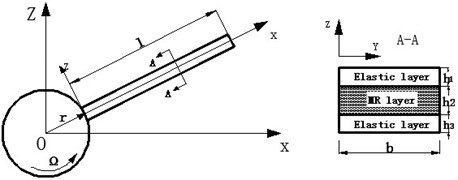
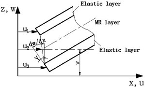
Fig. 2The deformation diagram of the MR fluid sandwich beam
2.1. The basic motion relations of sandwich beam
The strain displacement relationship between each layer is shown in Fig. 2. The axial displacement of the layers of the sandwich beams are , and , and the lateral displacement of each layer is , and the shear deformation of the MR fluid layer is , which can be described as follows [8]:
where:
Substituting Eq. (2) into equation Eq. (1), we have:
where .
Assuming that there is no axial force in the beam, and then we can get the deformation relationship between the top and bottom surface elastic layers as follows:
where , are the Young’s modulus of the top and bottom surface layer respectively. , are the cross-sectional area of the top and bottom surface layer respectively. And integration, we can get:
where .
2.2. Viscoelastic model of the MR fluid
For small amplitude motion of rotating MR fluid sandwich beam, MR fluid generally works in the pre-yield regime, performing viscoelastic properties. The stress and strain relationship can be expressed as [9]:
where is the shear stress. is the shear strain. is the complex shear modulus, and it can be written as following:
The relationship between the complex modulus and the intensity of the magnetic field of MR fluid can be expressed as [10]:
where (oersted) is the intensity of the magnetic field.
2.3. Shape function
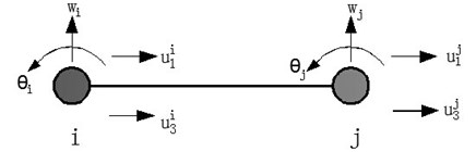
Based on the finite element method, a standard two-node beam element was established, and each node has four degrees of freedom (Fig. 3). The nodal displacement vector can be expressed as:
where is the horizontal displacement of beam, is torsion angle of the cross section, and , are axial displacement of upper and lower elastic layer.
Therefore, the displacement of any point within the element can be expressed as:
where , , and are given by the finite element shape functions:
where is the length of the element.
Fig. 3The two-node element of MR fluid sandwich beam
2.4. Dynamic model
2.4.1. The potential energy of sandwich beam element
For rotating MR fluid sandwich beam, regardless of the shear strain of the elastic layers and the tensile strain of the MR fluid layer, the potential energy of sandwich beam element consists of the bending and tensile strain energy of upper and lower elastic layers and shear strain energy of the MR fluid layer. Therefore, the potential energy of the rotating MR fluid sandwich beam can be expressed as:
where:
where , , are the stiffness matrix , , , , , are the Young’s modulus, moment of inertia and section area of the up and down elasticity layers, respectively.
2.4.2. The kinetic energy of sandwich beam element
Taking no account of the axial deformation of the MR fluid layer, the kinetic energy of the rotating sandwich beam element includes the kinetic energy caused by the transverse and axial movement of the upper and lower elastic layer and the kinetic energy caused by the bending motion of the MR fluid layer. Therefore, the kinetic energy of the rotating MR fluid sandwich beam can be expressed as:
where is the mass matrix of element:
where , , is the density of each layer.
2.4.3. Work caused by centrifugal force
If there is no external force acting on the sandwich beam, the work of the element is mainly caused by the centrifugal force [11]. The radial stress on any section at a distance from the left end of the th element is:
where is the rotating angular velocity, is the cross-sectional area of the sandwich beam, is the density of the sandwich beam, is the radius of the rotating shaft. Thus, the centrifugal force acting will be described as:
where .
2.4.4. The equation of motion of the sandwich beam
Substituting the Eq. (13), Eq. (14) and Eq. (16) into Hamilton variation equations, we have:
So, the vibration equation of the element can be obtained as:
where, is the mass matrix of the element, is the stiffness matrix, and:
According to the integrated unit method, the overall equation of motion of the rotating MR fluid sandwich beam can be obtained as:
This vibration system is the structural proportional damping system. In the Eq. (19), is the 8×8 order complex symmetric matrix. The complex eigenvalues of the system can be obtained as:
where, is the natural frequency of the structure, is the modal loss factor of the structure.
3. Simulation results and discussion
In order to verify the reliability and accuracy of the finite element modeling method for the rotating sandwich beam with MR fluid, parameters of the beam geometry and material of MRF sandwich are determined according to [3]. Then the natural frequencies and modal loss factor of sandwich beam were calculated when its rotating speed is zero. This means the beam is not a rotating one. The geometric and material parameters of the rotating MR fluid sandwich beam as follows: the length of the beam 0.38 m, the width of the beam 0.029 m; surface elastic layer uses aluminum alloy material with the thickness 0.0009 m, density 2800 kg/m3, modulus of elasticity 70 GPa. The thickness of MR fluid layer 0.001 m, density 3450 kg/m3. And the complex shear modulus can be obtained from Eqs. (8), (9).
It can be seen that the results of this method are basically consistent with the results of [3] according to Table 1, as for the natural frequencies and modal loss factors.
Table 1The first two natural frequencies and modal loss factors of the sandwich beam with rotation speed of zero compared with Ref. [3]
(oersted) | (Hz) | (Hz) | |||
0 | Ref. [3] | 11.85 | 30.21 | 0.0053 | 0.0025 |
Present | 11.65 | 34.22 | 0.0059 | 0.0020 | |
800 | Ref. [3] | 12.02 | 38.41 | 0.0061 | 0.0039 |
Present | 11.97 | 39.57 | 0.0063 | 0.0032 | |
From Table 1, it can be concluded that the finite element method can be effectively applied for the sandwich beam with MR fluid, because the first two natural frequency and modal loss factors the sandwich beam calculated in the paper can be consistent with those of the Ref. [3].
Then, it can be obtained a great many new conclusions when rotating speed was considered in the following parts.
The changing laws of natural frequency and modal loss factor of the rotating MR fluid sandwich beam can be obtained from numerical calculation, under the conditions of different rotating speed and different magnetic field intensity.
According to Fig. 4, when the rotating speed is zero, that means the MR fluid sandwich beam is static without rotating, the variation curves of the first two natural frequencies and modal loss factors of the sandwich beam changes with the magnetic field intensity. Thus, when the rotating speed is zero, with the magnetic field intensity increasing, the natural frequencies and modal loss factors of the MR fluid sandwich beams are gradually increasing. That is to say, the damping and stiffness of MR fluid sandwich beam increases greatly with the intensity of external magnetic field increasing.
Fig. 4The relationships between the natural frequency, modal loss factor of static MR fluid sandwich beam and the magnetic field intensity
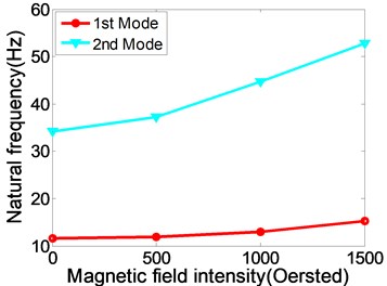
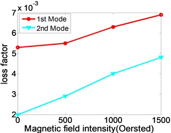
Fig. 5The relationships between natural frequency, modal loss factor of rotating MR fluid sandwich beam and the magnetic field intensity
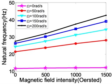
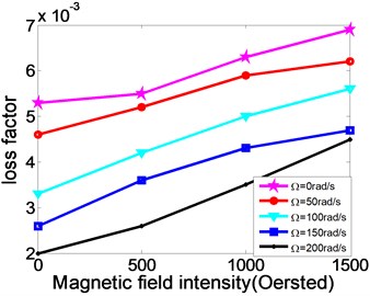
Fig. 6The relationship between natural frequency, modal loss factor and the changing rotating speed of MR fluid sandwich beam
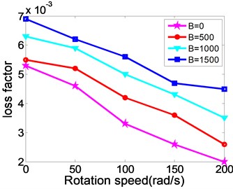
Fig. 5 illustrates that the relationships between natural frequency, modal loss factor of the rotating MR fluid sandwich beam and the magnetic field intensity.
From Fig. 5, the variation curves of the first natural frequencies and modal loss factors of the rotating MR fluid sandwich beam with the changing of magnetic field and different rotating speed. When the magnetic field intensity increases, the natural frequency and loss factors of the sandwich beam under different speeds are increased correspondingly. This is similar to the variation with the static sandwich beam under the different magnetic field intensity.
Fig. 6 shows the relationship between natural frequency, modal loss factor and the changing rotating speed of MR fluid sandwich beam. From the figure, when the rotating speed increases, the natural frequency of the MR fluid sandwich beam increases obviously while the loss factor of the MR fluid sandwich beam has been decreased. For example, when magnetic field is 500 oersted, and while 0 rad/s, the natural frequency of sandwich beam is 11.90 Hz, but while 50 rad/s, the natural frequency of sandwich beam directly increases to 23.75 Hz, increased by nearly 50 %. This is because the rotating speed increases, the centrifugal force caused by rotating increases, so the stiffness of the sandwich beam structure increases as well. But at the same rotating speed, the increasing the intensity of the applied magnetic field can make the loss factor of the structure increase significantly. Therefore, under an external magnetic field, the MR fluid material can increase the damping loss of the rotating flexible beam.
4. Conclusions
Based on the finite element method, a two-node element with eight degrees of freedom was established for a rotating sandwich beam with MR fluid. Then the equation of motion of the rotating sandwich beam was derived with Hamilton’s principle. The natural frequency and the modal loss factor of sandwich beams were discussed under different external magnetic field intensity and rotating speed. When the magnetic field intensity of the sandwich beam increases, the natural frequencies and modal loss factor of the rotating MR fluid sandwich beam will increase significantly. When the sandwich beam rotates quickly, the centrifugal force will increase correspondingly, this will make the stiffness of the structure dramatically increase and make the modal loss factor decrease. At the same rotating speed, the modal loss factor of the sandwich beam structure will increase significantly with the rising of magnetic field intensity. As a result, when the MR fluid material was filled into the flexible beam, the stiffness and damping of the structure will change with the intensity of magnetic field. In the future, maybe MR fluid used in this way will be utilized to suppress the vibration of the real flexible structure.
References
-
Rahn C. D., Joshi S. Modeling and control of an electrorheological sandwich beam. Journal of Vibration and Acoustics, Vol. 120, Issue 1, 1998, p. 221-227.
-
Choi S. B. Vibration control of a flexible structure using ER dampers. Journal of Dynamic Systems, Measurement, and Control, Vol. 121, Issue 1, 1999, p. 134-138.
-
Hu B. X., Zheng G. L., Xia P. Q. Study on the vibration of a sandwich beam with smart composites – MRF. Materials Science Forum, Vol. 546, 2007, p. 1649-1654.
-
Hu G., Guo M., Li W. H., Du H. P., Alici G. Experimental investigation of the vibration characteristics of a magnetorheological elastomer sandwich beam under non-homogeneous small magnetic fields. Smart Materials and Structures, Vol. 20, Issue 12, 2011, p. 1-7.
-
Rajamohan V., Rakheja S., Sedaghati R. Vibration analysis of a partially treated multi-layer beam with magnetorheological fluid. Journal of Sound and Vibration, Vol. 329, Issue 17, 2010, p. 3451-3469.
-
Nayak B., Dwivedy S. K., Murthy K. Dynamic analysis of magnetorheological elastomer-based sandwich beam with conductive skins under various boundary conditions. Journal of Sound and Vibration, Vol. 330, Issue 9, 2011, p. 1837-1859.
-
Wei K. X., Meng G., Zhang W. M., Zhou S. Vibration characteristics of rotating sandwich beams filled with electrorheological fluids. Journal of Intelligent Material Systems and Structures, Vol. 18, 2007, p. 1165-1173.
-
Mead D. J., Markus S. The forced vibration of a three-layer, damped sandwich beam with arbitrary boundary conditions. Journal of Sound and Vibration, Vol. 10, Issue 2, 1969, p. 163-175.
-
Yalcintas M., Dai H. Vibration suppression capabilities of magnetorheological materials based adaptive structures. Smart Materials and Structures, Vol. 13, Issue 1, 2004, p. 1-11.
-
Sun Q., Zhou J. X., Zhang L. An adaptive and dynamic characteristics of magnetorheological materials. Journal of Sound and Vibration, Vol. 261, Issue 3, 2003, p. 465-481.
-
Hoa S. V. Vibration of a rotating beam with tip mass. Journal of Sound and Vibration, Vol. 67, Issue 3, 1979, p. 369-381.
About this article

The work was supported by the Shanghai Natural Science Foundation under Grant No. 11ZR1414200.
