Abstract
A method of motion planning for a mobile manipulator taking into account damping the end-effector vibrations is presented. The primary task of the robot is to trace a given end-effector trajectory. The redundant degrees of freedom are used to fulfil secondary objectives such as minimisation of platform kinetic energy and maximisation of holonomic manipulability measure, which leads to reduction of the end-effector vibrations. The method is based on Jacobian pseudo inverse at the acceleration level. Nonholonomic constraints in a Pfaffian form are explicitly incorporated to the control algorithm. A computer example involving a mobile manipulator consisting of a nonholonomic platform (2, 0) class and SCARA-type holonomic manipulator operating in two-dimensional task space is also presented.
1. Introduction
A mobile manipulator is a robotic system consisting of a mobile platform and a manipulator mounted on its top. Growing interest in the use of robots of this type is caused by the fact that they combine the mobility of the platform and dexterity of the manipulator. The mobile platform significantly increases the operating range of the robot and enables the achievement of the desired position in the workspace, the dexterity of the manipulator allows to perform the precision tasks. For these reasons such a system can trace long trajectories (e.g. in inspection tasks) and perform tasks that require the movement of the robot to suitable position and orientation in which the manipulator traces a desired trajectory (e.g. welding, cutting, etc.).
The main mobile manipulator kinematic task is to track the desired end-effector reference trajectory as accurately as possible. Combining the mobile platform with manipulator causes that such a system gains kinematic redundancy. The redundant degrees of freedom render it possible to perform secondary tasks such as kinetic energy minimisation, ensuring the high manipulability measure, collision avoidance, fulfilment of the constraints imposed by robot mechanical limits, etc.
Much of existing research addresses such problems using only kinematic equations of the mobile manipulator. A kinematic control method based on the transverse function approach has been proposed by Fruchard et al. [1]. The realisation of the manipulation task has been set as the prime objective, the control objective for the platform has been expressed in the form of a secondary cost function, whose exact minimisation has been not a strict requirement. Bayle [2], [3] has proposed a pure kinematic solution based on the pseudo inverse of the Jacobian matrix. Galicki in [4] has presented a solution at the kinematic level to the inverse kinematic problem to solve point-to-point problems in a workspace with obstacles. In order to determine a unique solution, an instantaneous performance index describing an energy lost has been used. In [5] Seraji has proposed approach which treats nonholonomic constraints of the mobile platform and the kinematic redundancy of the manipulator arm in a unified manner to obtain the mobile manipulator motion at the kinematic level. Tchoń and Jakubiak [6] have solved the inverse kinematic problem for a mobile manipulator by applying an endogenous configurations that drive the end-effector to desirable positions and orientations in the task space. None of the works mentioned above considered the accuracy of the end-effector trajectory tracking. According to the author’s knowledge, this problem has been considered only in the work [7], which presents the solution of the mobile manipulator task at the control feedback level and analyzes the influence of the platform movement on the end-effector tracking error. It has been shown that non-zero speed of the platform during performing the task leads to undesirable end-effector vibrations that affect trajectory tracking accuracy.
In this paper the trajectory planning method for mobile manipulators taking into account the damping of the end-effector vibrations during tracing the given end-effector trajectory is presented. The work is limited to cases where the task can be accomplished only by the manipulator and the platform is used to move the robot to the suitable position and orientation. The robot trajectory is planned at the acceleration level in a manner to maximise holonomic manipulability measure and minimise kinetic energy of the platform. As can be seen in Section 2.2 this approach leads to damping the end-effector vibrations and reduction the end-effector tracking error. In order to solve such a task the Jacobian pseudo inverse method at the acceleration level with secondary objective functions is used. The solution of similar task presented in the work [7] requires transformation of nonholonomic constraints in a Pfaffian form to a driftless control system. This transformation is not unique which makes it difficult to choose a suitable driftless dynamic system. Opposite to this approach, the method presented here incorporates nonholonomic constraints in a Pfaffian form explicitly to the control algorithm. To the best of the author’s knowledge, no research has considered the damping of the end-effector vibrations taking into account nonholonomic constraints in such a way.
2. Problem formulation
Generally, the task of the mobile manipulator is to move the end-effector in the m-dimensional task space along the desired trajectory :
where function denotes -dimensional mapping, which describes the position and orientation of the end-effector in the workspace; is a vector of generalised coordinates describing a whole mobile manipulator composed of a nonholonomic platform and holonomic manipulator with kinematic pairs of the 5th class:
Vector depends on time , i.e. , means the vector of the coordinates of the nonholonomic platform, is the vector of joints coordinates of the holonomic manipulator; and determine the number of coordinates describing the nonholonomic platform and the holonomic manipulator, respectively, .
Introducing the end-effector tracking error defined as:
the task of the mobile manipulator can be presented in a more general form as:
The above form of the problem formulation includes cases where manipulator is at the initial moment away from the desired trajectory . This situation often occurs when using mobile robots, because a nonholonomic part allows to extend workspace of the mechanism and is used to move the robot in place of the goal task.
Using the mobile manipulators involves additional kinematic constraints, that reduce their local mobility. These constraints are in general nonholonomic and can be described in the Pfaffian form:
where is (×) Pfaffian full rank matrix and is the number of nonholonomic constraints.
The dependencies Eqs. (4)-(6) formulate the robotic task, in the next section the Jacobian pseudo inverse trajectory planning method is presented to solve this problem.
3. Trajectory generation at the acceleration level
To solve the problem defined in the above section, the approach based on author’s previous works [8-10] on trajectory planning for mobile manipulators is used. In Section 2.1 the classic Jacobian pseudo inverse method at the acceleration level, for solving task defined by dependencies Eqs. (4)-(6), is presented. Next, it is shown that the movement of the platform during performance of the task Eq. (1) leads to undesirable end-effector vibrations that result in trajectory tracking error. The way to eliminate this drawback of the algorithm is shown in Section 2.2.
3.1. Jacobian pseudo inverse method
In order to solve the problem Eq. (4)-(5) with constraint Eq. (6), the end-effector tracking error Eq. (3) has to be extended as follows:
where ; denotes (×) null matrix.
The mapping may be interpreted as some measure of error between a current configuration and that fulfilling constraints Eq. (1) and Eq. (6) for a given time instant . Furthermore, mappings ,…, are responsible for moving the end-effector along a given trajectory and the mappings ,…, are responsible for the fulfilment of nonholonomic constraints Eq. (6).
For simplicity of further calculations the following notation is introduced:
where , and .
In order to solve the trajectory planning problem, the following system of differential equations is proposed (see works [11] and [12] for stationary manipulators):
where , are (×) diagonal matrices with positive coefficients ensuring the stability of the first equation, and is (×) diagonal matrix with positive coefficients ensuring the stability of the second equation.
The dependence Eq. (9) is a system of homogeneous differential equations with constant coefficients. Proposed form of the equations ensures that their solution is asymptotically stable for positive coefficients , and . The property of asymptotic stability implies fulfilment of the dependencies Eqs. (4) and (5), additionally if nonholonomic conditions are fulfilled at the initial moment of the motion (e.g. if initial velocity is equal to zero), they are also fulfilled during the entire movement. Moreover, compliance dependence Eq. (4) guaranties that mobile manipulator will approach the desired trajectory if at the initial moment the manipulator is away from it and finally will execute the task Eq. (1).
In order to obtain the trajectory of the mobile manipulator Eq. (9) can be rewritten in an explicit form:
where .
After simple calculations the system of Eq. (10) can be represented as:
where .
To determine right pseudo inverse [13] of is introduced as:
and the trajectory of mobile manipulator can be obtained from the following differential equation:
The method described above allows to find trajectory of mobile manipulator in such a way that the end-effector performs task Eq. (1) and nonholonomic constraints Eq. (6) are taken into account, however, it has a significant drawback. Combination of the mobile platform with the manipulator causes that even relatively simple constructions have high number degrees of freedom and may be redundant for many tasks. The example of such a task is presented in next section: robot composed of a SCARA type manipulator mounted on a unicycle, traces a circle trajectory. The existence of redundant degrees of freedom makes it possible to perform the task in many different ways. From a practical point of view, it seems that the mobile platform should be used to place the manipulator in the appropriate position and its participation in the task execution should be as small as possible. Because the solution presented above does not impose any additional conditions on the motion of the platform, during the execution of sample task both platform and manipulator motion occurs. In this case, the motion of the platform is undesirable because it causes unnecessary energy consumption. Moreover, it introduces vibrations of the end-effector (as is shown in work [7]), which affect the accuracy of the trajectory tracking (Figs. 6 and 7). The method of reduction of these vibrations is presented in the next section.
3.2. End-effector vibrations reduction
As shown above, using the method of trajectory planning based on dependence Eq. (13) can lead to undesirable end-effector vibrations. The reason of this drawback is the movement of the platform during the execution of the primary task Eq. (1). It seems, that the platform should be used to achieve the appropriate position and orientation of the mobile robot and the task ought to be done primarily by using holonomic manipulator. As a consequence an additional constraint imposed on platform velocity should be considered in the following form:
Redundant degrees of freedom make it possible to introduce the secondary mobile manipulator task, which allows to reduce the platform movement to necessary ones during the execution of the task only. This approach will lead to minimising the platform movement when the task can be done by the manipulator. Furthermore, the platform location ensuring high manipulability of holonomic part increases dexterity of the manipulator and additionally will reduce movement of the platform. Finally, to reduce undesirable end-effector vibrations two secondary objective functions are used: the first one minimises the platform motions and the second one provides high manipulability measure of the holonomic manipulator.
To take into account secondary objective the method for stationary manipulators proposed in the work [13] is used. In the case of trajectory planning method for mobile manipulators, discussed in this paper, dependence Eq. (13) is generalised by adding an additional component as follows:
where denotes (×) identity matrix and is an acceleration vector which is suitably chosen to optimise a secondary objective function. In order to reduce the end-effector vibrations, it is proposed to determine vector in such a way as to optimise the following performance index:
where is known from variational principles of mechanics as a Helmholtz kinetic potential [14] of a unit mass with coordinate . Mapping denotes a manipulability measure of holonomic part defined in the work [15]. The second term of the cost function can be interpreted as the kinetic energy of the mobile robot.
To minimise performance index Eq. (16) the steepest descent techniques may be used:
where is small positive coefficient, denotes variational derivative of functional with respect to function . Based on the calculus of variation, can be determined as (see, e.g. work [16] for stationary holonomic manipulator):
After simple algebra, taking into account dependencies Eqs. (16)-(18), vector can be obtained as:
The above form of the acceleration vector allows to optimise two secondary objectives: the first term leads to maximisation of the holonomic manipulability measure and the second one leads to minimisation of the mobile manipulator kinetic energy, thus reducing its velocity. It seems that influence of these components should depend on the stage of the task accomplishment. If or (end-effector is far from desired trajectory) the velocity reduction is undesirable because it causes an increase of the task execution time. If , (end-effector achieves desired end-effector trajectory) keeping the high manipulability measure of holonomic part forces platform movements even if the task can be performed by the holonomic manipulator. Taking into account the above considerations, introduction of two coefficients (depending on the end-effector distance from trajectory) damping the components of vector is proposed. The influence of the component describing kinetic energy is reduced when the end-effector is away from the trajectory and the component describing the manipulability measure is damped when , . Additionally, the reduction of kinetic energy should only affect the platform (the holonomic manipulator performs the task), so the trajectory of the mobile manipulator is described as follows:
where denotes -dimensional zero vector and is non-negative function whose values decreases when , . The exemplary form of function is:
Mobile manipulator trajectory obtained from differential Eq. (20) ensures execution of the task Eq. (1) and simultaneously fulfils the nonholonomic constraints Eq. (6). Moreover, the obtained solution allows to reach the desired trajectory with high holonomic manipulability measure, which makes it possible to perform the task without the use of the platform movements. Additionally, minimisation of platform kinetic energy leads to fulfilment of constraint Eq. (14) and decreases the platform movement when the desired trajectory is reached. The above features of the proposed solution imply significant reduction of the end-effector vibrations and therefore eliminate the main drawback of the method presented in Section 2.1.
4. Numerical example
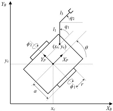
In the numerical example, a mobile manipulator consisting of a nonholonomic platform of (2, 0) class (where denotes the platform’s degree of mobility, represents the number of steering wheels which can be oriented independently) and a SCARA type holonomic manipulator working in a two-dimensional task space is considered. In order to increase the degree of its redundancy, the orientation of its end-effector is not taken into consideration. A kinematic scheme of the mobile manipulator is shown in Fig. 1.
The mobile manipulator is described by the vectors of generalised coordinates:
where is the platform centre location, is the platform orientation, , are angles of driving wheels and , are joints’ angles of the holonomic manipulator.
The platform works in plane of the base coordinate system . The coordinate system is attached to the mobile platform at the midpoint of the line segment connecting the two driving-wheels. The holonomic manipulator is connected to the platform at the point of system. The kinematic equation of mobile manipulator is given as:
where and are the lengths of the manipulator arms.
Fig. 1Kinematic scheme of the mobile manipulator
The motion of the platform is subject to one holonomic and two nonholonomic constraints, so constraints Eq. (6) in this case take the following form:
where is the radius of driving wheels, and is half-distance between the wheels.
The kinematic parameters of the mobile manipulator are given as (all physical values are expressed in the SI system):
The task of the manipulator is to trace for 30 seconds an end-effector trajectory described by the following equation:
In order to compare trajectory generators introduced in Section 2, two cases of performing this task are considered. In the first one the trajectory of the mobile robot is determined using the dependence Eq. (13), in the second one extended trajectory generator Eq. (20) is used. In both cases the values of gain coefficients are assumed as: 1.0, 2.0, 3.0. In the initial moment of the motion the mobile manipulator does not move, the platform centre is in position 0, , its orientation amounts and configuration of the holonomic manipulator is taken as , . In this configuration the mobile manipulator is away from the desired trajectory which is out of the end-effector range, so the task accomplishment is divided into two stages. In the first one the mobility of the platform is used to achieve the position where the trajectory is in the end-effector range (end-effector tracking error is close to zero), in the second one the primary task Eq. (1) is accomplished. In both simulations the first stage takes about 10 seconds.
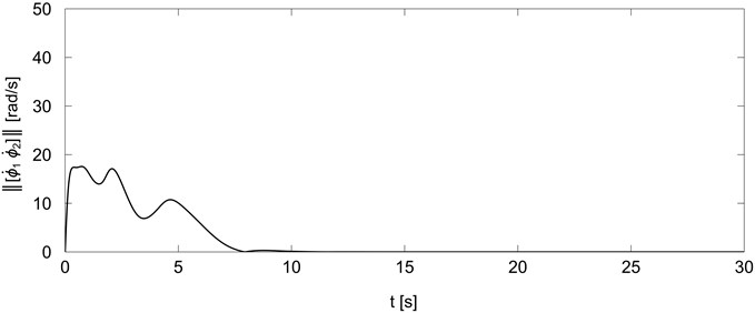
Figs. 2 and 3 present the norm of platform wheels velocities during the execution of the task for generators Eqs. (13) and (20) respectively. As can be seen in Fig. 2 the platform moves even when the trajectory is achieved and the mobile manipulator performs the primary task (). In this case the task is realised simultaneously by the mobile platform and holonomic manipulator. In the second simulation (Fig. 3) the platform moves only in the first stage of the task accomplishment. The platform wheels velocities decrease when the end-effector closes to given trajectory (the tracking error converges to zero) and the influence of component responsible for the minimisation of the platform kinetic energy increases. The platform stops after about 10 seconds and remains immobile during the primary task accomplishment.
Fig. 2Norm of platform wheels velocities for trajectory generator Eq. (13)
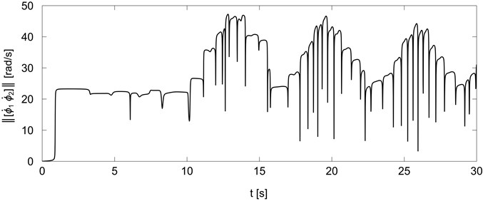
Fig. 3Norm of platform wheels velocities for trajectory generator Eq. (20)
Changes of the manipulability measure of the holonomic manipulator are presented in Figs. 4 and 5. As can be seen from Fig. 4 in the first simulation the manipulability measure has a large amplitude changes in both the first and the second stage of the task. For trajectory generator Eq. (20) the manipulability measure remains at a high level in the first stage of the task execution when the mobile robot closes to desired trajectory. This allows to achieve high dexterity of holonomic manipulator after stopping the platform (10 s) and involves small changes of manipulability measure during task accomplishment.
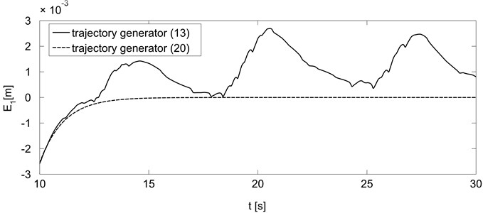
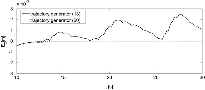
Figs. 6 and 7 present comparison of the end-effector tracking errors for trajectory generators Eqs. (13) and (20). For clarity of presentation the first stage of the task execution is omitted and the tracking errors are depicted only for the second stage when the primary task is accomplished. As can be seen use of the generator Eq. (13) leads to undesirable end-effector vibrations, which affect the accuracy of the task giving trajectory tracking errors of the order of 10-3 [m]. Introducing the secondary objective function Eq. (19) in trajectory generator Eq. (20) leads to stopping the mobile platform (Fig. 3) and obtaining high manipulability measure of the holonomic manipulator (Fig. 5), which affects significant reduction of end-effector vibrations and increases the trajectory tracking accuracy.
Fig. 4Holonomic manipulability measure for trajectory generator Eq. (13)
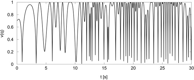
Fig. 5Holonomic manipulability measure for trajectory generator Eq. (20)
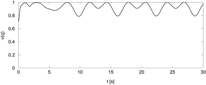
Fig. 6End-effector tracking error E1 for trajectory generators Eqs. (13) and (20)
Results of numerical simulations presented above confirm the correctness of the proposed method of the end-effector vibration reduction introduced in Section 2.2. All simulations have been carried out in a Matlab 7 environment running on an ordinary personal computer with Intel Core i7 processor. The sampling time in each simulation has been equal to 0.01 s, computational times have been comparable to the resulting execution times. The obtained results confirm a computational effectiveness of presented approach and indicate that the method can be used to real-time trajectory planning.
Fig. 7End-effector tracking error E2 for trajectory generators Eqs. (13) and (20)
5. Conclusion
In the paper a motion planning method for a mobile manipulator tracing given end-effector trajectory is presented. The considerations are limited to cases where the platform is used to move the robot to the suitable position and orientation in the workspace and the primary task is accomplished only by the manipulator. Unlike most of the existing research, this work takes into account the end-effector vibrations arising by the movement of the platform and leading to undesirable end-effector tracking errors. Moreover, the proposed method incorporates nonholonomic constraints in a Pfaffian form explicitly to the control algorithm, which allow to avoid constraints transformation to a driftless control system.
The problem is solved at the acceleration level by using Jacobian pseudo inverse method with secondary tasks such as maximisation of the holonomic manipulability measure and minimisation of the platform kinetic energy. This solution ensures that mobile manipulator achieves the given trajectory with a high manipulability measure of the holonomic part and accomplishes the task with zero platform velocity. As shown by the numerical simulations this approach leads to reduction of the end-effector vibrations and significantly increases trajectory tracking accuracy. Moreover, the obtained results indicate that this method may be used to on-line trajectory planning.
This work is limited to trajectory planning tasks that can be accomplished only by using the holonomic manipulator, however, the presented method may be used also to perform the tasks that require the movement of the platform. In such cases, the secondary task of minimising platform kinetic energy will not stop the platform, but it will reduce its movement as little as possible. Additionally, introducing to the proposed trajectory generator an additional component taking into account the influence of the obstacles it is possible to use this method to collision-free trajectory planning.
References
-
Fruchard M., Morin P., Samson C. A framework for the control of nonholonomic mobile manipulators. International Journal of Robotics Research, Vol. 25, Issue 8, 2006, p. 745-780.
-
Bayle B., Fourquet J. Y., Renaud M. A coordination strategy for mobile manipulation. 6th International Conference on Intelligent Autonomous Systems (IAS-6), Venice, Italy, 2000, p. 981-988.
-
Bayle B., Fourquet J. Y., Renaud M. Manipulability of wheeled mobile manipulation: application to motion generation. International Journal of Robotics Research, Vol. 22, Issue 7-8, 2003, p. 565-581.
-
Galicki M. Inverse kinematics solution to mobile manipulators. International Journal of Robotics Research, Vol. 22, Issue 12, 2003, p. 1041-1064.
-
Seraji H. A unified approach to motion control of mobile manipulators. International Journal of Robotics Research, Vol. 17, Issue 2, 1998, p. 107-118.
-
Tchoń K., Jakubiak J. Endogenous configuration space approach to mobile manipulators: a derivation and performance assessment of Jacobian inverse kinematics algorithms. International Journal of Control, Vol. 76, 2003, p. 1387-1419.
-
Galicki M. Two-stage constraint control of mobile manipulators. Mechanism and Machine Theory, Vol. 54, 2012, p. 18-40.
-
Pająk G., Pająk I. Motion planning for mobile surgery assistant. Acta of Bioengineering and Biomechanics, Vol. 16, Issue 2, 2014, p. 11-20.
-
Pająk G., Pająk I. Sub-optimal trajectory planning for mobile manipulators. Robotica, 2014, p. 20.
-
Pająk G., Pająk I. Collision-free trajectory planning for mobile manipulators subject to control constraints. Archive of Mechanical Engineering, Vol. 61, Issue 1, 2014, p. 35-55.
-
Pajak I., Galicki M. The planning of suboptimal collision-free robotic motions. 1st International Workshop Robot Motion and Control, 1999, p. 229-243.
-
Pajak G., Galicki M. Collision-free trajectory planning of the redundant manipulators. 6th International Conference Methods and Models in Automation and Robotics, Vol. 2, 2000, p. 605-610.
-
Siciliano B., Sciavicco L., Villani L., Oriolo G. Robotics. Modeling, Planning and Control. Springer, 2009.
-
Rubinowicz W., Krolikowski W. Theoretical Mechanics. Warsaw PWN, 1980, (in Polish).
-
Yoshikawa T. Manipulability of Robotic Mechanisms. The International Journal of Robotics Research, Vol. 4, Issue 2, 1985, p. 3-9.
-
Galicki M. Optimal planning of a collision-free trajectory of redundant manipulators. The International Journal of Robotics Research, Vol. 11, Issue 6, 1992, p. 549-559.
About this article

