Abstract
Reproducing the real behavior of brake judder in time domain is useful for brake judder reduction, but it is hard to establish a time-domain model of brake judder due to the effects of thermo-mechanical coupling. To solve this problem, a modeling method is proposed taking into account the effects of thermo-mechanical coupling before hotspot occurs. In this method, an eight-degree-of-freedom dynamics model of brake caliper assembly with multi-contact points is established, and a semi-empirical model of friction coefficient is proposed by magic formula tyre model. The input of the dynamics model is the initial disc thickness variation (DTV) and the DTV caused by uneven heating, which is calculated by a transient FE model of thermo-mechanical coupling considering initial DTV. On this basis, a simulation of brake judder is conducted and an experiment is designed to validate the method. The simulated brake pressure and brake torque without and with thermo-mechanical coupling are compared with the experiment results respectively, and it indicates that the simulated results considering thermo-mechanical coupling have a good agreement with experiment results. Brake pressure variation (BPV) and brake torque variation (BTV) increase gradually in time domain because of the effects of thermo-mechanical coupling and the increments of BPV and BTV can reach 45 % and 50 % respectively in the simulation.
1. Introduction
Brake judder is one of the most important brake NVH problems, and it is a forced vibration and its frequency is usually less than 100 Hz which is proportional to vhicle speed. According to the traditional classification [1, 2], brake judder is mainly grouped in two categories, which are cold judder and hot judder. Cold judder is mainly caused by initial DTV and LRO, hot judder is mainly caused by thermal deformation. Brake judder can induce the vibration of suspension, steering wheel, brake pedal, instrument panel and car body, and it closely concerns passengers’ comfort of driving and usually leads to serious customer complains. Therefore, brake judder always attracts the attention both of the industry and academia in recent years and it is meanful to establish the simulation model to predict brake judder accuratly and save the labor, time and cost.
The theoretical studies of brake judder can be identified in two groups. One group of researchers has focused on the transfer path issues. They mainly study the transfer path of (BTV) through chassis elements to steering wheel and car body etc, and analyze the sensitivity of chassis elements to brake judder reduction. Kim et al. proposed a mathematical model of suspension corner using multi-rigid-body dynamics [3], then the multi-rigid-body models of vehicle chassis system were established [4-7]. Hwang et al. put foward a finite element model which was made by the lumped mass, beam, and rigid elements [8]. In order to improve the accuracy of the simulation, Chen et al. created a multi-rigid-flexible coupling model of a vehicle [9], and then some nonlinear factors including the stiffnesses of bushings, the clearance of rack-pinion gear and the damping properties of tire patches were considered [10-12].
The second group of researchers has focused on the source considering the brake components. They mainly evaluate BTV and the acceleration of caliper and analyze the sensitivity of brake components to brake judder. Jacobsson proposed a rotor-stator model [13] and then developed an extended model including pads, piston and caliper with initial DTV [14]. After that, the initial DTV was considered to be the input in brake judder modeling. Leslie established a dynamic model of a whole brake caliper assembly [15], and Dreyer et al. put forward a simpilified elasto-kinematic model of pads and caliper [16]. Kim et al. defined caliper, carrier, pads, guide rods and knuckle as flexible body and proposed a flexible multi-body dynamic model of brake corner [17]. In recent years, many studies focused on the nonlinear charateristics of brake judder. Jaeyoung et al. considered brake pad nonlinear stiffness that changed with brake pressue [18], Heckmann et al. took into account the disc-pad contact stiffness the clearance of journal bearings [19], and Sen et al. considered speed-dependent friction torque excitation in a nonlinear torsional mathematical model of a disc-flywheel system [20]. In addition, Duan et al. proposed a simplified source-path-receiver model [21], in which the source, path and nonlinear characteristics are both taken into account.
Although the above brake judder simulations have a great progress and play important roles on barke judder analysis and reduction, these models have some shortages. For example, most of these studies analyzed brake judder in frequency domain and neglected the characteristic in time domain. Many researchers have pointed out the time-domain model should be increasingly used to solve brake NVH problems [1, 2], but the simulation of brake judder in time domain has two main difficulties. On the one hand, brake mechanical motion including the initial DTV and disc rotation is hard to simulate. On the other hand, the effects of friction heating is hard to consider in the simulation. Thermo-mechanical coupling exists in brake friction heating [22], and the experiment results show that DTV and BTV increase sharply with disc temperature and the brake judder become severe [23, 24]. Kim et al. [17] considered the brake mechanical motion and also found the phenomena of brake judder worsening by experiment, but the simulation results do not reproduce the characteristics because of neglecting the effects of thermo-mechanical coupling.
Judder simulations considering the effects of uneven heating are present by thermo-mechanical models of brake associated with hot spots reproduction [25-28]. In these studies, BTV is calculated by the normal contact force on the pad, but the acceleration of caliper can not be predicted. Although the main purpose of these studies is to reproduce hot spot, unfortunately there is no consensus about the machanism of hot spots now. Barber and Lee proposed the theory of thermoelastic instability (TEI) [29, 30], and this theory plays an important role in this research field. But Kao et al. proposed thermoelastic unstable buckling was the significant factor to hot spots [25], which is different from TEI. Panier et al. proposed a theory of progressive waviness distortion (PWD) considering disc plastic flow and yielding [31]. Not only that, Altuzarra believed that the effect of tangential vibration causes hot spot [26]. In addition, the initial DTV and LRO are not considered in these thermo-mechanical model of hot spots, and it can be inferred that brake judder does not occur before the hot spots appear in their simulations.
From the temperature amplitude point of view, hot spots occur when the disc surface temperature is above 300°C [24] and the angular temperature gradient is above 100°C [32], and the temprature threshold of cold judder is usually taken as 100°C [33-35]. Thus the effects of thermo-mechanical coupling should be considered when the disc surface temperature is above 100°C. But most studies considering the effects of thermo-mechanical coupling are interested in the temperature range of hot spots, and the effects of thermo-mechanical coupling in the middle temperature range from 100°C to 300°C are little involved.
The objective of the present study is to analyze brake judder in time domain considering the effects of thermo-mechanical coupling in the middle temperature range with the initial DTV and LRO. In this paper, a brief review of brake judder modeling and simulation is presented firstly. In Section 2, a 8DOF vibration model considering multi-points contact between pads and disc is proposed to predict brake judder in theory. In Section 3, a semi-empirical model of friciton coefficient is specified using magic formula tyre model. In Section 4, thermo-mechanical coupling modeling and simuation including initial DTV is carried out to identify the judder excitation under uneven heating. In Section 5, the simulation results without and with thermo-mechanical coupling and experiment results compared with each other to validate the theroretical analysis. Finally, some concluding remarks are presented in Section 6.
2. Modeling of disc brake judder
2.1. A dynamic model of disc brake with multi-points contact
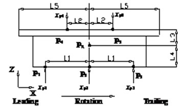
On the basis of the simplified model proposed by Dreyer [16] and the truth of the uneven contact between disc and pads, multi-points contact is supposed in brake pads. Fig. 1 shows the position of contact points in brake pad. , and are the contact points between disc and pad and they are in the brake equivalent radius evenly. According to the rotation direction in Fig. 1, is near leading edge, is at the center of brake equivalent radius, and is near trailing edge. and are the contact points between inner pad and piston, or the contact points between outer pad and caliper. is the tangential direction of and is normal direction of disc surface. is the distance between , and in direction and 2×10⁻² m. is the distance between , and the central line in direction. In order to express clearly, and are defined as the distances of inner pad andouter pad respectively, and 1.62×10⁻² m and 3.25×10⁻² m. is the mass center of brake pad. and are the distances between and pad surfaces in direction respectively, and 7.5×10⁻³ m and 1.25×10⁻² m. is the distance between leading edge, central line and trailing edge in direction and 6.4×10⁻² m. , , , and are the displacements of contact points in direction.
Fig. 1The position of contact points in brake pad
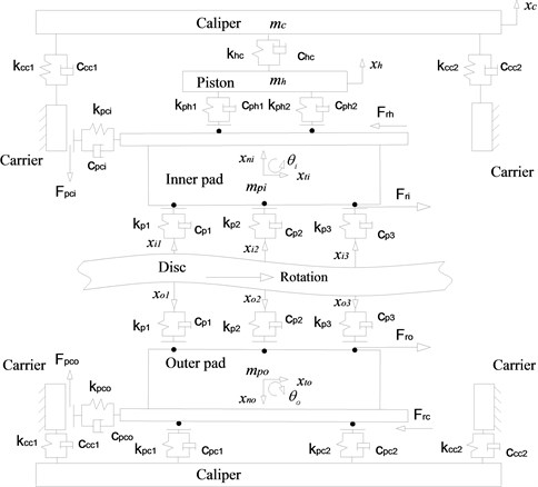
According to the concept of multi-points contact, a 8DOF model of disc brake assembly is put forward to analyze brake judder in theory, see Fig. 2. In the model, inner pad, outer pad, piston, caliper and carrier are included and carrier is fixed. Inner pad and outer pad are forced to vibrate in the normal direction of disc surface due to the initial DTV, therefore they have DOF of and respectively. and are the friction forces between disc and pad induced by disc rotation, under the action of and , inner pad and outer pad have DOF of and in the tangential direction respectively. Because of and and the uneven contact forces, inner pad and outer pad have DOF of and at the point of mass center respectively. and are the DOF of caliper and piston in the normal direction of disc surface.
There are 3 contact points between disc and pads in each side, and the contact stiffness and damping of each contact point are supposed to be equal, thus 137.4×10⁷ N/m, and 13103 Ns/m. and are the nominal contact stiffeness and damping between disc and pad. There are 2 contact points between inner pad and piston, and the contact stiffenss and damping of each point are supposed to be equal, 4×10⁸ N/m, 10 Ns/m. and are the nominal contact stiffeness and damping between inner pad and piston. There are 2 contact points between outer pad and caliper, and the contact stiffenss and damping of each point are equal too, 3.48×10⁷ N/m, 20 Ns/m. and are the nominal contact stiffeness and damping between outer pad and caliper.
Because of the friction forces of and , there are friction force between piston and inner pad and friction force between caliper and outer pad. Under the action of these friction forces, inner pad and outer pad move in the tangential direction and the pad lugs near leading edge contact with carrier. and are the contact stiffness and damping between inner pad and carrier, and and are the contact stiffness and damping between outer pad and carrier, 1.93×10⁷ N/m and 12 Ns/m. Meanwhile inner pad and outer pad vibrate in the normal direction, thus friction force exists between inner pad and carrier and friction force exists beteween outer pad and carrier.
Fig. 2A dynamic model of disc brake assembly with multi-points contact
Under the excitation from initial DTV, the differential equations of the inner pad and outer pad are shown as:
where, , and are the displacements of contact points between inner pad and disc, , and are the displacements of contact points between outer pad and disc. and are the displacements of contact points between inner pad and piston, and are the displacements of contact points between outer pad and caliper. and are the mass and inertia moment of inner pad, and and are the mass and inertia moment of outer pad. 0.48 kg and 9×10⁻⁷ kg·m2.
The differential equation of the piston is shown as:
where, and are the contact stiffness and damping between piston and caliper, and 3.48×10⁷ N/m and 6×10³ Ns/m. is mass of piston and 0.77 kg.
The differential equation of the caliper is shown as:
where, , and , are the contact stiffness and damping between caliper and carrier, and 7.5×10⁸ N/m, 10 Ns/m. and are the stiffness and damping of guide pin and seals. is mass of caliper and 2.65 kg.
In the Eqs. (1)-(4), there are some friction forces and they are shown as follows:
In the Eq. (5)-(10), is the friction coefficient between disc and pads and it will be discussed in Section 3. is the friction coefficient between inner pad and piston, is the friction coefficient between outer pad and caliper, is the friction coefficient between inner pad and carrier, is the friction coefficient between outer pad and carrier, and 0.43.
Based on the above dynamic model of disc brake assembly, brake torque and brake torque variation can be given as:
Brake pressure and brake pressure variation are given as:
In the Eq. (11)-(12), is the initial value of brake pressure, is the piston area and is the brake equivalent radius. In the model, 1.96×10⁻³ m2 and 9.57×10⁻² m.
2.2. The input model of disc brake judder
Based on the position of contact points in brake pads, the displacements of contact points can be calculated. It is supposed that the displacement of is equal with the displacment of the pad in normal direction, and it can be shown as and . The the displacements of other contact points in inner pad can be given as and . In the same way, the the displacements of other contact points in outer pad can be also given as and Therefore it can be seen that the inputs of Eq. (1)-(10) are , , in the inner side and , , in the outer side, which are related with disc thickness variation.
The initial DTV can be measured by non-contact displacement sensors, shown as Fig. 9, and it usually has the characteristics of sine function, in which the variable is disc circumferential angle . In order to express conveniently, the initial DTV is defined as . Theoretical studies [14, 15, 19] have proposed that initial DTV is the excitation of brake judder and it can be evenly divided into the outer and inner surfaces in simulations. On this basis and due to the circumferential angle between , and is 12° respectively, the inputs of contact points between disc and pads can be given as:
In Eq. (13), disc circumferential angle is related with with braking angular speed . In the braking process, can be calculated by:
where, is a quarter of a vehcile total mass and 435 kg. is the rolling radius of tyre and 0.28 m. is the initial angular speed. The rotation angle of disc in time domain is defined as , and then , and is the integer part of 360. is the braking time.
3. Semi-empirical model of friction coefficient
From Eq. (11), it can be seen that the friction coefficient between disc and pads plays an important role in brake judder analysis. In order to obtain accurate simulation results, the friction coefficient of disc brake is necessary to know and it can be measured in brake inertial dynamometer. Friction coefficient of disc brake can be calculated by , where, is brake torque, is brake hydraulic pressure, is the piston area and is the brake equivalent radius. According to experiment results of brake judder, friction coefficients of disc brake is calculated and shown in Fig. 3. From Fig. 3, it can be seen that friction coefficient increases with the decreasing braking speed of the disc, and decreases with the increasing brake pressure. In the process of braking, the disc surface temperature is less than 300°C, and friction heating usually plays little role on brake friction coefficient in this temperature range [36].
Fig. 3Friction coefficient of a disc brake
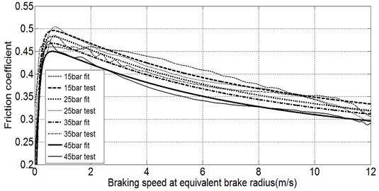
For the convenience of brake judder simulation and analysis, a semi-empirical model of brake friction coefficient is proposed using magic formula tyre model [37]. The semi-empirical model of brake friction coefficient is given as:
In the Eq. (15) is defined as the friction coefficient, and is the relative velocity between disc and pad in tangential direction. represents the peak value of friction coefficient, and represents the initial value of friction coefficient at the begining of braking. and control the limits of the range of the sine function and determine the shape of the resulting curve, and determines the slope near the end of braking, and is the angle corresponding to the slope near the end of braking. control the curveature at the peak and the horizontal position of the peak. From Fig. 3 it can be seen that factors of , , and relate with brake pressure, the values of each factor at different pressure are shown in Table 1. Therefore, the relationship between , and brake pressure can be fitted by Matlab.
Table 1The values of key factors in friciton coefficient semi-empirical model
Factor | 15 (bar) | 25 (bar) | 35 (bar) | 45 (bar) |
0.317 | 0.299 | 0.299 | 0.289 | |
0.504 | 0.484 | 0.472 | 0.459 | |
0.9 | 0.9 | 0.9 | 0.9 | |
(o) | 72.746 | 72.078 | 71.653 | 91.169 |
Based on the brake friction coefficient semi-empirical formula, the brake friction coefficient is computed on the same condition with experiment. The computed results are compared with experiment results in Fig. 3. From Fig. 3 it can be seen that the semi-emperical model of brake friction coefficient is effective and accurate, and it can be used in the simulations of brake judder and thermo-mechanical coupling.
4. Modeling and simulation of thermo-mechanical coupling considering initial DTV
4.1. FE model of thermo-mechanical coupling including initial DTV
Frictional heating results in brakes are called thermo-mechanical coupling phenomena. The theories and FE modeling of thermo-mechanical coupling are illustrated in paper [22, 38]. The general analysis progress of thermo-mechanical coupling is shown in Fig. 4. There are many studies related with thermo-mechanical coupling of disc brake, including two dimensional FE model, three dimensional axisymmetric FE model and three dimensional non-axisymmetric FE model. Some key factors including brake speed, brake pressure, friction coefficient, material properties, cooling factors are studied. Initial DTV is an important feature of disc and it plays an important role in the frictional contact between pads and disc, but it is almost neglected in the FE modeling of these studies.
Fig. 4The analysis progress of thermo-mechanical coupling of disc brake
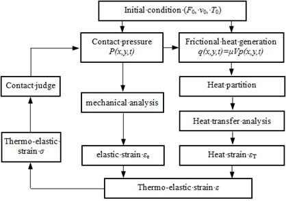
Fig. 5Brake disc FE model using a C language program code
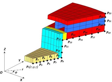
Initial DTV is no more than 100 μm and the disc thickness is usually 10-20 mm, so that initial DTV is very small relative to disc thickness and it is difficult to create initial DTV on disc surfaces in FE model. In order to solve this problem, a program code is developed in C language to create a TXT file format including the information of initial DTV, and the file can be imported in Hypermesh software to create a FE model. The file mainly contains the information of grid data and group definition. A grid data contains 4 parameters, and ID is the identification number of a grid, , , and represent the spatial location of the grid. Group definition contains many parameters. Firstly, element type should be defined, such as tetrahedron or hexahedral. Secondly, element identification number and group number are defined, and the group number means which part the element belongs to. Thirdly, grids constituted the element are defined. For example, a hexahedral element includes 6 grids, and these grids ID are assigned to the element ID.
There are so many grids and elements in disc FE model, and it is tedious to write the file manually. A program code is developed to create the file by C language. In order to develop the program code, the brake disc geometry is divided into many cylindrical parts, and the spatial location of each point in these parts can be defined in one global cylindrical coordinate. For example, a section of a disc FE model is shown in Fig. 5. The disc FE model is divided into 5 parts that have different colors in Fig. 5. The model has 16 radii in radial direction and they are controlled by points of P1 to P9 and points of P12 to P19. And it has 8 heights in direction and they are controlled by points of P9 to P12 and points of P19 to P23. Meanwhile, it has 36 circles in circumferential direction based on the distribution of ventilated fins, and each circle is divided into 3 parts with the circumferential angle of 3°, 3.5° and 3.5° respectively. The initial LRO is defined in a function or a matrix, and it is assigned to the coordinate value of disc surface grids, such as P13-P19 and P23. As illustrated in Eq. (13), the initial LRO of inner surface and outer surface has the same amplitude and opposite direction, and they constitute the initial DTV.
The main program contains 4 parts, including input part, node part, element part and output part. In the input part, the radii and the heights of the disc and the function or matrix of initial LRO of inner and outer surfaces are demanded to input. There are two subroutines in the node part. One subroutine is to create the nodes of outboard and inboard plates and the ventilated fins; the other subroutine is to create the nodes of disc hub and neck. Take the first subroutine as an example, the initial grid ID in the radius with point P13 is defined as 11000, and it is followed by a 3 layer for statements. The variable of the 1st layer for statement is the heights controlled by points P19 to point P23, and the grid ID increases 3000 in one loop, and it will be executed 5 times. The variable of the 2nd layer for statement is radii controlled by points P13 to P19, and the radius increases to the next and the grid ID increases 892 in one loop, and it will be executed 7 times. The variable of the 3rd layer for statement is the grids number, which is also the variable of the circumferential angle function. The grid ID increase 1 and the grid coordinate values of , , and are defined as the function of circumferential angle in one loop. The coordinate values of grids on the inner and outer surfaces include initial LRO and it is performed by a switch statement. The 3rd layer for statement will be executed 108 times. In the element part, there are five subroutines to create elements because the disc is divided into five parts. Take the subroutine for the outboard and inboard plates as an example, the initial element ID is defined as 1000 and the initial grid ID is 11000, and it is followed by a 2 layer for statements. The variable of the 1st layer for statement is the heights controlled by points P19 to point P23, and the grid ID increases 892 in one loop, and it will be executed 5 times. The variable of the 2nd layer for statement is the grids number. The element ID and grid ID increases 1 respectively in one loop, and the 4 grids ID on a hexahedral element upper surface are assigned to the element adjacently. The other 4 grids ID of a hexahedral element are assigned to the element in the same way. The 2nd layer for statement will be executed 108 times. The output part is to write the TXT file of Hypermesh software.
Table 2Material properties of the disc and pad
Properties | Disc | Lining | Backplate |
Density (kg/m3) | 7200 | 3600 | 7860 |
Poisson’s ratio | 0.27 | 0.25 | 0.28 |
Young’s modulus (GPa) | 120 | 0.5 | 212 |
Sepcific heat [J/(kg·°C)] | 535 | 1034 | 480 |
Thermal conductivity (W/m·°C)] | 52 | 2.06 | 31 |
Thermal expansion (1/°C) | 12 | 20 | 12 |
Because the simulation of thermo-mechanical coupling costs a lot of time, a thermo-mechanical coupling FE model only including pads and disc are built. In the present simulation, the effects of thermal radiation and wear are neglected, and the material properties of the disc and pad are temperature independent, as shown in Table 2. The friction coefficient of disc brake is defined by semi-empirical friction model. The disc rotation is controlled by a angular speed curve at the disc center and the curve is measured in brake judder experiment, which will be illustrated in Section 5.1 in detail. The heat convection coefficient between disc and surrounding environment is referred by empirical formula [39], and the heat convection between pads and surrounding environment is set in experience value. The initial angular speed is 1200 r·min-1 and decrease to 0 r·min-1, and the braking process sustains in 6.15 s. The initial pressure is 45 bar, and the initial temperature is 50°C and the initial DTV is shown in Fig. 9. Meanwhile, in order to show the influence of initial DTV to thermo-mechanical coupling characteristics, a model with smooth disc surfaces is simulated in the same condition.
4.2. Results of the thermo-mechanical coupling simulation
Due to the maximum of initial DTV is no more than 100 μm, the disc masses of the 2 FE models are equal. In order to avoid the influence of initial DTV, the thermo-mechanical coupling model without initial DTV is analyzed to validate the simulation. Firstly, the simulated results are compared with the measured results, as shown in Fig. 6. The brake judder experiment will be presented in Section 5.1. The simulated result of temperature is a little higher than measured result, and it may be caused by the neglect of disc heat radiation. The heat radiation energy accounts for 5 %-10 % of the total transferred heat energy [39]. The simulated result of surface deformation is a little smaller than the measured result and it may be caused by the neglected structure features of disc neck, such as relief groove. The surface deformation of experiment result fluctuates in the end of braking and it may be caused by the disc oscillation. Secondly, the thermo-mechanical coupling characteristics with initial DTV are compared with the results without initial DTV, including the distribution characteristics of temperature, deformation and stress in radial, circumferential and axial directions. It was found that the initial DTV changed the thermo-mechanical coupling characteristics in circumferential direction, which will be discussed in next chapters. Initial DTV didn’t change the deformation value of thermal conning and changed a little of the temperature curve in time domain due to the temperature gradient in circumferential direction, and these were not shown in the paper due to space limitations. Finally, it can be concluded that the thermo-mechanical coupling model of disc brake is correct and has a good accuracy.
Fig. 6The comparison between simulation results and experiment results
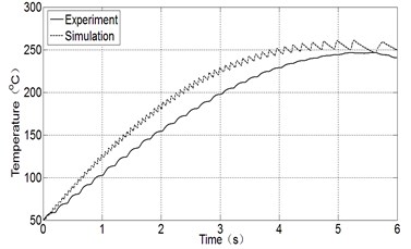
a) Temperature of disc outer surface
b) Deformation of disc inner surface
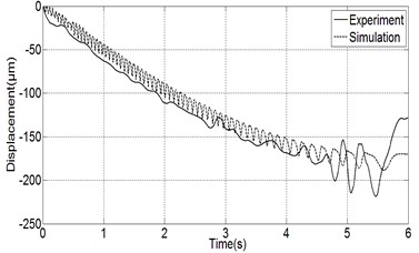
When initial DTV is considered in FE model, the thermo-mechanical coupling characteristics change seriously. Because the disc temperature distribution and deformation distribution are closely related with brake judder, these characteristics are analyzed in detail. Fig. 7 shows the temperature distribution of disc outer surface at braking time 4 s. From Fig. 7(a), it can be seen that the temperature with initial DTV is higher than the temperature without initial DTV in the annular region from radius 110 mm to radius 128 mm, and the main reason of this phenomenon is that the contact pressure in the region becomes higer due to the initial DTV and thermal warping. Meanwhile, it can be seen that the temperature distribution in circumferential dirction with initial DTV is obviously different with the result without initial DTV. Fig. 7(b) shows the temperature distribution in circumferential direction at radius 93 mm, and it can be seen that the temperature without initial DTV doesn’t have the characteristic of sine function, and the temperature with initial DTV has a characteristic of 2 order sine function as initial DTV, thus the temperature gradient in circumferential direction increases too much. In a word, initial DTV plays an important role in the temperature distribution characteristics.
Fig. 7The temperature distribution of disc outer surface
a) Spatial distribution
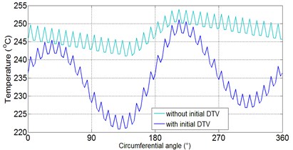
b) Circumferential distribution at radius 93 mm
Disc deformation in direction is related with temperature. The sum of outer surface deformation and inner surface deformation is the thickness deformation caused by thermo-mechanical coupling. Fig. 8 shows the distribution of thickness deformation. From Fig. 8(a), it can be seen that the thickness deformation with initial DTV is bigger than the deformation without initial DTV in the annular region from radius 110 mm to radius 128 mm, and it is samller than the deformation without initial DTV in the annular region from radius 76 mm to radius 102 mm. Meanwhile, the thickness deformation with initial DTV has a characteristic of 2 order sine function as initial DTV, but the deformation without initial DTV doesn’t have the characteristic. Fig. 8(b) shows the thickness deformation distribution in circumferential direction at radius 93 mm, and it shows that the thickness deformation gradient in circumferential direction increases too much when initial DTV is considered. Therefore, it can be included that initial DTV plays an important role in the thickness deformation characteristics.
Fig. 8The distribution of disc thickness variation caused by thermo-mechanical coupling
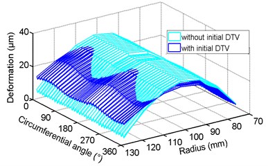
a) Spatial distribution
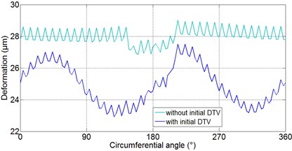
b) Circumferential distribution at radius 93 mm
4.3. Effects of thermo-mechanical coupling on the judder excitation
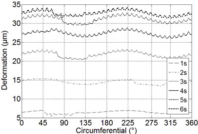
Through the analysis of thermo-mechanical coupling simulation considering initial DTV, it indicates that initial DTV plays important roles in thermo-mechanical coupling characteristics. Meanwhile, the thermo-mechanical coupling changes the disc thickness. Fig. 9 shows the initial DTV measured by non contact displacements in brake judder experiment, and Fig. 10 shows the thickness variation of braking equivalent radius caused by thermo-mechanical coupling at different braking time. From Fig. 9 and Fig. 10, it can be seen that under the effects of thermo-mechanical coupling, disc thickness with a characteristic of 2 order sine function in circumferential direction expands gradually in the process of braking. The increasing disc thickness produced by thermo-mechanical coupling is defined as , and it induces brake judder to deteriorate.
Fig. 9Initial DTV of a brake disc
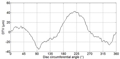
Fig. 10Thickness variation caused by thermo-mechanical coupling at different time
can be given as a function of anular speed and circumferential angle . In order to express conveniently, it is shown as a matrix , and is the sample size of braking time , is the sample size of circumferential angle . When the sample interval of braking time and circumferential angle is small enough, and are large and can represent disc thickness variation caused by thermo-mechanical coupling. In the disc FE modeling, a circumference is divided into 108 parts and 0° and 360° should be coincident, thus is 109. In the simulation of thermo-mechanical coupling, the simulation time is 6.15 s and the sample interval of exporting simulated results is 10-2 s, thus is 615. Based on this, can ben shown as a matrix [615,109]. Using the Lookup Table (2-D) block of Matlab/simulink, of every location at braking equivalent radius can be calculated at any braking time. Brake judder excitation considering thermo-mechanical coupling can be given as:
where , and is the input of inner pad considering thermo-mechanical coupling, and , and is the input of outer pad considering thermo-mechanical coupling.
5. Brake judder analysis considering thermo-mechanical coupling
5.1. Brake judder experiment
The experiment is carried out on Link NVH brake dynamometer. Brake torque and angular speed are measured by the sensors integrated in the standard dynamometer, and brake pressure is measured by oil pressure sensors integrated in the brake fluid apply system. 2 fast response thermocouples are used to measure the temperature of disc surfaces, and 6 non contact capacitive displacement sensors are used to measure the disc initial LRO and DTV and the thermal deformation. There are one thermocouple and three displacement sensors at each side of the disc, and the thermocouple and the displacement sensor at the middle position are located at the brake equivalent radius. A acceleration sensor is used to measure the vibration of brake caliper in direction. Fig. 11 shows the measurements schematic and photographs of brake judder experiment. A ventilated disc is mounted with a rigid connection to the drive shaft, and a single piston caliper is mounted with a rigid fixture.
Fig. 11Measurements in brake judder experiment
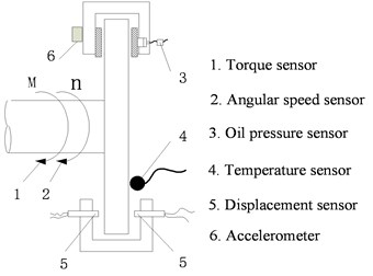
a) Measurement schematic
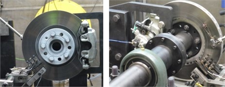
b) Photographs of experiment
The inertial of the dynamometer is 34 Kg·m2 and 2 discs are used in the experiment. The initial DTV of one disc is shown in Fig. 9, and the initial DTV of the other one is less than 5 μm, which is uesd to study the effects of initial DTV on thermo-mechanical coupling characteristics. In the experiment the flywheel is accelerated to a constant angular speed of 1200 r·min-1 by an servo motor, and a thermocouple is used to monitor the disc surface temperature. When the disc surface temperature is about 50°C, and the braking system is applied at a constant hydraulic pressure. After a few seconds, the disc is braked to stop. In the experiment, initial brake pressure has 4 levels of 15 bar, 25 bar, 35 bar and 45 bar.
5.2. Results of simulations and experiment
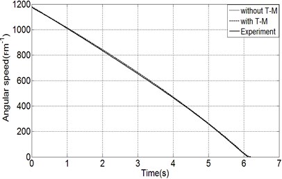
Based on the above experiment and mathematical models, the characteristics of brake judder including angular speed, acceleration of brake caliper, brake pressure and brake torque are calculated in Matlab/simulink, and the results of simulations and experiment are analyzed in detail. In order to express conveniently, without T-M represents the simulation of no considering the effects of thermo-mechanical coupling, and with T-M represents the simulation of considering the effects of thermo-mechanical coupling. Because brake judder phenomena are not evident at the end of braking, the results from 0s to 6s are focused to discuss.
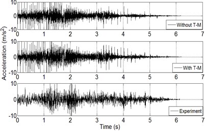
Fig. 12 shows the comparison between simulation results and experiment results in time domain. From Fig. 12(a), it can be obviously observed that the simulated and measured angular speeds have a good agreement with each other, and the effects of thermo-mechanical coupling plays little role on angular speed. For acceleration of brake caliper, the same conclusion can be obtained as angular speed from Fig. 12(b), and it may be related with the rigid fixture of caliper and the tyre and suspension are neglected in the system. However, brake pressure and brake torque considering thermo-mechanical coupling changed seriously from the results of without T-M.
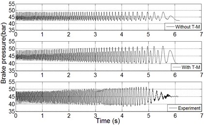
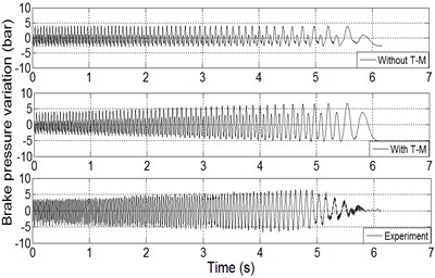
Fig. 12(c) shows the results of brake pressure. From the point of view of the trend, brake pressure fluctuates near the initial brake pressure of 45 bar, but it is flat and uniform in the simulation of without thermo-mechanical coupling, and the result increases gradually in the most braking process in the simulation of considering the effects of thermo-mechanical coupling, which has a good agreement with experiment result. From the point of view of global minimum and maximum values, brake pressure without thermo-mechanical coupling fluctuates in the range of 42.1 bar-48.9 bar, and it fluctuates in the range of 39.6 bar-51.9 bar when thermo-mechanical coupling is considered, and the experiment result is in the range of 39.9 bar-51.5 bar. In order to illustrate the fluctuation of brake pressure directly, Fig. 12(d) shows the brake pressure variation in time domain. From Fig. 12(d), it can be seen that the maximum values of BPV are 6.5 bar, 12.3 bar and 11.3 bar on the conditions of without/with thermo-mechanical coupling and experiment respectively. Therefore, it can be concluded that the effects of thermo-mechnical coupling induces BPV to increas and the brake judder simulation considering these effects has a good accuracy with experiment results.
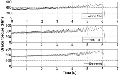
Fig. 12(e) shows the results of brake torque. From the point of view of the trend, brake torque increases in the braking process, and it is mainly caused by the characteristics of friction coefficient, and the trend terms of the three results are almost the same. However, barke torque fluctuations in the braking process are different between the two kinds of simulations. Brake torque fluctuation without thermo-mechanical coupling is flat and uniform, as shown in Fig. 12(f), but it increases gradually in the most braking process in the simulation of considering the effects of thermo-mechanical coupling, which has a good agreement with experiment result. From the point of view of global minimum and maximum values, brake torque fluctuates without thermo-mechanical coupling in the range of 464.1 Nm-800.4 Nm, and it fluctuates in the range of 463.5 Nm-854.4 Nm on the condition of with thermo-mechanical coupling, and the experiment result is in the range of 499.4 Nm-818.5 Nm. Fig. 12(f) shows the brake torque variation directly in time domain. From Fig. 12(f), it can be seen that the maximum values of BTV are 114.2 Nm, 215.8 Nm and 199.8 Nm on the conditions of without/with thermo-mechanical coupling and experiment respectively. Therefore, it can be concluded that the effects of thermo-mechnical coupling induces BTV to increase and the brake judder simulation considering these effects has a good accuracy with experiment results.
Fig. 12The comparison between simulation results and experiment results in time domain
a) Angular speed
b) Acceleration of brake caliper
c) Brake pressure
d) BPV
e) Brake torque
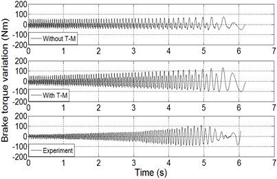
f) BTV
The simulation results are also compared with experiment results in frequency domain. BPV, BTV and acceleration of brake caliper are analyzed in method of Short Time Fourier Transform. The waterfall diagrams of the response are displayed in Fig. 13, and the abscissa is the frequency and the ordinate is the angular speed. Because the characterisitc of BPV is the approximate with BTV in frequency domain, the waterfall diagram of BPV is not shown. From Fig. 13(a), it can be seen that the frequency of BTV has a relationship of two-order with the angular speed. For example, when the angular speed is 1200 r·m-1, the associated frequecy of BTV is 40 Hz. Whether or not considering the effects of thermo-mechanical coupling, the characteristics of BPV and BTV in frequency domain consist with the experiment results, but the results of with thermo-mechanical coupling has a better agreement with experiment results. Fig. 13(b) shows the results of acceleration of brake caliper in frequency domain and the simulated results and measured result have a good agreement with each other. However, the frequecy of brake caliper acceleration doesn’t have the relaitonship of two-order with angular speed, and it is mainly caused by the rigid fixture of caliper and the tyre and suspension are neglected in the system.
Fig. 13The comparison between simulation results and experiment results in frequency domain
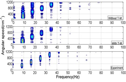
a) BTV
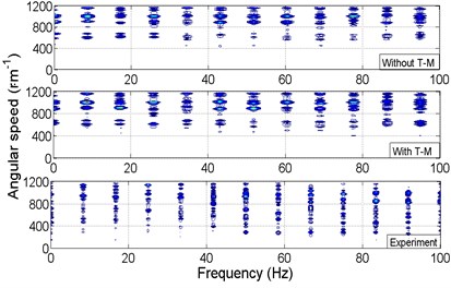
b) Acceleration of brake caliper
Through the discussion of the results, it indicates that the effects of thermo-mechanical coupling play important roles on BPV and BTV in time domain. The quantitative contributions of thermo-mechanical coupling on brake judder can be calculated by this study. For example, for the result with thermo-mechanical coupling in Fig. 12(c), most of local maximums consitute the upper envelope curve of brake pressure, and it is defined as . Most of local minimums consitute the lower envelope curve of brake pressure, and it is defined as . For the result without thermo-mechanical coupling in Fig. 12(c), the upper and lower envelope curves can be calculated and they are defined as and respectively. The contribution of thermo-mechanical coupling on brake pressure by upper envelope curves is defined as and . The contribution by lower envelope curves is defined as and The average contribution is defined as and . In the same way, the contribution of thermo-mechanical coupling on brake torque can be calculated. Fig. 14 shows the contribution of thermo-mechanical coupling on brake judder. From Fig. 14, it can be seen that the contributions on brake pressure and brake torque increase with the disc temperature in the braking process, and the average contributions on brake pressure and brake torque can reach 45 % and 50 % respectively.
Fig. 14The contributions of thermo-mechanical coupling on brake judder
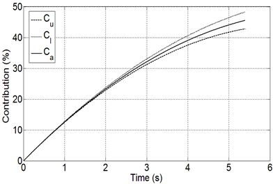
a) Brake pressure
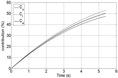
b) Brake torque
6. Conclusions
In this paper, a modeling method of brake judder is proposed to reproduce the real behaviors of brake judder in time domain, taking into account the effects of thermo-mechanical coupling in the temperature range of 100°C to 300°C. The simulation of brake judder using this method is computed to investigate the influences of thermo-mechanical coupling on brake judder.
A 8-DOF vibration model of brake caliper assembly with multi-contact points is established mathematically, and 3-DOF of pad in normal direction, tangential direction and rotational direction at the point of mass center are considered in the model. Then a semi-empirical model of friciton coefficient related with brake pressure and angular speed is proposed using magic formula tyre model, and it is validated by experiment results.
Meanwhile, a disc FE model including initial DTV is proposed using a program code developed in C language, and it is used in a thermo-mechanical coupling model which is validated by experiment results. It is found that the gradients of temperature and disc thickness deformation in circumferential direction increase too much when initial DTV is considered in modeling. On this basis, the disc thickness variation considering thermo-mechanical coupling is calculated and used as the input of brake judder vibration model.
Based on the modeling of brake judder considering thermo-mechanical coupling, the simulation results including angular speed, acceleration of brake caliper, brake pressure and brake torque are analyzed in time domain and frequency domain. From the point view of the trend, the global minimum and maximum values, the simulated brake pressure and brake torque without and with thermo-mechanical coupling are compared with the experiment results respectively, and it indicates that the simulated results considering thermo-mechanical coupling have a good agreement with experiment results. BPV and BTV increase gradually in time domain because of the effects of thermo-mechanical coupling, and the amount of increase in brake pressure and brake torque can reach 45 % and 50 % respectively in the simulation.
References
-
Jacobsson H. Aspects of disc brake judder. Proceedings of the Institution of Mechanical Engineers, Part D: Journal of Automobile Engineering, Vol. 217, Issue 6, 2003, p. 419-430.
-
Cantoni C., Cesarini R., Mastinu G., Rocca G., Sicigliano R. Brake comfort – a review. Vehicle System Dynamics, Vol. 47, Issue 8, 2009, p. 901-947.
-
Kim M., Jeong H., Yoo W. Sensitivity analysis of chassis system to improve shimmy and brake judder vibration on steering wheel. SAE Technical Paper 960734, 1996.
-
Gao X., Yu Z., Zhang L. An analysis on transmission path from brake judder to steering wheel vibration. Automotive Engineering, Vol. 28, Issue 3, 2006, p. 267-270.
-
Hussain K., Yang S. H., Day A. A study of commercial vehicle brake judder transmission using multi-body dynamic analysis. Proceedings of the Institution of Mechanical Engineers, Part K: Journal of Multi-body Dynamics, Vol. 221, Issue 2, 2007, p. 311-318.
-
Singh A., Lukianov G. Simulation process to investigate suspension sensitivity to brake judder. SAE Technical Paper 2007-01-0590, 2007.
-
Yu J., Brickner B., Nutwell B., Johnson M. Analysis of vehicle chassis transmissibility of steering shimmy and brake judder: mechanism study and virtual design of experiment. SAE Technical Paper 2007-01-2342, 2007.
-
Hwang I. J., Park G. J. Mode and design sensitivity analyses for brake judder reduction. Proceedings of the Institution of Mechanical Engineers, Part D: Journal of Automobile Engineering, Vol. 222, Issue 7, 2008, p. 1259-1272.
-
Chen S. M., Wang D. F., Zan J. M. Brake judder analysis using a car rigid-flexible coupling model. Proceedings of the Institution of Mechanical Engineers, Part D: Journal of Automobile Engineering, Vol. 226, Issue 3, 2012, p. 348-361.
-
Lee J. H., Park T. W., Jung S. P., Kim W. H. Sensitivity analysis of transfer mechanism considering dynamic characteristic of a bushing. Proceedings of the World Congress on Engineering, London, U.K., 2010.
-
Sim K. S., Lee J. H., Park T. W., Cho M. H. Vibration path analysis and optimal design of the suspension for brake judder reduction. International Journal of Automotive Technology, Vol. 14, Issue 4, 2013, p. 587-594.
-
Kim B., Song S., Kim J., Park K., Akai K. Vehicle ride comfort and brake judder dynamics analysis considering nonlinear characteristics. SAE Technical Paper 2003-01-1614, 2006.
-
Jacobsson H. Analysis of brake judder by use of amplitude functions. SAE Technical Paper 1999-01-1779, 1999.
-
Jacobsson H. Disc brake judder considering instantaneous disc thickness and spatial friction variation. Proceedings of the Institution of Mechanical Engineers, Part D: Journal of Automobile Engineering, Vol. 217, Issue 5, 2003, p. 325-342.
-
Leslie A. C. Mathematical model of brake caliper to determine brake torque variation associated with disc thickness variation (DTV) input. SAE Technical Paper 2004-01-2777, 2004.
-
Dreyer J., Drabison J., Liette J., Singh R. Effect of disc-pad contact modification on the brake judder source using a simplified elasto-kinematic model. SAE Technical Paper 2013-01-1907, 2003.
-
Kim S., Han E., Kang S., Cho S. Investigation of influential factors of a brake corner system to reduce brake torque variation. International Journal of Automotive Technology, Vol. 9, Issue 2, 2008, p. 233-247.
-
Jaeyoung K., Sungjin C. Brake dynamometer model predicting brake torque variation due to disc thickness variation. Proceedings of the Institution of Mechanical Engineers, Part D: Journal of Automobile Engineering, Vol. 221, Issue 1, 2007, p. 49-55.
-
Heckmann A., Kurzeck B., Carrarini A., Günther F., Schroeder-Bodenstein K. Influences on nonlinear judder vibrations of railway brakes. Vehicle System Dynamics, Vol. 48, Issue 6, 2010, p. 659-674.
-
Sen O. T., Singh R. Improved mathematical models of vehicle brake judder and experimental observations. Inter-noise, New York, USA, 2012.
-
Duan C., Singh R. Analysis of the vehicle brake judder problem by employing a simplified source-path-receiver model. Proceedings of the Institution of Mechanical Engineers, Part D: Journal of Automobile Engineering, Vol. 225, Issue 2, 2011, p. 141-149.
-
Yevtushenko A. A., Grzes P. The FEM-Modeling of the frictional heating phenomenon in the pad/disc tribosystem (A Review). Numerical Heat Transfer, Part A: Applications, Vol. 58, Issue 3, 2010, p. 207-226.
-
Stringham W., Jank P., Pfeifer J., Wang A. Brake Roughness – disc brake torque variation, rotor distortion and vehicle response. SAE Technical Paper 930803, 1993.
-
Little E., Kao T., Ferdani P., Hodges T. A Dynamometer Investigation of Thermal Judder. SAE Technical Paper 982252, 1992.
-
Kao T. K., Richmond J. W., Douarre A. Brake disc hot spotting and thermal judder: an experimental and finite element study. International Journal of Vehicle Design, Vol. 23, Issue 3, 2000, p. 276-296.
-
Altuzarra O., Amezua E., Aviles R., Hernandez A. Judder vibration in disc brakes excited by thermoelastic instability. Engineering Computations, Vol. 19, Issue 3, 2002, p. 411-430.
-
Heckmann A. A brake model with thermoelastic disc for the analysis of vehicle judder vibrations. Vehicle System Dynamics, Vol. 44, Issue 1, 2006, p. 360-367.
-
Jung S. P., Park T. W., Chai J. B., Chung W. S. Thermo-mechanical finite element analysis of hot judder phenomenon of a ventilated disc brake system. International Journal of Precision Engineering and Manufacturing, Vol. 12, Issue 5, 2011, p. 821-828.
-
Barber J. R. Thermoelastic Instabilities in the sliding of comforming solids. Proceedings of the Royal Society of London, A: Mathematical and Physical Sciences, Vol. 312, Issue 1510, 1969, p. 381-394.
-
Lee K., Barber J. R. Frictionally excited thermoelastic instability in automotive disk brakes. Journal of Tribology, Vol. 115, Issue 4, 1993, p. 607-614.
-
Panier S., Dufrenoy P., Brunel J. F., Weichert D. Progressive waviness distortion: A new approach of hot spotting in disc brakes. Journal of Thermal Stresses, Vol. 28, Issue 1, 2005, p. 47-62.
-
Anderson A. E., Knapp R. A. Hot spotting in automotive friction systems. Wear, Vol. 135, Issue 2, 1990, p. 319-337.
-
Abdelhamid M. K., Blaschke P., Wang W. A., Yang S. An overview of brake noise and vibration problems. Proceedings of IMAC-XIX: A Conference on Structural Dynamics, Kissimmee, FL, United states, 2001, p. 57-63.
-
Fieldhouse J., Beveridge C. An Experimental Investigation of Hot Judder. SAE Technical Paper 2001-01-3135, 2001.
-
Bryant D., Fieldhouse J., Crampton A., Talbot C., Layfield J. Thermal brake judder investigations using a high speed dynamometer. SAE Technical Paper 2008-01-0818, 2008.
-
Ahmed I., Leung P., Datta P. Experimental Investigations of Disc Brake Friction. SAE Technical Paper 2000-01-2778, 2000.
-
Hans Pacejka Tyre and Vehicle Dynamics. Butterworth Heinemann, 2012.
-
Bogdanovich P., Tkachuk D. Thermal and thermomechanical phenomena in sliding contact. Journal of Friction and Wear, Vol. 30, Issue 3, 2009, p. 153-163.
-
Rudolf Limpert Analysis and design of automotive brake systems. The US Army Material Development and Readiness Command, 1976.
About this article

The authors gratefully acknowledge the support provided by China Postdoctoral Science Foundation (No. 2013M531208) and the National Natural Science Foundation of China (No. 51175380).
