Abstract
Recently, a coil gun was brought to the attention of engineering community as electromagnetic alternative to the chemical launchers. Various studies were performed on coil gun systems focused on achieving the high muzzle velocity in military applications and for satellite launching. Most of these studies focused on improvement of muzzle velocity via increase in the size of the coil gun. Present paper describes the process of design optimization where the size of the coli gun system is restricted. The design of experiment approach utilizes the orthogonal array table that reduces the required number of experiments. The design of experiment is carried out with a commercial PIAnO tool, where the finite element analysis is performed at each experimental point. Then, Kriging model is created to achieve accurate approximation in problems of many design variables or strongly nonlinear model. The coil gun is optimally designed using an evolutionary algorithm (EA) as optimization technique. In order to verify the improvement of muzzle velocity by optimal design, the prototypes of coil gun system are manufactured and the experiments to launch the projectile are performed.
1. Introduction
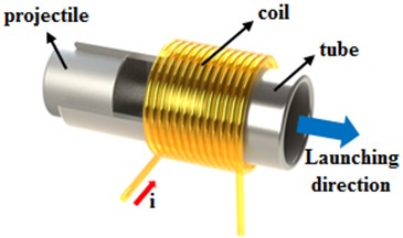
While the conventional launching system utilizing the chemical energy of the fuel has high cost and negative environmental impact, electromagnetic launching (EML) system present a viable projectile propulsion alternative with reasonably low cost and minimal environmental drawbacks (such as production of carbon dioxide). A coil gun system which is the among the most advanced EML systems, propels the projectile by electromagnetic force caused by Fleming’s right hand rule when the electric current energizes the electromagnetic solenoid coils. That is, the electromagnetic force of the coils attracts and launches the projectile [1]. Fig. 1 illustrates the schematic and operational principles of the coil gun system.
Fig. 1Schematic of coil gun system
Polytechnic Institute of New York University in the United States proposed launching method that uses LIL (Linear Induction Launcher), a type of coil gun, to reduce launching costs of micro-and nano-satellites. Design specification is to accelerate the payload of 10 kg at 30,000 g and to have the muzzle velocity of 7 km/s [2]. Sandia National Laboratories in the United States has been developing the EML techniques of low-and high-muzzle velocity using coil gun since 1980 s. These have conducted the task to develop EML accelerating as 1 km/s of 0.23 kg and 335 m/s of 5 kg [3]. VN Bondaletov of the Soviet Union driven the projectile of 1 g at a muzzle velocity of 4.9 km/s by applying a voltage of 45 kV with single stage coil gun system in the 1978 [4]. In addition, many studies of coil gun projectile launching systems are underway in the Japan and the United Kingdom.
Most of studies of coil gun system have focused on achieving high muzzle velocity because the coil gun system is mainly employed in military weapon systems and in space launching. The larger coil gun can provide higher muzzle velocity of projectile, but it also increases the required space and increases costs of the system installation, operation, maintenance, and repair.
In this paper, we performed the design optimization of the coil gun parameters to maximize the muzzle velocity while preserving the restricted size of the coil gun. Design variables are the number of axial turns of electromagnetic coil , the number of radial turns of electromagnetic coil , the initial distance between the projectile and the coil , the inner radius of electromagnetic coil , and the length of the projectile . These design variables are independent of each other but these are nonlinearly related to the magnetic force that determines the muzzle velocity. We performed optimization using the commercial optimization software PIAnO (Process Integration, Automation, and Optimization) Ver. 3.5 (PIDO-TECH). Five design variables are selected and an orthogonal design array is constructed. The analytical modeling is difficult to implement due to nonlinearity of the functional dependence of the muzzle velocity on the parameters listed above. Accordingly, finite element analysis (FEA) is performed utilizing the commercial electromagnetic analysis software MAXWELL. Subsequently, these analytical results are imported into the PIAnO and Kriging model is created to generate an accurate solution approximation of the non-linear model with many design variables. Finally, the coil gun is optimally designed using an optimization approach of the evolutionary algorithm (EA) [5-6].
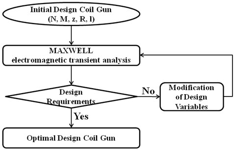
Fig. 2 shows the process of optimal design undertaken in the presented study.
Fig. 2Flow chart of the optimization
2. Optimal design of the coil gun
2.1. Coil gun system
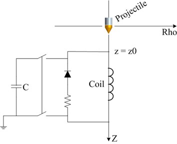
Coil gun system propels the projectile by electromagnetic force caused by Fleming’s right hand rule when the electric current energizes the electromagnetic solenoid coils. The schematic diagram of electric circuit for coil gun launching system is shown in Fig. 3. The electromagnetic coil is energized by discharging of a capacitor. The electromagnetic force of the energized coils attracts the projectile. If the electromagnetic coil is still energized after the projectile passes the longitudinal center of the electromagnetic coil windings, the magnetic force of the coils pulls the projectile in the direction opposite to the launching direction, and the projectile is decelerated. This effect is called “suck back”. To prevent this, the electric current on the electromagnetic coils must be cut off just before the projectile passes the longitudinal center of the coil windings [7].
Fig. 3Schematic diagram of electric circuit for the coil gun launching system
2.2. Definition of the design problem
2.2.1. Design requirements
The muzzle velocity of the coil gun system is proportional to the value of the maximum electric current flowing through the electromagnetic coil. However, there exists the maximum allowable value of the electric current exceeding which temperature will rise above the melting point of the coil material. The current limit value is calculated by Onderdonk’s Eq. (1):
where : fusing current in amperes, : wire area in circular mils, : melting time in seconds, : melting temperature of wire [°C], : ambient temperature [°C].
In this design, the AWG 12 commercial coil is utilized. Table 1 shows specification for the coil material [8].
Table 1Specification for AWG 12 coil material
[C] | 125 |
[°C] | 25 |
[circ. mils] | 6200 |
[ms] | 12 |
The maximum value of electric current of AWG 12 at the melting point comes to be 3700 A, but safety margin is utilized to keep the allowable current below 3000 A.
If input voltage used in this design is 200 V, the resistance of the coil can be expressed by Eq. (2) and it is summarized by Eq. (3). The procedure for calculating the coil resistance is outlined in the Eq. (4) through Eq. (7):
The number of electromagnetic coil winding turns is calculated by Eq. (8):
The mass of projectile which is one of the important factors that affects the muzzle velocity is constrained to be less than 50 gram:
When the air gap between inner radius of electromagnetic coil and the outer surface of the projectile is, the radius of the projectile, can be expressed as:
2.2.2. Design variables
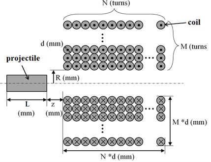
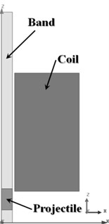
Variables in this optimized design include the number of axial direction-winding turns of electromagnetic coil, the number of radial direction-winding turns of electro-magnetic coil, the initial distance between the projectile and the electromagnetic coil, the inner radius of the electromagnetic coil and the length of the projectile as shown in Fig. 4. The initial values, lower limit and upper limit of the design variables are summarized in Table 2.
Fig. 4The diagram identifying the variables in the optimization procedure for coil gun design
Lower limit, upper limit and initial value of design variables are selected based on the design values from our preliminary study. The design problem formulation is presented as Eq. (13):
Table 2Selected lower limit, upper limit and initial value of the design variables
Design variables | Lower limit | Initial value | Upper limit | ||
Number of axial turns of coil [turns] | 1 | 11 | 20 | ||
Number of radial turns of coil [turns] | 1 | 9 | 20 | ||
Interval of projectile and coil [mm] | 5 | 5 | 30 | ||
Inner radius of electromagnetic coil [mm] | 5 | 5 | 30 | ||
Length of projectile [mm] | 4 | 10 | 80 | ||
2.3. Design of experiments and simulation
In this paper, we design experiment by considering the number of design variables, the number of levels and the orthogonality of the design matrix. In order to analyze data effectively, the orthogonal array table is created [9]. We used of orthogonal array table provided by PIAnO tools. This indicates respectively, 32 experiments, 4 levels, and columns. The number of experiments can be obtained the Eq. (14):
where the number of experiments = 1.5, : the number of design variables, : the number of saturated points.
Based on the orthogonal array, we selected the coil guns of 32 types and measured the muzzle velocity through electromagnetic analysis for each model. Finite element analysis (FEA) is performed utilizing the commercial electromagnetic analysis software MAXWELL. Fig. 5 shows 2D axisymmetric model of coil gun and projectile and plot of magnetic intensity distribution respectively.
Fig. 5a) 2D axisymmetric model and b) magnetic intensity distribution plot
a)
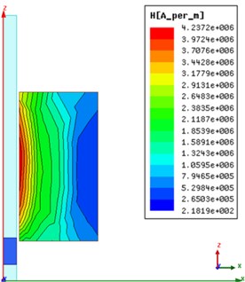
b)
2.4. Meta-model
Meta-model approximates the relationship between the value of a variable and the response value of the analytical model within all regions or the regions of interest. In this paper, we select Kriging model, one of the meta-models provided by PIAnO tools. The Kriging is a method for predicting the value in order to determine the characteristic value at a point of interest.
After placing in the PIAnO the simulation analysis results from the experimental results of 32 models, Kriging model can be created using the approximation method provided by PIAnO [10].
2.5. Result
The obtained results, the optimal design satisfied the constraints and the muzzle velocity of optimal design compared with the initial design increases by 30 %. However, the optimal design results can be changed based on using the metamodel instead of the actual analytical model in this research. The accuracy of the optimization results should be verified by actual analysis using MAXWELL. To do this, the Kriging model results ‘Opt_meta’ of the optimal design variables and the analysis results from MAXWELL ‘Opt_exact’ were compared as shown in Fig. 6. The error of ‘Opt_meta’ and ‘Opt_exact’ is about 6 %. Therefore, we confirmed the high accuracy of the Kriging model’s prediction. The initial and optimal values comparison of the design variables are summarized in Table 3.
Fig. 6The comparison of the initial model, meta model and optimal model
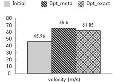
Table 3Comparison of the initial values and the optimal values for the design variables
Design variables | Lower limit | Initial value | Optimal value | Upper limit | |
(turns) | 1 | 11 | 12 | 20 | |
(turns) | 1 | 9 | 6 | 20 | |
(mm) | 5 | 5 | 13 | 30 | |
(mm) | 5 | 5 | 5 | 30 | |
(mm) | 4 | 10 | 20 | 80 | |
2.6. Experiment
To verify the result of optimization, we manufactured the prototype of coil gun system as shown in Fig. 7. Fig. 8 and Fig. 9 show the experiment setup that includes the power supply for inputting current to the solenoid coil and the measuring instruments. Once the electric current is applied to the coil by discharging the capacitor, the projectile is launched. The CCD (Charge Coupled Device) camera recorded the motion of projectile and the displacement data of projectile was obtained for each millisecond.
Fig. 10 shows the photos of the moving projectile captured by the CCD camera. Based on the position at each time, the velocity of projectile can be calculated. The velocity of the projectile launched with the coil gun of the initial design is 30.0 m/s and that of the projectile ejected from the optimized coil gun is 35.74 m/s.
Fig. 7The prototype of the coil gun system
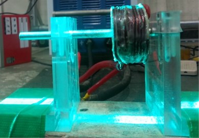
Fig. 8Schematic of the experiment
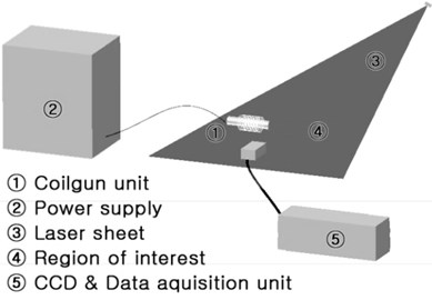
Fig. 9The experimental setup
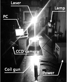
Fig. 10The photos of the moving projectile captured at different time moments

a) 1.039 sec

b)1.043 sec

c) 1.048 sec
3. Conclusion
1) The problem studied was that of the coil gun design optimization to maximize the muzzle velocity of projectile.
2) The muzzle velocities of 32 type models are calculated by electromagnetic finite element analysis.
3) The optimization process is performed through PIAnO tools. The orthogonal array, Kriging model, Evolutionary algorithms (EA) provided by PIAnO tools are used as design of experiment, meta-model and optimization techniques respectively.
4) The muzzle velocity of optimal design increases by 30 % as compared with the initial design.
5) The accuracy of the meta-model is 94.3 %.
6) In order to verify the optimal design, the prototypes of coil gun system were manufactured and projectile launching experiments were performed.
7) The difference in the results between the FE simulation prediction and the experimental data is caused mainly by the mechanical friction between the projectile and the flyway tube.
References
-
Kim Seog-Whan, Jung Hyun-Kyo, Hahn Song-Yop An Optimal Design of Capacitor-Driven Coilgun. Deptment of Electrical and Computer Engineering, Seoul National University, South Korea, (in Korean).
-
Kim Ki-Bong, Zabar Zivan, Levi Enrico, Birenbaum Leo In-bore projectile dynamics in the linear induction launcher (LIL). 1. Oscillations. IEEE Transactions on Magnetics, Vol. 31, Issue 1, 1995, p. 484-488.
-
Burgess T. J., Cowan M. Multistage induction mass accelerator. IEEE Transactions on Magnetics, Vol. 20, Issue 2, 1984, p. 235-238.
-
Haghmaram R., Shoulaie A. Study of traveling wave tubular linear induction motors. International Conference on Power System Technology, 2004, p. 288-293.
-
Choi J. S. General use PIDO solution, PIAnO. The Korean Society of Mechanical Engineers, Vol. 52, Issue 2, 2012, p. 12-13, (in Korean).
-
Hedayat A. S., Sloane N. J. A., Stufken J. Orthogonal Arrays: Theory and Applications. Springer Series in Statistics, 1999.
-
Lee Su-Jeong, Kim Ji-Hun, Kim Jin Ho Coil gun electromagnetic launcher (EML) system with multi-stage electromagnetic coils. Journal of Magnetics, Vol. 18, Issue 4, 2013, p. 481-486.
-
Lux Jim High Voltage Fuses. http://home.earthlink.net/~jimlux/hv/fuses.htm.
-
Lee Ki-Bum, Park Chang-Hyun, Kim Jin-Ho Optimal design of one-folded leaf spring with high fatigue life applied to horizontally vibrating linear actuator in smart phone. Advances in Mechanical Engineering, Vol. 2014, 2014, p. 545126.
-
Park Chang-Hyun, Lee Jun-Hee, Jeong Jae-Hyuk, Choi Dong-Hoon Design optimization of a laser printer cleaning blade for minimizing permanent set. Structural and Multidisciplinary Optimization, Vol. 49, 2014, p. 131-145.
About this article

