Abstract
A dynamic model of ball bearing-offset disk rotor system with whirling-swing coupling vibration is presented, in which the rotor disk offset position and the swing vibration of disk are concerned. In the model of ball bearing, the bearing radial clearance, nonlinear Hertzian contact force and the varying compliance (VC) vibration are considered. Numerical methods are used to obtain the nonlinear dynamic response of the system under different disk offset values for considering the disk swing vibration or not. Effects of bearing radial clearance variation on the dynamic performance of the system under different rotor offset values are investigated. It is shown that the nonlinear dynamic of the offset disk rotor system enhances obviously when rotor disk swing vibration is considered. As rotor disk offset increasing, the sensitivity of critical speed to variation of the bearing radial clearance improves.
1. Introduction
The vibration analysis of a ball bearing rotor system is becoming more important as demands on running accuracy are increased. In order to meet the design requirements of ball bearings rotor system with high speed and high precision, growing interest is devoted to the rotor disk offset position, disk swing and the variation of bearing radial clearance. In general, the ball bearing rotor system displays nonlinear behavior due to nonlinear Hertzian contact force and bearing radial clearance with high-speed unbalanced rotor. The most fundamental cause of ball bearing vibration is the periodic variation of assembly stiffness that arises as the cage rotates [1, 2]. Nowadays, the dynamic responses of a symmetric rotor supported on ball bearings have been studied extensively, however, the dynamic model of a offset disk rotor supported on ball bearings is still very immature, and the related researches of the disk swing vibration that caused by rotor offset are very few [3-5].
Although the model of ball bearings is almost perfect, it is not coupled well with the rotor vibration, and many studies have not considered the rotor offset and the disk swing vibration which are the main cause of the whirling-swing coupling vibration of the offset rotor system. The most important step in the process of ball bearing rotor system modeling is to establish the analysis model of ball bearings. The effects of VC vibrations were first studied by Perret [6] as a static running accuracy problem. He suggested that an increase in number of balls in a bearing reduces its untoward effects. Fukata et al. [7] first took up the study of ball passage vibrations and the nonlinear dynamic response for the ball bearing supporting a balanced horizontal symmetric rotor with a constant vertical force. Harsha et al. [4] have analyzed the nonlinear behavior of ball bearing due to number of balls and preload effect, and the nonlinear dynamic response is found to be associated with the ball passage frequency.
In the above mentioned studies, main attentions have been paid to the ball bearing modeling and the dynamic properties analysis according to simple bearing-rotor models. De Mul et al. [8] presented a five-degree-of-freedom (5DOF) model for the calculation of the equilibrium and associated load distribution in ball bearings. Yamauchi [9] developed a numerical harmonic balance method using the FFT algorithm for multiple degree of freedom rotor systems.
With respect to the above, more theoretical investigation should focus on the effect of rotor disk offset and disk swing vibration on the dynamic of ball bearing-rotor system. In this paper, a new dynamic model with eight-degree-of-freedom (8DOF) of an offset disk rotor system supported on ball bearings is set up by introducing disk offset parameters. The numerical integration methods are used to solve the nonlinear differential equations. The system dynamic responses under different disk offset position are compared with each other for considering the disk swing vibration or not.
2. Modeling of the ball bearing-offset disk rotor system
Considering the gyroscopic effect caused by the rotor disk offset and the nonlinear force of ball bearing, the main model parameters of the ball bearings-offset disk rotor system are shown in Fig. 1, they are the rotor shaft length (), the shaft diameter (), the disk mass (), the moment of inertia of the disk towards its shaft (), the moment of inertia of the disk towards its diameter (), the mass eccentricity of the disk (), the gravity of the disk (), the concentrated mass of the ball bearing (), and the concentrated mass of the ball bearing (). Assuming the distance from the disk to the left end bearing of the rotor is , which is defined as the offset value, and 2 means a symmetric rotor.
Fig. 1Dynamic model of ball bearing-offset disk rotor system
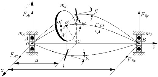
Fig. 2Schematic of Euler angle
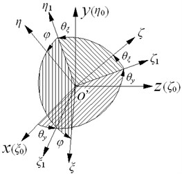
The rectangular coordinate system is established, its origin is the static equilibrium position of the left ball bearing , the axial of the shaft is axis, the vertical direction is axis, and the horizontal direction is axis. The coordinates of ball bearing and are (, ) and (, ), respectively. The coordinate of the centroid of the disk is (, ), and the mass center of the disk is . Considering the bending of the shaft, the pivot angle between the disk axis and the connection line between and is , the swing angle of the disk towards -axis and -axis are and , respectively. Assuming the angular velocity of rotation of the rotor is , the whirling angular velocity is , the gyroscopic moment of the disk is given as [10]:
The disk swing angles towards are represented by , and , which are shown in Fig. 2. the angular velocity of rotation of the rotor can also be expressed as , thus , if the angle and are very small, then , , . The total kinetic energy of the disk and the bearings at the both ends can be obtained as:
Ignoring the torsional deformation of the shaft, the generalized coordinates is defined as:
The potential energy for the rotor shaft is obtained as:
where:
is the relationship matrix of the disk displacement, the swing angle and the coordinate position of the ball bearings, is the stiffness matrix of the shaft for rigid supporting, which can be expressed as:
where is the flexibility matrix of the shaft, it can be obtained according to the material mechanics:
where is the elastic modulus, is moment of inertia of the shaft cross-section.
The disk dissipation energy in plane is obtained as:
where , is the damping matrix of the disk.
The total dissipation energy of the disk and bearings at both ends are expressed as:
where is the disk dissipation energy in the plane, which is similar to , is the bearing damping in the and directions. There are 8 degrees of freedom in the steady state equation of the ball bearing-offset rotor system, the whirling-swing coupling equations of the rotor system with damping can be expressed by Lagrange equations as:
where is the mass matrix:
and is the stiffness matrix, is the gyroscopic matrix:
and is the damping matrix, is the block matrix:
and is the imbalance force vector of rotor, is the nonlinear contact force vector of bearing, and is the gravity vector of the disk.
The dynamic model of ball bearing is shown in Fig. 3. In this model, the inner race of the bearing is assumed to have two degrees of freedom. The contact forces are summed over each of the ball elements to give overall forces on the shaft and bearing housing. The bearing parameters are determined as: the outer race radius is , the inner race radius is , the internal radial clearance is , the number of ball elements is , the angular velocity of rotation of the outer race is , the angular velocity of rotation of the inner race is , and the angular velocity of rotation of the cage is .
Fig. 3Dynamic model of ball bearing
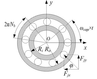
According to the movement relationship of ball bearings, 0, . The angular velocity of rotation of the cage is given by [11]:
Assuming is the angular position of the th ball element, it can be obtained as:
where, 1, 2, 3,…, , is the initial angular position of the ball element, taking 0.
The overall contact deformation of the th ball element is given by:
Neglecting the inertia of ball element, the contact forces of the inner and outer race can be combined with an overall contact stiffness. According to the nonlinear Hertzian contact theory, the nonlinear contact force between the ball element and race can be given by:
where is the Hertzian contact stiffness between the ball elements and the race, is the correlation coefficient related to the type of contact, which taking 3/2 for point contact, and 10/9 for line contact. Considering the non-negative characteristic of the contact force, 0 means no contact force, 0 means contact force generation. Considering the position of each ball element, the restoring forces of the ball bearings can be obtained:
where, indicates Heaviside function, which is defined as:
3. Analysis on whirling-swing coupling vibration of the system
The main parameters of the rotor system are determined in Table 1.
Table 1The main parameters of the rotor system
Mass of disk () | 34.6 kg |
Mass of ball bearing A () | 2 kg |
Mass of ball bearing B () | 2 kg |
Mass eccentricity of disk () | 30 μm |
Moment inertia of the disk towards axis () | 0.7 kg·m2 |
Moment inertia of the disk towards diameter () | 0.35 kg·m2 |
Length of shaft () | 500 mm |
Diameter of shaft () | 40 mm |
Young’s modulus () | 2.09×10⁵ MPa |
Disk damping () | 2100 N·s/m |
Bearing damping () | 1050 N·s/m |
The parameters of ball bearing are selected according to the reference [12] in this paper, and its parameters are listed in Table 2.
Table 2The main parameters of the ball bearings
Radius of the outer race () | 63.9 mm |
Radius of the inter race () | 40.1 mm |
Number of ball elements () | 9 |
Contact stiffness coefficient () | 13.34×10⁹ N/m3/2 |
Bearing radial clearance () | 10 μm |
For the strong nonlinear of the ball bearing-offset disk rotor system, so the classic perturbation methods can not be applied directly, and the numerical methods for solving the system dynamic response are more effective. In this paper, the fourth-order Runge-Kutta method is adopted for variable step integration in Eq. (9) to obtain the displacement and velocity of the disk. The longer the time to reach steady state vibrations, the longer CPU time needed, and the more expensive the computation. In order to eliminate the effect of transient vibrations, a total of 600 cycles are calculated, the unsteady solutions are discarded, and the steady-state solution of the last 100 cycles are extracted, and the peak steady state amplitude of vibration can be measured. The dynamics responses of the system are calculated for 0-2500 rad/s. When the disk swing vibration is not considered, , , thus the degrees of freedom of the system are reduced to 6 DOF. Dynamics response of the system are compared for the rotor offset value 2, 3, 5 and 7.
3.1. The effect of rotor disk offset on the response of the system
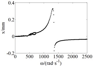
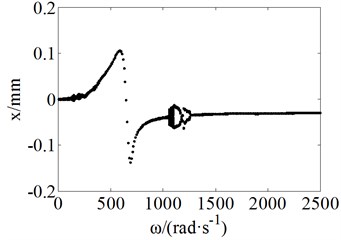
Rotor responses are obtained by numerical integration, and the effects of rotating speed and bearing clearance on system responses are studied under different disk offset. The bifurcation plots, the phase plots, the frequency spectra, and the Poincaré maps are used to analyze the characteristics of bifurcation and chaos of system responses. Fig. 4 shows the bifurcation plots of the displacement as angular velocity under different rotor offset value when the swing vibrations of the disk are not considered.
Fig. 4Bifurcation plots not considering swing vibrations
a)3
b)5
c)7
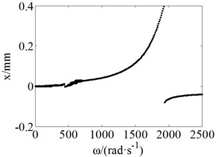
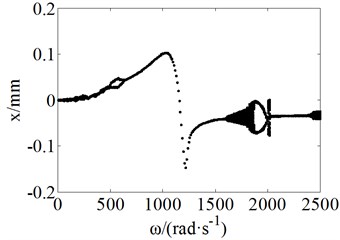
Fig. 5 shows the bifurcation plots when the swing vibrations of the disk are considered.
Fig. 5Bifurcation plots by considering swing vibration
a)3
b)5
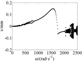
c)7
Figs. 4-5 indicate that when angular velocity ω is near the first-order critical speed of the rotor system, the response amplitudes become very great, and the VC vibration is relatively weak, the system is period 1 motion. By comparison, it can be found that the nonlinear dynamics of the rotor system enhance significantly for considering the swing vibration of the disk, as the rotor disk offset increasing (offset value a decreases), the nonlinear dynamics of the system become more obvious at high angular velocity. Table 3 shows the response status of the system for 7 whether considering the disk swing vibration or not.
Table 3Response of the rotor system
Not considering the disk swing vibration | Considering the disk swing vibration | ||
(rad/s) | Response status | (rad/s) | Response status |
5-770 | Quasic-periodic/Chaos | 5-535 | Quasic-periodic / Chaos |
770-1885 | Period 1 motion | 535-805 | Period 2 motion |
1885 | Jump | 805-1950 | Period 1 motion |
1885-2500 | Period 1 motion | 1950-2025 | Period 2 motion |
– | – | 2025-2070 | Period 3 motion |
– | – | 2070-2225 | Quasic-periodic / Chaos |
– | – | 2225-2270 | Period 5 motion |
– | – | 2270-2500 | Quasic-periodic / Chaos |
Fig. 6 shows the variation of the disk swing angle as for the offset value 2 and 7 by considering the swing vibration. Affected by the VC vibration of the ball bearing, the disk shimmy slightly even for the symmetric rotor system (2), and the variations of the disk swing angle are similar to the change of the displacement of the disk.
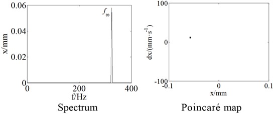
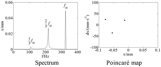
Figs. 7(a), (b) and (c) show the phase plots and Poincaré maps under the offset values 7 for 780 rad/s, 2200 rad/s and 2255 rad/s by considering the swing vibration of the disk, and the motions of the system are respectively periodic 2, quasi-periodic and periodic 5.
Fig. 6Bifurcation plots of the disk swing angle α
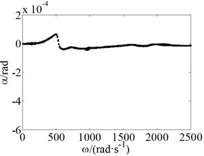
a)2
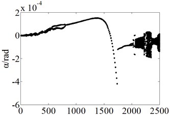
b)7
Fig. 7The phase plane plots and Poincaré maps for a=l/7
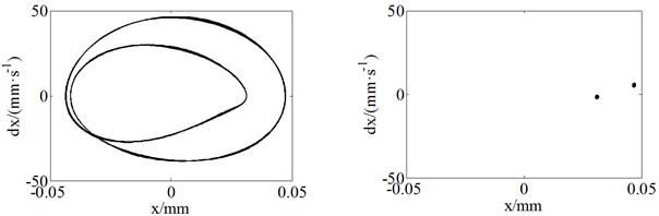
a) 780 rad/s
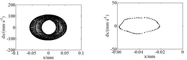
b) 2200 rad/s
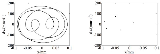
c) 2255 rad/s
3.2. The effect of rotor disk offset on the natural frequency of the system
The frequencies of the rotor system consist of two fundamental frequency components, one of the frequencies is the rotational frequency of the rotor, which can be expressed as:
Another fundamental frequency component is the VC vibration frequency of the ball bearing, which is produced by the variation of bearing radial stiffness when the ball elements run through the load area, and the VC frequency can be given by:
Obviously, the variable depends on the dimensions of the bearings, in this paper 3.47.
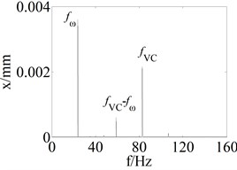
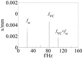
Figs. 8(a) and (b) show the response of the disk in the direction for 7 and 30 rad/s. As can be seen, due to the low angular velocity of the rotor, the frequencies of the system are mainly the VC frequency components and its harmonics.
Fig. 8The rotor response for a=l/7 and ω= 30 rad/s
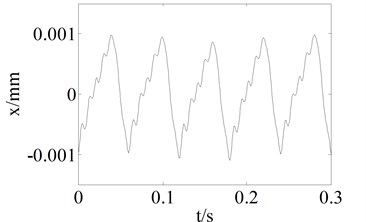
a) Time-domain waveform
b) Spectrum
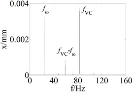
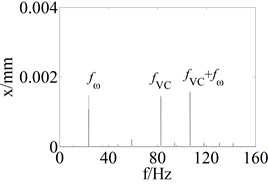
Figs. 9(a) and (b) show the disk response for 7 and 2040 rad/s for considering the disk swing vibration or not. As the angular velocity increasing, the unbalanced vibration of the shaft is more obvious than the VC vibration of the bearings, and the harmonic components of the rotational frequency of the rotor appear for considering the swing vibration of the disk, and the period 3 motion of the rotor system is mainly caused by the swing vibration of the disk.
Fig. 9The rotor response for a=l/7 and ω= 2040 rad/s
a) Not considering the swing vibration of the disk
b) Considering the swing vibration of the disk
Fig. 10 shows the spectrums of the rotor system under different rotor offset value (2, 3, 5, 7 and 9) for 150 rad/s, respectively.
Fig. 10The spectrum under different disk offset value
a)2
b)3
c)5
d)7
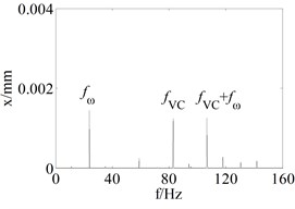
e)9
As can be seen from Fig. 10, the frequencies of the rotor system contain rotational frequency (), VC frequency () and the combination frequencies under different rotor disk offset. As the rotor disk offset increasing (value decreases), the amplitude of rotational frequency decreases gradually. The difference frequencies between the VC frequency and the rotational frequency disappear, and the sum frequencies of the VC frequency and the rotational frequency emergence.
3.3. The effect of bearing radial clearance on the whirling-swing coupling vibration.
The effects of bearing radial clearance on the whirling-swing coupling vibration of the offset rotor system are analyzed for the bearing radial clearance varing from –10 μm to 40 μm. Fig. 11 shows the critical speed of the rotor varies as increasing under different rotor disk offset.
Fig. 11The critical speed variation as μ0 increasing
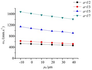
It can be seen from Fig. 11, as increasing, the critical speeds of the system show a linear decreasing trend, the decreasing rate for different rotor disk offset can be obtained in Table 4.
It is found from Table 4 that as the rotor disk offset increasing (value decreases), the critical speeds of the rotor decrease more obviously, which indicates that the sensitivity of critical speed to bearing clearance variation improves when the rotor disk offset increases. Fig. 12 shows the variation of the resonance peaks of the rotor and the maximum swing angle of the disk as under different rotor offset.
Fig. 12The variation of the resonance peak and maximum swing angle
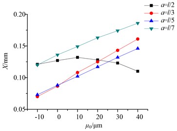
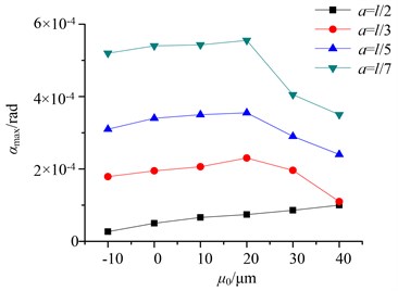
Table 4The decreasing rate of the critical speed
Offset value | Decreasing rate/(rad·s-1/μm) |
2 | 1.4 |
3 | 2.1 |
5 | 4.6 |
7 | 5.3 |
As can be seen from Fig. 12, the resonance peaks are not monotonic as the bearing radial clearance increasing for the symmetric rotor system (2), but increasing at first then decreasing, and the maximum swing angle tends to increase. The resonance peaks show linear increase as the bearing radial clearance increasing for the offset rotor system (3, 5, 7), and the maximum swing angle increases at first then decreases.
4. Conclusions
The dynamic model of an offset disk rotor system supported on ball bearings was established. In the model, the rotor disk offset position and the swing vibrations of disk are considered in addition to the radial clearance and the VC vibration of the ball bearings. The numerical integration methods were used to calculate the system responses. The influence of rotor disk offset on the dynamic of the system was studied.
The nonlinear dynamics of the system is significantly enhanced because of the swing vibration of the disk that caused by the rotor disk offset, and as the disk offset increasing, the effects of swing vibration on the nonlinear dynamics of the system become obvious.
It is shown that the rotor system contains different frequencies under different rotor disk offset. As rotor disk offset increasing, the amplitudes of the rotational frequency decrease, the difference frequencies between VC frequency and rotational frequency disappear gradually, and the sum frequencies of the VC frequency and the rotational frequency emergence. There are different effects of the variation of ball bearing radial clearance on the dynamic of the rotor system under different disk offset. As rotor disk offset increasing, the sensitivity of critical speed to the variation of bearing clearance improves obviously, and the resonance peaks show linear increase trend as the clearance increasing for the offset disk rotor system.
References
-
Harsha S. P. Nonlinear dynamic analysis of an unbalanced rotor supported by roller bearing. Chaos, Solitons and Fractals, Vol. 26, 2005, p. 47-66.
-
Harsha S. P., Sandeep K., Prakash R. Effects of preload and number of balls on nonlinear dynamic behavior of ball bearing system. International Journal of Nonlinear Sciences and Numerical Simulation, Vol. 4, Issue 3, 2003, p. 265-279.
-
Tiwari M., Gupta K. Dynamics response of an unbalanced rotor supported on ball bearings. Journal of Sound and Vibration, Vol. 238, Issue 5, 2000, p. 757-779.
-
Harsha S. P., Sandeep K., Prakash R. Nonlinear dynamic behaviors of rolling element bearings due to surface waviness. Journal of Sound and Vibration, Vol. 272, 2004, p. 557-580.
-
Harris T. A. Rolling Bearing Analysis. John Wiley & Sons, New York, 2000.
-
Perret H. Elastiche Spielschwingungen Konstant Belaster Walzlger. Werkstatt und Betrieb, Vol. 3, 1950, p. 354-358.
-
Yamamoto T. On the vibration of a shaft supported by bearing having radial clearances. Transactions of the JSME, Vol. 21, 1955, p. 182-192.
-
De Mul J. M., Vree J. M., Maas D. A. Equilibrium and associated load distribution in ball and roller bearings loaded in five degrees of freedom while neglecting friction – Part I: general theory and application to ball bearings. Journal of Tribology, Vol. 111, 1989, p. 142-148.
-
Yamauchi S. The nonlinear vibration of flexible rotors. Transaction of JSME, Vol. 446, Issue 49, 1983, p. 1862-1868.
-
Zhong Yie, He Yanzong, Wang Zheng, et al. Rotor Dynamic. Beijing, Tsinghua University Press, 1984, (in Chinese).
-
Tiwari M., Gupta K., Prakash O. Effect of a ball bearing on the dynamics of a balanced horizontal rotor. Journal of Sound and Vibration, Vol. 238, Issue 5, 2000, p. 723-756.
-
Fukata S., Gad E. H., Kondou T. On the radial vibrations of ball bearings (computer simulation). Bulletin of the JSME, Vol. 28, 1985, p. 899-904.
About this article

The work is supported by the National Science Foundation of China (Grant No. 51275081) and the National Science Foundation of China (Grant No. 51335003).
