Abstract
After years of excavator`s operation in adverse conditions, one can expect a ratio between the bucket wheel drive and bucket wheel boom which may lead to impairment of structural integrity. Finite elements method is defined as a diagnostic tool for the anomalies occurrence prevention during operation, and the measured acceleration as a proof of the model’s correctness i.e. revitalization procedure. New solution of the bucket wheel drive reconstruction and revitalization (drive group replacing) is derived on the basis of detailed stress analysis, calculation results and measured accelerations at characteristic points. Operation life of the bucket wheel excavator is directly dependent of the steel structure durability. It is shown in practice that timely replacement of an old, irregular bucket wheel drive has a positive effect on the behavior of tubular structures of the bucket wheel boom. Experimental acceleration measurements must provide support to the numerical model based on finite elements method, which is main diagnostic tool.
1. Introduction
Bucket wheel excavators ER1250 are in operation in coal mine Gacko (these three excavators are on the mining field Gračanica) for over 30 years. Manufacturer of these excavators is Ukrainian company NKMZ. Excavators are operating in very difficult conditions because of digging extremely solid material, which adversely affect the dynamic behavior of structures. Among other things, the result of this were an extremely high vibrations of boom structure in operation and quite decreased production capacity of the excavator.
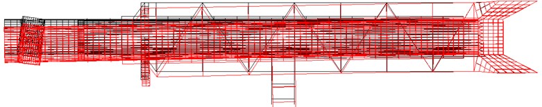
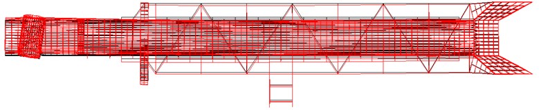
The aim was to reduce vibrations to an acceptable level and to increase the production capacity of the excavators, after some revitalization procedures. Expert analysis moved in two directions: the first – what is the impact of the excavator’s bucket wheel drive on increased vibrations of bucket wheel boom structure, and the second – what is the impact of buckets and cutting elements on increased boom vibrations. Fig. 1 shows the layout of the bucket wheel excavator ER1250.
In order to create the possibility for the excavator to provide the required capacity, it was necessary to increase the specific digging force of excavator i.e. to increase the installed power for the bucket wheel drive. By forecasted revitalization, installation of a new drive which will be increased from current 315 kW to 400 kW was planned. In addition, it was planned to introduce frequency regulation on the bucket wheel drive that will enable variable digging speed in the range from 50-120 % of the nominal speed.
The first step taken was the replacement of the bucket wheel drive. In other words numerical model of the bucket wheel boom was made first, then measured vibrations on the boom with the old drive, and then measured vibrations with the new drive. By the vibration measurements correctness of the structure and accuracy of the revitalization process by the replacement of the bucket wheel drive was proved. Vibrations are used as an excellent diagnostic tool that provide information for making the correct final stand point on further activities.
Many papers deal with vibration analysis of supporting steel structures for the bucket wheel excavators. In some papers [1-5] experimental results are listed and its interpretation is followed by the appropriate theoretical basis. There are a number of studies that present a numerical model based on finite elements method [4, 6-10]. However, numerical modelling often requires experimental verification, as it is mentioned in several papers [2, 4, 5, 11]. Vibrations and finite elements method are used to bring the correct stand point of bucket wheel excavator’s elements revitalization, which are based on the acceleration oscillation diagrams [12-17].
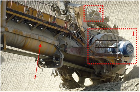
Fig. 1Operating body of the bucket wheel excavator ER1250; 1 – bucket wheel drive, 2 – bucket with cutting elements, 3 – tubular structure of the bucket wheel boom
2. Numerical model of the bucket wheel boom tubular structure
Due to the large number of vibration sources, isolation of own frequencies and the characteristic excitation frequencies is of the great importance to the elements, subassemblies and assemblies of any drive group on the bucket wheel excavator and especially for bucket wheel drive. The main form of oscillations make their own oscillation frequencies and its oscillation forms – main modes of oscillation. It should be especially noted, excitation and its own frequencies which are shown as an analytical calculation part of frequencies.
Large impact on the boom structure shape has bucket wheel disposition with drive aggregate. The shape of the boom is affected by the load, the required technology of excavation, the positioning of auxiliary structures, installations fitting, bucket wheel location, transfer points, conveyors and of course maintenance requirements. Bucket wheel boom belongs to the main supporting steel structure of the excavators. Boom is the most loaded and the most responsible part of the excavator structure. Large loads of the boom by dynamic and static forces, as well as by its own mechanisms and devices weight makes it extremely loaded structure with complex tension condition of high value. Boom represents approx. 10 % of the weight of the entire excavator.
The supporting boom structure should transfer all forces occurring in operation, transport and inactivity on the central excavator structure.
Type of the arranged boom structure depends primarily on the size of the excavator, and hence its boom. Following basic types of structures are applied:
– Boom structure with full walls,
– Boom structure in a grid shape, and
– Tubular boom structure.
The following impacts are main cause of fragile fracture in the supporting steel structure:
– The state of tension in the structural element,
– The speed of the load input to the structure, particularly in the form of impact loads,
– The built-in steel metallurgical properties, some of which may be an important phenomenon of carbon segregation in the cross-section, and the occurrence of non-metallic inclusions in the form of lunker,
– Temperature operating conditions, especially at low temperatures.
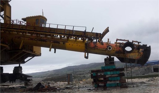
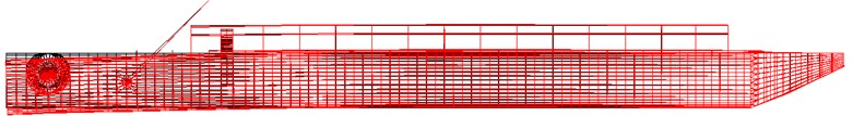
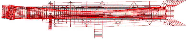
Structure strength diagnostics involves the analysis of the condition, behavior and structural deterioration as well as the assessment of the residual strength, operating life, mode of operation and revitalization extent. Analysis of the boom tubular structure means computer calculation using the finite elements method (FEM) and as mandatory, it requires experimental measurements. This allows determination of the actual structure behavior, a reliable forecast of its response in mining, obtaining choice and decision parameters, determination of reasons for bad or loosening behavior, assessment of exploitation lifetime and reliable operation lifetime. Fig. 2 provides the appearance of the bucket wheel ER1250 boom (dismantled elements of the drive and bucket wheel – with only a steel structure that is left).
Fig. 2BWE ER1250 bucket wheel boom with dismantled drive and bucket wheel
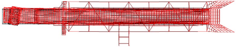
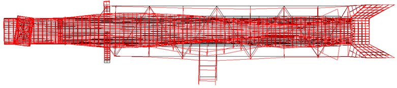
Model of tubular structure was made by using finite elements method. 5245 nodal points is defined in total, 703 linear finite elements and 5161 surface finite elements. Boom model is shown in Fig. 3.
Fig. 3Bucket wheel boom model
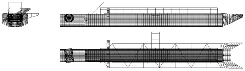
Fig. 4 provides a dynamic calculation of own frequencies and vibration (the first seven eigenshape).
Fig. 4The first seven eigenshape forms
a) The first eigenshape – 4,7 Hz (282 o/min)
b) The second eigenshape – 5 Hz (300 o/min)
c) The third eigenshape – 6,6 Hz (396 o/min)
d) The fourth eigenshape – 7,9 Hz (474 o/min)
e) The fifth eigenshape – 11 Hz (660 o/min)
f) The sixth eigenshape – 17 Hz (1020 o/min)
g) The seventh eigenshape – 22 Hz (1320 o/min)
Note that dominant frequencies of boom structure vibration are located at 5, 7, 8, 11, 17 and 22 Hz. Since excavator has the ability to perform digging with different speeds (introduced is frequency regulation) after revitalization, speeds that excess nominal (1000 min-1) and speeds at the level less than 70 % of the nominal speed (700 min-1) should be avoided. In other words, it means that digging process is in the range from 11 to 17 Hz, to avoid overlapping between the dominant structure frequencies and excitation frequencies (in this case from the bucket wheel drive).
3. Behavior of the bucket wheel boom tubular structures before replacement of the bucket wheel drive
Field vibration measurements were performed three times with old structure in March and June 2012 and after excavator’s revitalization, installation of new drive and bucket wheel in the March 2013. During the first measurements bucket wheel excavator has been operating in the regular block, and the material was with the increased resistance to digging.
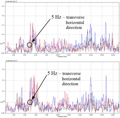
Measurements were carried out at the bucket wheel boom – the boom tube, i.e. on the 4 measuring points along the boom (Fig. 5). Fig. 6 shows the measuring results of the acceleration in the time and frequency domain on these measuring points. Applied color lines represent the following measuring directions: black line – transverse horizontal direction to the operating boom, red line – direction along the operating boom and a blue line – vertical direction.
Fig. 5Location of the acceleration measurement points on the boom
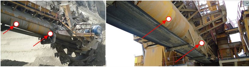
Fig. 6Typical vibration diagrams before revitalization
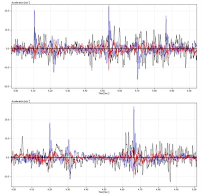
a) Time domain
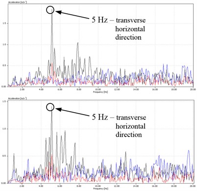
b) Frequency domain
Previous measurements on the bucket wheel boom points out to the unfavorable dynamic behavior, reflected in the following:
– it is registered extremely large acceleration values, ranging over 3G (Fig. 6 – time domain),
– dominant frequencies of the drive group and the boom are approx. 5, 6, and 8 Hz, that is 300, 360 and 480 min-1 (Fig. 6 – frequency domain);
– measured amplitudes (maximum values) for a frequency of 5 Hz were over 1,5 m/s2.
Such negative behavior comes mainly from suspension of the bucket wheel drive torque rod on the boom (in other words, from the drive itself), but also out from the cutting elements on buckets. Overlapping of the second, third and fourth form of the numerical model oscillation (5 Hz 300 min-1, 6.6 Hz 396 min-1, 7.9 Hz 474 min-1, Fig. 4), with the measured dominant drive group and boom frequencies should be specially emphasized (Fig. 6). The strong influence of excitation, both from the entry process and exit process of buckets from the digging process, and the elements of bucket wheel drive on diagrams in time domain (Fig. 6) is being noticed. For this type of vibration it can be said that it corresponds to excitation rotation frequencies of the bucket wheel gear elements.
Low frequencies are highly negatively related to the supporting steel structure, in this case tubular boom structure. Depending on the function of material fatigue, assessment was that at a certain time point it will come to failure, including the possible of structure breaking. This was one of the main reasons for the replacement of the old bucket wheel drive with new design and better suspension for the boom.
4. Behavior of the bucket wheel boom tubular structure after the bucket wheel drive replacement
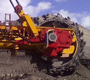
Revitalization of the excavator and replacement of the bucket wheel drive was done in the beginning of year 2013. New, modernized bucket wheel drive is shown in Fig. 7.
Fig. 7New drive of the bucket wheel excavator ER1250 operating body
Measurements after the performed revitalization were carried out during March 2013. Measurements were performed in the same points as during the measurements before revitalization of the drive group. During the measurement the same apparatus was used for the measurement. Fig. 8 shows acceleration results in the time and frequent domain after replacement.
Previous measurements on the bucket wheel boom indicates favorable dynamic behavior, which is reflected in the following:
– Lower but still high acceleration values in the range up to 1 G were recorded,
– Dominant frequencies of the drive group and boom are still about 5, 6 and 10 Hz (300, 360 and 600 min-1), but with a much lower amplitudes (maximum values were in the range up to about 0.1-0.15 m/s2);
– By the introduction of a new drive, a lot higher degree of the whole system rigidness was achieved (from the drive suspension for the boom, up to a new performance of the gearbox with smaller clearance and better finishing fabrication of gearbox interior elements);
– The value of measured amplitudes on the characteristic measuring points is for 10-15 times less than with the old performance of the bucket wheel drive (gearbox).
Measured accelerations confirmed the correctness of the bucket wheel drive replacement, i.e. measured vibrations provided numerical model confirmation, its validity and executed revitalization procedure. New drive group has raised the level of rigidness (especially in terms of reducing clearance and vibration damping), with better suspension of the bucket wheel boom structure, where it had a positive effect on the behavior of the boom supporting steel structure.
However, we still have a relatively poor behavior. This behavior further originates from the cutting elements of the buckets. It should be noted that digging conditions were much better during the measurement with the old structure and that another series of measurements should be made when excavator is in digging operation of the material with higher rigidness. In other words, it is necessary to reconstruct cutting elements, to measure vibrations, and after that to make a decision for the future operations of the excavator.
Fig. 8Typical vibration diagrams after revitalization (time and frequency domain)
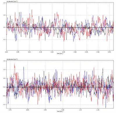
a) Time domain
b) Frequency domain
5. Conclusion
The supporting bucket wheel steel structure is the most responsible part on the bucket wheel excavator. It is actually a part of the bucket wheel excavator that defines its lifetime. Condition and behavior of the bucket wheel boom primarily depend on its geometry and its supports for a part of the structure with high levels of rigidness (higher weight in this case). The specificity of this structure is in its tubular form, which is unique case in the design of bucket wheel excavators in the world (mainly in question are lattice design and structure with full walls). This form should have a good condition and behavior under load, especially during twisting. However, due to possible material fatigue and weakening of the structure, especially at the local level, as well as an extremely hard material that is excavated, failure of structure may be expected. Expert analysis led to the conclusion that two courses of action can reduce the influence of load on the bucket wheel boom tubular structure. In both courses of action, measured vibrations are used up or could have been used as decisive parameters for making the correct attitude on the future operation. In addition, derived numerical model indicates issues of structural integrity of these types of bucket wheel excavators with possible failure locations of steel structure. Diagnosis of the condition and behavior by such complementary perception mode is gaining importance.
Therefore, one way was a revitalization procedure for the bucket wheel drive (gearbox) replacement. Vibration measuring before and after gearbox replacement, demonstrated the validity of the proceedings because the measured vibration with the new drive, up to 15 times less than with the old drive. Another way is defining new geometry of cutting elements (teeth) on the buckets of the bucket wheel (this way will be published in some other revitalization procedure). Thus, vibrations are used in a good way to define correctness of the revitalization proceedings by the replacement of the drive on the bucket wheel excavator ER1250, which is in operation on the opencast mine Gacko.
References
-
Pau A., Vestroni F. Modal analysis of a beam with radiation damping: numerical and experimental results. Journal of Vibration and Control, Vol. 13, Issue 8, 2007, p. 1109-1125.
-
Moon H. K., Lee M. C., Joun M. S. An approximate efficient finite element approach to simulating a rotary forming process and its application to a wheel-bearing assembly. Journal of Finite Elements in Analysis and Design, Vol. 44, 2007, p. 17-23.
-
Behzad M., Asayesh M. Numerical and experimental investigation of the vibration of rotors with loose discs. Proceedings of the Institution of Mechanical Engineers, Part C: Journal of Mechanical Engineering Science, Vol. 224, Issue 1, 2010, p. 85-94.
-
Maneski T., Jovančić P., Ignjatović D., Milošević-Mitić V., Maneski M. Condition and behaviour diagnostics of drive groups on belt conveyors. Journal of Engineering Failure Analysis, Vol. 22, 2012, p. 28-37.
-
Feng Z., LiangM. Complex signal analysis for wind turbine planetary gearbox fault diagnosis via iterative atomic decomposition thresholding. Journal of Sound and Vibration, Vol. 333, 2014, p. 5196-5211.
-
Jovančić P., Ignjatović D., Tanasijević M., Maneski T. Load-bearing steel structure diagnostics on bucket wheel excavator, for the purpose of failure prevention. Journal of Engineering Failure Analysis, Vol. 18, 2011, p. 1203-1211.
-
Arsić M., Bošnjak S., Zrnić N., Sedmak A., Gnjatović N. Bucket wheel failure caused by residual stresses in welded joints. Journal of Engineering Failure Analysis, Vol. 18, 2011, p. 700-712.
-
Druesne F., Boubaker M. B., Lardeur P. Fast methods based on modal stability procedure to evaluate natural frequency variability for industrial shell-type structures. Journal of Finite Elements in Analysis and Design, Vol. 89, 2014, p. 93-106.
-
Rahmatalla S., Hudson K., Liu Y., Eun H. C. Finite element modal analysis and vibration-waveforms in health inspection of old bridges. Journal of Finite Elements in Analysis and Design, Vol. 78, 2014, p. 40-46.
-
Qiao X., Zhu C. The active unbalanced vibration compensation of the flexible switched reluctance motorized spindle. Journal of Vibration and Control, Vol. 20, Issue 13, 2014, p. 1934-1945.
-
Rusinski E., Harnatkiewicz P., Kowalczyk M., Moczko P. Examination of the causes of a bucket wheel fracture in a bucket wheel excavator. Journal of Engineering Failure Analysis, Vol. 17, 2010, p. 1300-1312.
-
Brkić A. D., Maneski T., Ignjatović D., Jovančić P., Spasojević Brkić V. K. Diagnostics of bucket wheel excavator discharge boom dynamic performance and its reconstruction. Eksploatacja i Niezawodnosc – Journal of Maintenance and Reliability, Vol. 16, Issue 2, 2014, p 188-197.
-
Rusinski E., Czmochowski J., Iluk A., Kowalczyk M. An analysis of the causes of a BWE counterweight boom support fracture. Journal of Engineering Failure Analysis, Vol. 17, 2010, p. 179-191.
-
Bošnjak S., Pantelić M., Zrnić N., Gnjatović N., Đorđević M. Failure analysis and reconstruction design of the slewing platform mantle of the bucket wheel excavator O&K SchRs630. Journal of Engineering Failure Analysis, Vol. 18, 2011, p. 658-669.
-
Zuber N., Bajrić R., Šostakov R. Gearbox faults identification using vibration signal analysis and artificial intelligence methods. Eksploatacja i Niezawodnosc – Journal of Maintenance and Reliability, Vol. 16, Issue 1, 2014, p. 61-65.
-
Daničić D., Mitrović S., Ignjatović D., Kovačev S. Diagnostic approach to the revitalization of bucket wheel excavator. Conference Proceedings – Book 1, VII International Brown Coal Mining Congress “Role and Position of Brown Coal in the Global Power Industry of the 21st Century“, 2011, Bełchatów, Poland, p. 37-43.
-
Rusinski E., Moczko P., Pietrusiak D. Low frequency vibrations of the surface mining machines caused by operational loads and its impact on durability. Conference Proceedings, International Conference on Noise and Vibration Engineering ISMA, KU Leuven, Heverlee, Belgium, 2014, p. 683-694.
About this article

This article is a contribution to the Ministry of Science of Serbia funded projects TR035040 and TR033039.
