Abstract
A three-dimensional computational fluid dynamics (CFD) model of a labyrinth seal was established in order to investigate the influence mechanism of combined effects between bearings and labyrinth seals on the dynamic characteristics of the rotor-bearing-seal system. The dynamic coefficients of the labyrinth seal for various rotating speeds were calculated. Results show that the absolute values of cross-coupled coefficients increase with the increasing rotating speed, while the absolute values of direct coefficients decrease slightly. The positive preswirl at the inlet tends to intensify the increase of cross-coupled coefficients and the decrease of direct coefficients. The negative preswirl shows the opposite effect. A finite element model was further setup. Results show that the labyrinth seal has a large influence on the synchronous response of rotor in the resonant region due to its damping effect. For other speeds, it has a minor effect. The labyrinth seal may promote the instability of the rotor-bearing-seal system. The subsynchronous vibration increases significantly when the seal force is taken into account. The system stability can be generally enhanced by introducing the negative preswirl at the inlet. Results also show that the detrimental influence of the labyrinth seal can be compensated by using suitable bearings. A proper bearing configuration can be designed to reduce the risks of rotordynamic instabilities due to seals. An experimental test was finally performed, and it shows good agreements with the numerical simulation.
1. Introduction
Many instability faults of rotor, such as fluid-induced vibration, have been observed in turbomachineries in recent years. With the improvement of the working medium parameters in modern ultra-supercritical steam turbines, more and more unstable vibration problems were reported in HP/IP cylinders. These faults not only relate to the bearing but also the seal. The need exists to investigate the mutual combined effect between the bearing and seal on the synchronous and subsynchronous vibration.
Thomas and Alford [1, 2] first studied the rotor whirl instability mechanism. It was indicated that the major destabilizing force acting on turbomachinery stages is a cross-coupled force. Its magnitude is proportional to the radial deflection of the rotor and it acts in the direction orthogonal to the deflection. The cross-coupled force tends to promote the whirling motion of rotor and results in unstable vibration faults. Kim [3] studied the stability of a turbine rotor system with Alford forces. He integrated the structural model of a rotor system with the turbine flow model to examine effect of Alford forces on the structural stability of the rotor system. This force includes not only the unsteady aerodynamic blade or impeller forces, but also the forces induced by bearings and seals. To investigate the influence of dynamics of bearings and seals on the system stability, a lot of research has been carried out to evaluate the effect of bearings and seals on the rotor dynamics individually [4-9].
A HP/IP turbine system generally contains the rotor, bearing and seal. All these factors should be considered as a whole. However, such theoretical and experimental research based on the rotor-bearing-seal system has been rare. Hirano [10] evaluated the unstable vibration induced by the labyrinth seal of a large scales steam turbine. The stabilities of the steam turbines are confirmed to be in a stable region. Wang [11] studied the nonlinear dynamic behaviors of a rotor-bearing-seal system. Wang showed the destabilization influence of the leakage flow inside an interlocking seal on the system stability. Li [12] proposed a novel nonlinear model of a rotor-bearing-seal system based on the Hamilton principle and conducted numerical analysis. Ma [13] studied the nonlinear dynamic analysis of a rotor-bearing-seal system under two loading conditions at high speeds. It was found that the second loading condition (out-of-phase unbalances of two discs) and the nonlinear seal force can mainly restrain the first mode instability and have slight effects on the second mode instability. Yan [14] presented a transient CFD procedure to investigate the nonlinear dynamic performance of the rotor-seal system. The previous studies emphasized the nonlinear characteristics of the rotor-bearing-seal system. In addition, they mainly employed the Muszynska model based on a Jeffcot rotor system which made a lot of assumptions and neglected the gyroscopic effect of the rotor.
This paper further studied the influence mechanism of the combined effect between bearings and seals on the synchronous and subsynchronous vibration of the rotor-bearing-seal system. Finite difference method was used to obtain the stiffness and damping coefficients of bearings. Numerical studies using CFD techniques were presented to analyze the dynamic coefficients of the labyrinth seal. A finite element model of the rotor-bearing-seal system was further setup to analyze the rotor dynamics based on a test rig. Finally, an experimental measurement was carried out, and the combined effects between bearings and labyrinth seals were also observed from the experimental results in the test rig.
2. Test facility and apparatus
The experimental research was carried out on the fluid-induced vibration test rig. As show in Fig. 1, the test rotor is supported on two bearings lubricated by ISO VG32 turbine oil. The dimensions of the two bearings are shown in Table 1. The rotor is driven by a 15 kW variable-speed motor through a gearbox (4.5:1) via two rigid couplings. The maximal rotating speed and inlet pressure are 6000 rpm and 0.8 MPa respectively. Two balance disks are mounted at the two ends of the rotor to change the vibration. Total length and mass of the rotor are about 1.259 m and 70.92 kg respectively. The cylinder is supported by springs in the vertical, horizontal and axial directions. There are 6 sets of seals in the cylinder. High-pressure air enters the seal through four inlet holes in the center plane of the cylinder (3 sets of seals for each side). Fig. 2 shows the geometry and dimensions for one set of seals.
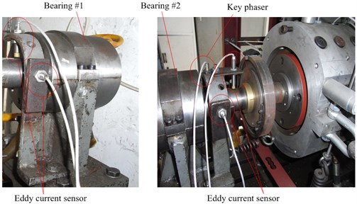
As shown in Fig. 3, four eddy current sensors are installed at the two ends of rotor to measure the rotor vibration in the vertical and horizontal direction. A key phase transducer is used to measure the rotating speed and phase. The test conditions are shown in Table 2.
Fig. 1Schematic diagram of the seal test rig
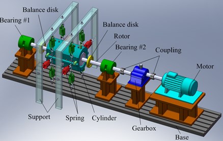
Fig. 2Dimensions of one set of the seal ring
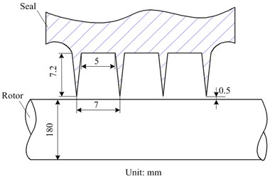
Table 1Bearing dimensions
Properties | Case 1 | Case 2 | Case 3 | Case 4 |
Diameter (mm) | 50 | 50 | 50 | 50 |
Width (mm) | 50 | 44 | 44 | 44 |
Radius clearance (mm) | 0.025 | 0.025 | 0.025 | 0.025 |
Pad angle (deg) | 130 | 150 | 150 | 150 |
Preload factor | 0 | 0 | 0.25 | 0.45 |
Table 2Operating conditions
Properties | Data |
Fluid | Compressed air |
Temperature (K) | 300 |
Inlet pressure (MPa) | 0.55 |
Outlet pressure (MPa) | 0.10 |
Fig. 3Displacement of sensors
3. Numerical model of the rotor-bearing-seal system
The main purpose by setting up the present model is to analyze the influence of the labyrinth seal on the system dynamics and the combined effect between the bearings and seals. The computation models in this section are built based on the test rig in order to ensure the reliability and validity of the numerical simulation.
3.1. General model for the bearing
The general formula for the film force in bearings can be defined by the following linearized force-displacement model:
where define the motion of the rotor relative to its stator, are the components of the reaction force acting on the rotor. and are the stiffness and damping coefficients, respectively.
For the bearing dynamics, much previous work has been done. This paper adopts the solution model based on Reynolds equation and perturbation method [15].
3.2. Solution model for the labyrinth seal
For small motion of the rotor about a centered position, a simpler model for the seal dynamics can be reduced from Eq. (1) as:
Previous studies [16-20] using CFD techniques show that the details of the flow field inside seals prove to be simulated close to the fact. In this paper, Reynolds-Averaged-Navier-Stokes (RANS) CFD analysis of the flow field inside the labyrinth seal is performed in ANSYS FLUENT. An advantage of using CFD is its capacity to analyze a large number of complex design configurations and parameters, and it makes no fundamental assumptions on geometry, shear stress at the wall, as well as internal flow structure. The equations can be written in Cartesian tensor form as:
where denotes a scalar such as velocity, pressure, energy, or species concentration ( 1, 2, 3).
ANSYS FLUENT is a finite-volume-based code, and it solves the equations for conservation of mass, momentum, and energy in terms of the dependent variables, velocity and pressure. Three-dimensional computational grid is generated using Gambit 2.2 software. A completed 360 degrees model with eccentric rotor is established to obtain the dynamic coefficients of the labyrinth seal. The eccentricity of the rotor is 0.05 mm, which equals 10 % of the tip clearance.
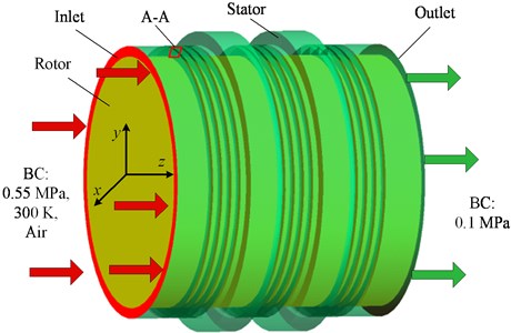
Fig. 4 shows the calculation model and boundary conditions defined for the labyrinth seal. The calculation assumes the fluid to be an ideal gas at constant temperature and the entire flow to be turbulent. The RNG - model and standard wall functions are used for the calculation. The momentum equations, the continuity equation, and the turbulence model equations are solved using the SIMPLE pressure-velocity coupling algorithm. Second-order upwind discretization is employed for the continuity, momentum and energy equations, and the pressure is discretized with standard scheme. Pressure is specified at the inlet and outlet boundary. In addition, the inlet boundary is set with zero preswirl, positive (+30 deg) preswirl and negative (–30 deg) preswirl individually. A no slip and an adiabatic boundary condition are imposed for the stator wall and rotor surface.
Since the dynamic coefficients of the labyrinth seal are of interest in present study, the rotating frame of reference is adopted for the calculation at a specific rotating speed [16, 17]. In the rotating frame of reference, the fluid rotates at the same speed with the rotor around the eccentric axis. A solution is obtained at multiple whirl frequency ratio values. After solutions with various whirl speeds are obtained, the seal force of each case is calculated by integrating the pressure on the rotor surface as follows:
where is the rotor radius; is the flow passage length in the axial direction; is the uneven pressure acting on the rotor surface.
Fig. 4Calculation model and boundary conditions
Assuming the effect of inertia is negligible, the dynamic coefficients can be derived from the following equations:
where , are direct and cross-coupled stiffness coefficients, , are direct and cross-coupled damping coefficients, , are seal forces in radial and tangential directions, is whirling speed, and is eccentricity.
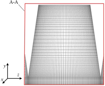
The mesh density study is firstly performed to investigate the effect of mesh density and to know how fine of a mesh is required to capture the important flow physics. The grid elements are clustered along the walls in order to capture the details of the boundary layers. The ratio is set to 1.05. This process includes incremental adjustments to grid size. As a result of this analysis, the total number of nodes for the current calculation model is about 5.5 million. The final mesh in the meridional plane (A-A Section in Fig. 4) is shown in Fig. 5. Near wall values are also checked to ensure that the mesh is appropriate for application of the wall functions. Values of the dimensionless wall distance (+) lie between 37 and 243, which is acceptable for the wall functions in the model.
Fig. 5Schematic diagram of computation grid
3.3. Finite element model of rotor-bearing-seal system
A finite element analysis model using ANSYS was built for the rotor-bearing-seal system. The gyroscopic effect of rotor was taken into account in the model. The labyrinth seal locates between the bearing #1 and #2, and its influence is considered by an equivalent of the dynamic coefficients obtained from the above computation model.
The dynamic equation of the rotor-bearing-seal system with external excitation can be written in the following form:
where , and are structural mass matrix, damping matrix, and stiffness matrix of the rotor-bearing-seal system; and are damping and stiffness matrix of the bearings; and are damping and stiffness matrix of the labyrinth seal; , and are nodal acceleration, velocity vector, and displacement vector; is external excitation force vector.
QR Damped Method was applied to obtain the unbalance response. The eigenvalues are given by:
where is the th complex eigenvalue, , and are the real and imaginary part of the th eigenvalue, respectively.
The logarithmic decrement is presented in order to analyze the stability of the rotor-bearing system. The logarithmic decrement represents the logarithm of the ratio of two consecutive peaks in the dynamic response. It can be expressed as:
where is the logarithmic decrement of the th eigenvalue, and are the real and imaginary part of the th eigenvalue, respectively.
4. Numerical results and analysis
4.1. Dynamic coefficients of the labyrinth seal
Fig. 6 shows the dynamic coefficients of the labyrinth seal under different patterns of preswirl vs. rotating speed. It can be seen that the absolute values of cross-coupled terms increase with the increasing rotating speed, while the absolute values of direct coefficients decrease slightly. The positive preswirl at the inlet tends to intensify the increase of cross-coupled coefficients and decrease of direct coefficients. The negative preswirl shows the opposite effect.
Fig. 6Dynamic coefficients of the labyrinth seal vs. rotating speed
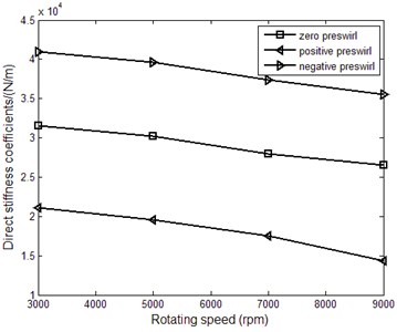
a) Direct stiffness coefficients
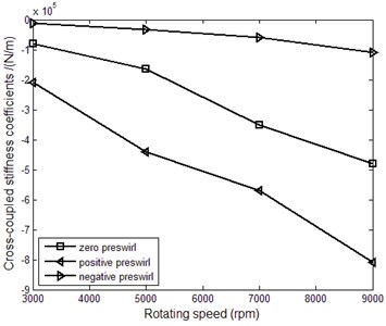
b) Cross-coupled stiffness coefficients
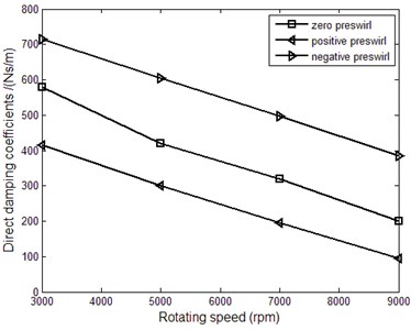
c) Direct damping coefficients
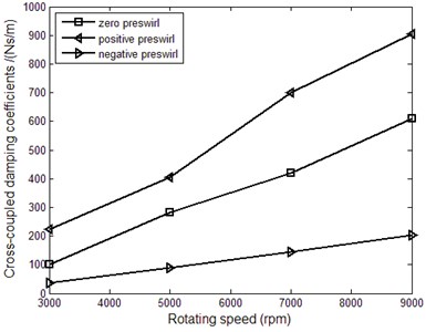
d) Cross-coupled damping coefficients
4.2. Influence of labyrinth seal on the synchronous response of rotor
Fig. 7(a) shows the influence of seal force on the unbalance response of rotor under the case of zero preswirl. The first order critical speed is almost 2700 rpm. It can be seen that the labyrinth seal weakens the unbalance response of rotor significantly in the resonant region, as shown in the region between the two dotted lines in Fig. 7(a). While it shows little influence on the unbalance response for other speeds. This is mainly because the damping effect of the labyrinth seal plays a leading role in the resonant region, as shown in Fig. 7(b). For other speeds, the stiffness coefficients of the labyrinth seals are minor comparing with that of the bearings.
4.3. Influence of labyrinth seal on the stability of rotor-bearing-seal system
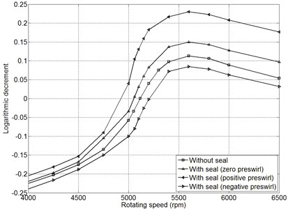
The system stability is evaluated by the logarithmic decrement, and the system will be unstable as soon as the logarithmic decrement is greater than zero. Fig. 8 shows the changing logarithmic decrements of the rotor-bearing-seal system under different rotating speeds. It can be seen that the destabilization speed is about 5116 rpm when the system is under operation without seal. While the destabilization speeds under the action of the seal force with zero preswirl, positive preswirl, and negative preswirl become approximately 5053, 4940, 5200 rpm, respectively. The labyrinth seal may promote the occurrence of instability, and it can also delay the appearance of the destabilization speed due to different patterns of preswirl. The system stability can be generally enhanced by introducing the negative preswirl at the inlet. This agrees with the results by Rajakumar [5]. Results also shows that the influence of the labyrinth seal on the system stability becomes more and more remarkable with the increasing rotating speed.
Fig. 7Synchronous response of rotor
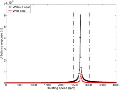
a) Unbalance response vs. rotating speed
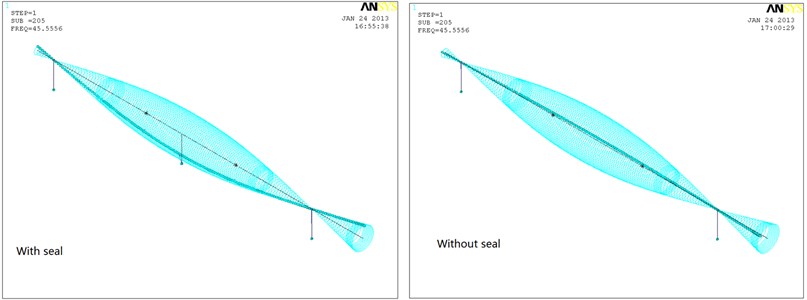
b) The whirling orbits for the first order critical speed
Fig. 8Logarithmic decrements corresponding to the first mode of rotor under different rotating speeds
4.4. Influence of bearing performance on the stability of rotor-bearing-seal system
Four kinds of journal bearings are selected to study the influence of bearing performance on the system stability. The preload factor, bearing width and pad angle are different for the four cases. Table 1 gives the detailed dimensions of each bearing.
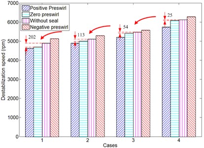
Fig. 9 shows the bar diagram of destabilization speeds for different cases of bearings. The destabilization speed without seals increases gradually from Case 1 to Case 4. When the labyrinth seal is taken into account, the biggest drop (202 rpm) of the destabilization speed can be observed for Case 1. Its influence becomes minimal for Case 4. This is mainly because of different patterns of bearings for the four cases. From Table 1, the bearing stability for Case 1 is the worst due to its small preload factor and specific pressure, and the bearing for Case 4 with the largest preload factor performs best. It can be seen that the bearing performance plays a critical role in the stability of the rotor-bearing-seal system. The detrimental influence of the labyrinth seal can be compensated by using suitable bearings.
Fig. 9Destabilization speed for different cases of bearings
5. Test results and discussion
5.1. Influence of labyrinth seal on rotor synchronous vibration during running up process
Fig. 10 shows the Bode diagram for the bearings #1. The critical speeds are about 2400 rpm and 3300 rpm in the horizontal and vertical direction respectively. This difference is mainly due to the differences of pedestal dynamics between the horizontal and vertical directions in the test rig. Noticed that there is a small peak corresponding to 3400 rpm in the horizontal direction, and there is also a small peak corresponding to 2600 rpm in the vertical direction. This can be explained that there is a strong coupling effect between the two directions. The influence of the seal force on the rotor vibration can be mainly seen in the region nearby the critical speed, as shown in the region between the two dotted lines in Fig. 10. The amplitude of rotor vibration in the zone decreases significantly when the seal force is added. The damping effect of the labyrinth seal plays a dominant role in the resonant region. These results agree with the above numerical simulation well.
5.2. Influence of labyrinth seal on the destabilization speed of rotor-bearing-seal system
Fig. 11 shows the waterfall plots corresponding to the bearing #2. The synchronous frequency (1X) is the main component of the rotor vibration before 5000 rpm. The subsynchronous frequency (1/2X) appears when the rotating speed approaches 5000 rpm. The vibration corresponding to this frequency becomes more and more serious with the increasing rotating speed. When the compressed air is introduced, the rotating speed becomes about 4800 rpm. There is a 200 rpm change of the onset speed corresponding to the subsynchronous frequency (1/2). Notice that the subsynchronous vibration for 5100 rpm increases from 30 um to 60 um approximately when the seal force is taken into account. The seal force tends to promote the system instability.
Fig. 10Rotor vibration changes vs. rotating speed
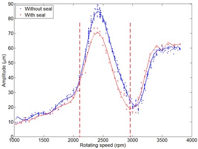
a) In horizontal direction
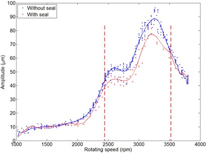
b) In vertical direction
Fig. 11Waterfall plots for bearing #2
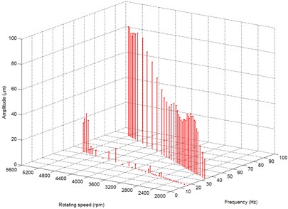
a) In horizontal direction without seal
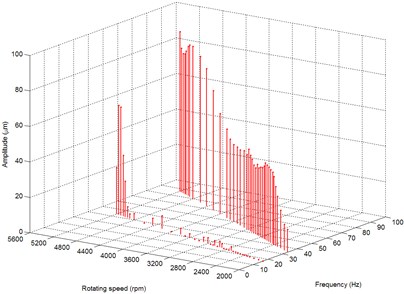
b) In horizontal direction with seal
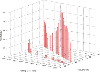
c) In vertical direction without seal
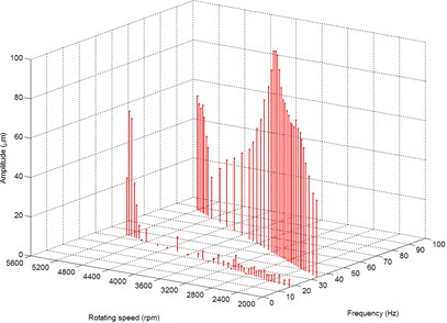
d) In vertical direction with seal
6. Conclusions
This paper analyzes the influence mechanism of combined effects between bearings and seals on the rotor-bearing-seal system dynamics through numerical simulation and experimental research. Results show that the labyrinth seal has a large influence on the synchronous response of rotor in the resonant region due to its damping effect. For other speeds, it has a minor effect. The labyrinth seal may promote the instability of rotor-bearing-seal system. The subsynchronous vibration increases significantly when the seal force is taken into account. The system stability can be generally enhanced by introducing the negative preswirl at the inlet.
Results also show that the bearing performance plays a critical role in the stability of the rotor-bearing-seal system. The detrimental influence of the labyrinth seal can be compensated by using suitable bearings. The unstable vibration faults always can be observed in HP/IP cylinders. A proper bearing configuration can be designed to reduce the risks of rotordynamic instabilities due to seals.
References
-
Thomas H. J. Unstable natural vibration of turbine rotors induced by the clearance flow in glands and blading. Bull. de I’AIM, Vol. 71, Issues 11-12, 1958, p. 1039-1063.
-
Alford J. S. Protecting turbomachinery from self-excited rotor whirl. Journal of Engineering for Power, Vol. 87, 1965, p. 333.
-
Kim H. S., Cho M., Song S. J. Stability analysis of a turbine rotor system with Alford forces. Journal of Sound and Vibration, Vol. 258, Issue 4, 2002, p. 777-790.
-
Muszynska A. Stability of whirl and whip in rotor/bearing systems. Journal of Sound and Vibration, Vol. 127, Issue 1, 1988, p. 49-64.
-
Rajakumar C., Sisto F. Experimental investigations of rotor whirl excitation forces induced by labyrinth seal flow. Journal of Vibration and Acoustics, Vol. 112, Issue 4, 1990, p. 515-522.
-
Yucel U. Effects of Labyrinth Seals on the Stability of Rotors. Lehigh University, Bethlehem, PA, USA, 2000.
-
Qin P. Dynamic analysis of hydrodynamic bearing-rotor system based on neural network. International Journal of Engineering Science, Vol. 43, Issue 5, 2005, p. 520-531.
-
Akhmetkhanov R., Banakh L., Nikiforov A. Flow-coupled vibrations of rotor and seal. Journal of Vibration and Control, Vol. 11, Issue 7, 2005, p. 887-901.
-
Hua J. Numerical analysis of nonlinear rotor-seal system. Journal of Sound and Vibration, Vol. 283, Issue 3, 2005, p. 525-542.
-
Hirano T. Evaluation of rotordynamic stability of a steam turbine due to labyrinth seal force. Challenges of Power Engineering and Environment, Proceedings of the International Conference on Power Engineering, 2007, p. 361-367.
-
Wang W. Z. Nonlinear analysis of orbital motion of a rotor subject to leakage air flow through an interlocking seal. Journal of Fluids and Structures, Vol. 25, Issue 5, 2009, p. 751-765.
-
Li W. A novel nonlinear model of rotor/bearing/seal system and numerical analysis. Mechanism and Machine Theory, Vol. 46, 2011, p. 618-631.
-
Wang H., Li H., Niu H., et al. Nonlinear dynamic analysis of a rotor-bearing-seal system under two loading conditions. Journal of Sound and Vibration, Vol. 332, 2013, p. 6128-6154.
-
Yan X., He K., Li J., et al. Numerical techniques for computing nonlinear dynamic characteristic of rotor-seal system. Journal of Mechanical Science and Technology, Vol. 28, Issue 5, 2014, p. 1727-1740.
-
Jang G., Lee S. Determination of the dynamic coefficients of the coupled journal and thrust bearings by the perturbation method. Tribology Letters, Vol. 22, Issue 3, 2006, p. 239-246.
-
Hirano T., Guo Z., Kirk R. G. Application of computational fluid dynamics analysis for rotating machinery – Part 2: labyrinth seal analysis. Journal of Engineering for Gas Turbines and Power, Vol. 127, Issue 4, 2005, p. 820-826.
-
Moore J. J., Ransom D. L., Viana F. Rotordynamic force prediction of centrifugal compressor impellers using computational fluid dynamics. Journal of Engineering for Gas Turbines and Power, Vol. 133, Issue 4, 2011, p. 042504-10.
-
Yan X., Li J., Feng Z. Investigations on the rotordynamic characteristics of a hole-pattern seal using transient CFD and periodic circular orbit model. Journal of Vibration and Acoustics, Vol. 133, Issue 4, 2011, p. 041007-9.
-
Nielsen K. K., Jonck K., Underbakke H. Hole-pattern and honeycomb seal rotordynamic forces: validation of CFD-based prediction techniques. Journal of Engineering for Gas Turbines and Power, Vol. 134, Issue 12, 2012, p. 122505-10.
-
Li J., Li Z., Feng Z. Investigations on the rotordynamic coefficients of pocket damper seals using the multifrequency, one-dimensional, whirling orbit model and RANS solutions. Journal of Engineering for Gas Turbines and Power, Vol. 134, Issue 10, 2012, p. 102510-11.
About this article

Financial supports from National Natural Science Foundation of China (Nos. 11402148, 51275088, 51176129, 51276116) were sincerely acknowledged.
