Abstract
Neural networks-based intelligent identification of structural damage mostly accentuates the capability of neural networks to recognize damage patterns but somewhat makes relatively less noticeable to the effect of structural dynamics in delivering an efficient damage identification scheme as well as damage features. At present, modal frequencies are often selected as inputs to neural networks for predicting location and/or severity of damage; however, this practice lacks solid support by structural dynamics. For that reason, this study investigates the use of structural dynamics-guided neural networks for damage identification. Structural dynamic analysis indicates that there are explicit relations between damage location and the ratio of changes of modal frequencies (RCMFs), and between damage severity and the change in modal frequencies (CMFs), before and after damage. These relations lay the foundation for creating a hierarchical neural-networks scheme to identify damage: using the RCMFs as inputs and damage location as the output to frame neural networks for locating damage; using the CMFs as inputs and damage severity as the output to establish neural networks for quantifying damage. This scheme features the guidance of structural dynamics on choosing damage indices and establishing a neural networks structure. The proposed scheme is numerically verified by identifying the location and severity of cracks in beams, with emphasis on noise robustness, and it is further experimentally validated using a set of steel beams with a through-width transverse crack, showing high accuracy and reliability in damage location and quantification.
1. Introduction
Neural networks-based intelligent identification of structural damage has received considerable attention in civil, aerospace and mechanical engineering communities [1, 2], primarily because of the remarkable capabilities of neural networks to learn from training as well as to imitate the way humans manage and process information. With the use of trained neural networks, structural damage states may be assessed and predicted, even without a priori information about the physical or numerical model of the structure [3].
Representative studies of neural networks-based intelligent diagnosis of structural damage are briefly described here. Chang et al. [4] proposed a damage detection method based on structural parameter identification using an iterative neural networks technique. The effectiveness of that method was corroborated by numerical and experimental cases of damage identification in clamped-clamped beams. Sung et al. [5] predicted impact damage in a 330 mm×330 mm×3 mm graphite/epoxy laminate by exploiting a neural-networks paradigm, with the prediction error of less than 5 mm. Xu et al. [6] used adaptive multilayer perceptron (MLP) networks to correctly identify cracks in anisotropic laminated plates [C0/G+45/G-45]. Zang and Imregun [7] used principal component analysis (PCA)-condensed frequency responses functions (FRFs) as inputs to neural networks for damage detection. The results showed accurately detected damage in a railway wheel. Ni et al. [8] constructed neural networks for hierarchical identification of the location and extent of damage in steel frames from measured modal properties. The neural networks effectively identified the damage location(s) in multi-damage cases. Zubaydi et al. [9] devised neural networks for identifying damage in the side shells of a ship structure, demonstrating the capability of the neural networks to judge the occurrence of damage. Sahin and Shenoi [10] utilized a combination of changes in modal frequencies and curvature mode shapes as inputs to neural networks to locate and quantify damage in beam-like structures. The algorithm was experimentally validated using cantilever beams with a slot. Yam et al. [11] exploited combined neural networks and wavelet transforms to detect crack damage in polyvinyl chloride sandwich plates and verified the capability of the method to locate and quantify damage. Reddy and Ganguli [12] used radial-basis-function neural networks (RBNNs) fed with rotation frequencies to assess damage in a soft in-plane hingeless helicopter rotor blade. Their results showed that the approach identified damage accurately. Kao and Hung [13] devised a method for identifying damage via free vibration responses generated by approximating neural networks, with the feasibility of the method verified by numerical and experimental cases. Xu et al. [14] developed a novel neural networks-based strategy for directly identifying stiffness and damping coefficients from structural time-domain dynamic responses. The accuracy of the strategy was demonstrated using numerical cases of 5-storey frames.
Fang et al. [15] devised an algorithm of using neural networks with a tunable steepest descent algorithm for damage detection. Their results showed that the neural networks detected damage in a cantilevered beam with great accuracy. Lee et al. [16] utilized mode shape differences as inputs to neural networks to detect damage. The experimental results demonstrated that the method effectively distinguished damage in bridges under traffic loadings. Yeung and Smith [17] employed neural networks for damage pattern recognition with dynamic response spectra as damage features to detect damage in a suspension bridge. A reliable damage identification rate of about 70 % was achieved even with a moderate amount of noise added to the dynamic response signals. Ni et al. [18] identified seismic damage in a scale model of a 38-storey building using PCA-condensed FRFs and neural networks, and reported the merits of the PCA in improving accuracy of identification. Bakhary et al. [19] created statistical neural networks to assess structural condition by taking into account the effect of uncertainties, with the reliability of the method experimentally validated. Lee and Kim [20] extracted a signal anomaly index from structural dynamic responses as input to neural networks for damage detection. The capacity of the index to characterize damage was demonstrated by experimental and numerical cases of a damaged model bridge. Rajakarunakaran et al. [21] devised neural networks for fault detection in a centrifugal pumping system and reported accurate detection of various faults in the system. Mehrjoo et al. [22] estimated the damage intensity of joints in truss bridge structures using back-propagation-based neural networks, with the damage intensity quantified with great accuracy. Park et al. [23] proposed an approach for detecting damage using two neural networks with acceleration responses and modal quantities as damage features, respectively. The capability of the approach was experimentally validated on beams.
Elshafey et al. [24] developed a neural-networks technique for identifying damage in an offshore structure using its free decay response and random excitations, with the effectiveness of the technique addressed. Luo et al. [25] proposed a combination of a fiber Bragg grating array and neural networks to detect damage in a plate. The capability of the method was experimentally validated. Jiang et al. [26] employed a combination of probabilistic neural networks and a data-fusion system to detect both single and multiple damage in a 7-storey steel frame. Their numerical results showed that the method accurately identified damage with strong robustness against noise. Saeed et al. [27] used multiple neural networks with modal frequencies and FRFs as inputs to estimate the size and location of cracks in curvilinear beams, and reported the superiority of multiple neural networks over single neural networks in crack characterization. Shu et al. [28] developed a scheme of using the statistical properties of structural dynamic responses as inputs to neural networks for damage detection. The performance of the scheme was clarified by numerical simulations of a one-span simply supported beam railway bridge with damage. Bal and Buyle-Bodin applied neural networks to predict dimensional changes of concrete structures due to drying shrinkage [29] and creep drying [30], with the evolution of drying shrinkage accurately predicted. Aydin and Kisi [31] utilized MLP and RBNNs to detect damage in Timoshenko beams. Their results showed that the optimal RBNNs model performed better than the optimal MLP in predicting the damage.
Most existing neural networks-based intelligent methods for identifying structural damage broadly exhibit a common characteristic: they highlight the capability of neural networks to recognize damage patterns but somewhat make relatively less noticeable to the function of structural dynamics in efficiently delivering damage features and an associated scheme of damage identification. In existing methods, damage features are generally determined in line with the premise that damage-induced changes in the physical properties, i.e., stiffness, mass, and/or damping, will in turn alter the dynamic characteristics of the structures, i.e., resonant frequencies, modal damping, and mode shapes. Unfortunately, this premise only gives the overall theoretical background of damage identification, but misses the explicit explication and clear indication of delivering effective damage features, resulting in some arbitrariness in selecting damage features. For instance, modal frequency is generally used as input to neural networks for predicting location and/or severity of damage [1, 4, 10]. Nevertheless, this practice lacks sufficient support by structural dynamics. Considering that the selection of highly sensitive features plays a crucial role in accurate identification of damage, acceptance of erroneous damage features necessarily impairs the performance of neural networks in recognizing damage patterns.
To address this limitation, this study focuses on developing structural dynamics-guided neural networks for structural damage identification, with emphasis on the guidance of structural dynamics to deliver damage features and frame the structure of neural networks. With this method, a structural dynamics-guided hierarchical neural-networks scheme is established, and its capability to progressively locate and quantify damage is numerically verified and experimentally validated using beams with through-width transverse cracks.
2. Fundamentals
2.1. Calibration of numerical model
An adequately sized data set that includes the information that can characterize the problem domain being explored is the basic requirement for neural networks to infer the underlying rule or mechanism of the problem domain. For damage detection, the data set refers to a damage sample spectrum that comprises numerous damage samples, sufficient to reflect the damage domain of interest. Construction of the damage sample spectrum poses a great challenge for physical model testing, requiring huge cost in material resources and manpower. In this situation, it is anticipated that a numerical model of the structure under inspection can be used to serve as an alternative to the physical model to generate a damage sample spectrum. Nevertheless, the creation of an effective numerical model involves the generic uncertainty of structural parameters, entailing calibration of the numerical model. One simple interpretation of calibration is the adjustment of one or several structural parameters associated with a numerical model until the model agreement is maximized with respect to a set of testing data. The calibration of a numerical model is commonly implemented by an optimization approach, in which calibration is cast as an cost function-minimizing process, with the cost function addressing the difference between measured and simulated data. The cost function is directly or indirectly related to the structural parameters.
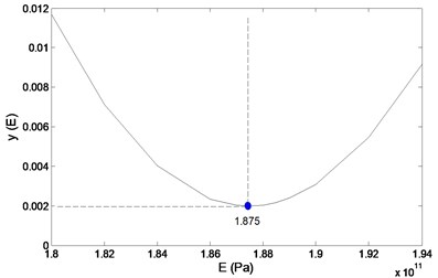
In this investigation, the elasticity modulus, , is selected as the calibration variable due to its stronger uncertainty and greater sensitivity to structural dynamic properties than other material parameters. With this calibration variable, the cost function for calibration of a numerical model is created by minimizing the sum of squared relative changes of pairs of simulated and measured modal frequencies:
where and denote the th numerically simulated and tested modal frequencies, respectively; is the number of modal frequencies used for model calibration.
By way of illustration, the process of minimizing for the optimal elasticity modulus, , of a numerical model for a cantilever steel beam is presented in Fig. 1, in which is determined by the minimum of : 1.875×10³ GPa. The calibrated numerical model can mathematically serve as a “prototype” of the actual structure being diagnosed, to yield a damage sample spectrum.
Fig. 1Illustration of calibrating a numerical model by adjusting E
2.2. Dynamics-guided damage features
Modal frequencies usually serve as damage features to characterize damage location, damage severity, or simultaneous location and severity of damage [1, 4, 10]. This practice is based on the basic premise that damage can change structural modal parameters, typically modal frequencies [10]. Nevertheless, this premise is formulated from an empirical rather than analytical point of view, lacking sophistication in portraying damage. In what follows, structural dynamic analysis is used to determine the influence of damage location or damage severity on modal characteristics so as to yield more reasonable and effective damage features.
The characteristic equations for free vibration of a structure in its pristine and damaged states can be written as [32], respectively:
where and are the global stiffness matrix, mass matrix, modal frequency, and normalized mode shape of the intact structure, respectively; and are the damage-induced changes in the stiffness matrix, mass matrix, modal frequency, and mode shape, respectively.
It is acknowledged that any damage, e.g., a crack, commonly changes the stiffness but not the mass of a structure. With this premise, the first order modal perturbation equation for the stiffness change , neglecting higher order terms of , can be expressed as [32]:
Pre-multiplying by for Eq. (4) and neglecting higher order terms of , gives:
Eq. (5) implies that change of modal frequency, , is essentially related to change of structural stiffness, .
Decomposition of the global stiffness matrix and mode shape into individual member stiffness matrices and mode shapes leads to:
Substitution of Eq. (6) into Eq. (5) yields:
From Eq. (7), an arbitrary damage member has:
The change in the stiffness matrix can be expressed as:
where is the fractional change in element of the member stiffness matrix, is a matrix related to damage location.
Substitution of Eq. (9) into Eq. (8) yields:
For two vibration modes and , the ratio of frequency changes is formed by:
Eq. (12) implies that the ratio of changes of modal frequencies (RCMFs) before and after damage is a sole variable function of [32], indicating the location of damage. Similarly, Eq. (5) suggests that the change in modal frequencies (CMFs) before and after damage is a dedicated index to characterize the severity of the damage. Therefore, RCMFs and CMFs are structural dynamics-guided damage features for locating and quantifying damage, respectively.
3. Hierarchical neural-networks scheme
Most neural networks-based methods of damage identification emphasize the capability of neural networks for intelligent recognition of damage patterns but somewhat neglect damage features in portraying damage [3-10], resulting in some arbitrariness in the choice of damage features. For example, a generic mode of using neural networks to identify damage adopts modal frequencies as inputs and location and severity of damage as outputs. Unfortunately, the underlying rule between modal frequencies and compound location and severity of damage is so complex that it creates a challenge for neural networks to recognize damage patterns. This consequence then entails the creation of structural dynamics-guided neural networks scheme for damage identification.
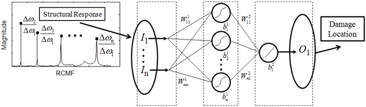
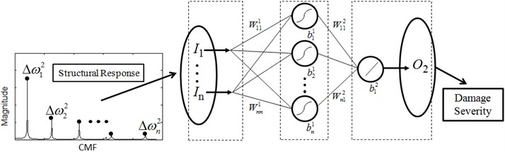
The observations from structural dynamic analysis in Section 2.2 [32] lay the foundation for selecting damage features, and further for constructing a hierarchical neural-networks scheme for damage detection. The explicit relation between RCMFs and damage location defined by Eq. (12) suggests that particular neural networks with RCMFs as inputs and damage location as output is suited to damage location, termed neural networks for damage location (NNDL); the distinct relation between CMFs and damage severity described in Eq. (5) implies that particular neural networks with modal frequency as inputs and damage severity as output is suited to damage quantification, termed neural networks for damage quantification (NNDQ). The joint NNDL and NNDQ constitute a hierarchical neural-networks scheme for damage identification. Under the guidance of structural dynamic theory, the hierarchical neural-networks scheme features uncoupling intractable damage identification into separate tractable subtasks of damage location and damage quantification. The schematic of the hierarchical scheme is illustrated in Fig. 2, where the frequency response functions are used to generate RCMFs and CMFs, i.e., the inputs for NNDL and NNDQ, respectively.
Fig. 2Hierarchical neural-networks scheme. I, W, b and O denoted input, weight, bias and output of a neural network, respectively
In damage identification applications, NNDL and NNDQ individually adopt sigmoid active functions in the hidden layer and linear active functions in the output layer, forming a multilayer feedforward neural network. Both NNDL and NNDQ are trained by the Levenberg-Marquardt algorithm due to its prominent advantages over existing algorithms.
4. Numerical proof of concept
The proof of concept of the hierarchical neural-networks scheme is performed by finite element (FE) simulation, with the intention of demonstrating the feasibility and potential of the scheme. With the hierarchical scheme, damage locating damage by NNDL and quantifying damage by NNDQ are successively implemented on a FE model of a cantilever steel beam of which the prototype is described in the experiment section.
4.1. Numerical model of cracked beam
The geometric and material parameters of the numerically simulated cantilever steel beam are tabulated in Table 1. The FE model of the beam is built with 8-node 3D solid elements using the commercial software ABAQUS. This FE model is used as a base from which to build the damage sample spectrum. A crack, specified by the relative location ratio (RLR) from the fixed end, , and the relative depth ratio (RDR), , is introduced into the FE model to create the damage case. The crack is modeled using a null-thickness interface on which the coincident nodes in adjacent but separate structural elements are distributed [33], as shown in Fig. 3. The influence of the crack on the first six modal vibrations is illustrated by a damage case specified with 17 % and 30 % (Fig. 4). Variations of and can evoke various damage samples, and those samples adequate to characterize the damage domain constitute the damage sample spectrum. For damage identification using NNDL and NNDQ, the damage sample spectrum comprises 160 damage scenarios, identified by a crack located at 2, 3.2, 6, 11, 17, 26, 32, 38, 42, 46, 50, 58, 66, 74, 86, 93 %, respectively, with ranging from 5 % to 50 % in steps of 5 % at each location of damage.
Fig. 3FE model of cantilever beam with zoomed-in crack
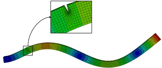
Fig. 4First six-order modal vibrations of cantilever beam with a crack of α= 17 % and β= 30 %
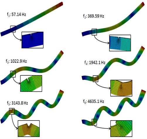
Table 1Geometry and material parameters of numerical beam
Geometry | Material | ||||
Length (mm) | Width (mm) | Height (mm) | Young’s modulus (GPa) | Poisson’s ratio | Mass density (kg/m3) |
500 | 12 | 19 | 1.875 | 0.3 | 7750 |
4.2. Damage identification
Identification of damage is performed by successive manipulations: first locating damage by NNDL with RCMFs as inputs, and then quantifying damage by NNDQ with CMFs as inputs. The damage sample spectrum (160 damage samples) is divided into two sets: a training set of 136 damage samples (85 % per cent of the spectrum), a test set of 24 damage samples (15 % per cent of the spectrum). The performances of NNDL or NNDQ initialized with random values are evaluated by mean-squared errors between the genuine and the predicted parameters of damage.
4.2.1. Damage location
The well-trained NNDL is fed with RCMFs obtained from the test set of damage samples, yielding predictions of damage locations. Comparison of the predictions with the actual damage locations (Fig. 5) shows that 56.52 %, 73.91 %, and 91.30 % of the predictions have relative errors lower than 5 %, 10 %, and 25 %, respectively, indicating the good capacity of the NNDL to locate damage.
Fig. 5Comparison between predicted and actual locations of damage
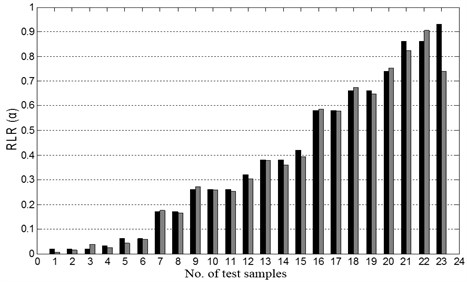
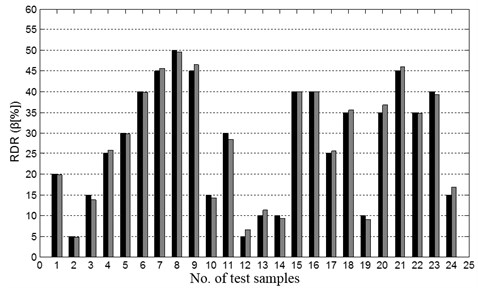
Fig. 6Comparison between predicted and actual severity of damage
4.2.2. Damage quantification
Fed with the CMFs from the test set of damage samples, the well-trained NNDQ outputs the estimates of damage severity. Comparisons of the estimates and actual damage locations (Fig. 6) show that 70.83 %, 87.50 %, and 95.83 % of the predictions have relative errors lower than 5 %, 10 %, and 15 %, respectively, demonstrating the strong capacity of the NNDQ to quantify damage.
4.2.3. Accuracy assessment
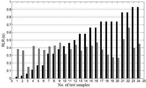
The general mode of neural networks, using modal frequencies as inputs and damage location as output, is also used to conduct damage identification. The prediction results of damage locations are shown Fig. 7. None of the estimates of damage location have relative errors lower than 10 %, and only 4.17 % of the estimates have relative errors lower than 15 %. Comparison of the NNDL with the general mode of neural networks-based damage location demonstrates that NNDL has superior capability in locating damage. Similar observations can be found for NNDQ in damage quantification. These results show that structural dynamics lays the foundation for creating an effective neural networks model for structural damage identification.
Fig. 7Estimated damage location by general mode of neural networks
4.3. Robustness against noise
The robustness against noise of the hierarchical neural-networks scheme is investigated by adding white Gaussian noise to clear modal frequencies to yield noisy modal frequencies, from which noisy CMFs and RCMFs can be derived. The white Gaussian noise is added by the Matlab function , where and denote clear and noisy data, respectively, and is the parameter of the signal-to-noise ratio (SNR). Noisy RCMFs are used as alternatives to the clear RCMFs for damage location, and noisy CMFs are used as alternatives to the clear CMFs for damage quantification. Noise robustness is investigated for noise levels ranging from SNR = 90 dB to 30 dB in steps of 10 dB.
4.3.1. Damage location
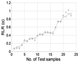
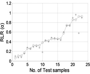
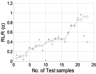
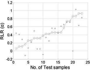
The well-trained NNDL is fed with the noisy RCMFs from the test damage samples for prediction of damage locations. Fig. 8 shows the test results with SNR = 90, 70, 50, and 40 dB, respectively. These figures indicate that measurement noise inconsequentially affect the accuracy of the hierarchical neural-networks program in identifying damage location when the SNR > 50 dB. The proposed hierarchical neural-networks program is able to identify the location reasonably well even under noisy conditions.
4.3.2. Damage quantification
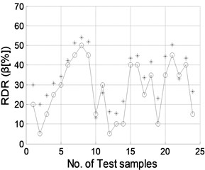
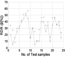
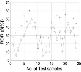
The well trained NNDQ is fed with the CMFs from the test set of damage samples, yielding predicted severity of damage, as shown in Fig. 9. Gaussian white noise with SNRs of 90, 70, 50, and 40 dB is individually added to the CMFs as inputs of the hierarchical neural-networks. Similar phenomena are found to those for damage location, in that damage severity can be predicted well when the SNR is no less than 70 dB.
Fig. 8Damage location predicted by NNDL using noisy RCMFs with SNRs of a) 90 dB, b) 70 dB, c) 50 dB, and d) 40 dB, respectively. (“o”: real damage location; “*”: predicted damage location)
a)
b)
c)
d)
Fig. 9Damage severity predicted by NNDQ using noisy CMFs with SNRs of a) 90 dB, b) 70 dB, c) 50 dB, and d) 40 dB, respectively. (“o”: real damage severity; “*”: predicted damage severity)
a)
b)

c)
d)
5. Experimental validation
5.1. Experimental set-up
The proposed scheme is experimentally validated using six steel beams each with a transverse through-width crack created by a wire-cutting machine (Fig. 10). The crack is described by the parameters of RLR and RDR, as shown in Table 2 for all the test samples. The geometric and material properties of each beam can be approximately described by the FE model’s parameters in Table 1, since the FE model is calibrated using the test sample, as described in Section 2.1. Dynamic testing is performed on each beam with a fixed-free boundary condition.
Table 2Crack dimensions for test samples
Beam no. | 1 | 2 | 3 | 4 | 5 | 6 |
RLR (%) | 26.66 | 26.66 | 26.66 | 26.66 | 46.66 | 66.66 |
RDR (%) | 10 | 20 | 30 | 40 | 40 | 40 |
To excite the beam, an impulse load imposed by a hammer with a force transducer is applied at a point near the free end. While the beam is vibrating, an accelerometer, located 410 mm distant from the fixed end, is utilized to measure the transverse acceleration response of the beam. The responses of force and acceleration are individually registered for a total of 65,536 sampling points with the sampling frequency 12.8 kHz. The acquired responses of force and acceleration can produce frequency response functions, from which RCMFs and CMFs can be derived for damage identification. The dynamic testing set-up together with the data acquisition system (uTeKL) are shown in Fig. 11.
Fig. 10Transverse crack fabricated by wire-cutting machine

Fig. 11a) Dynamic testing set-up and b) data acquisition system
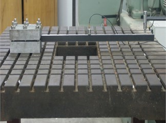
a)
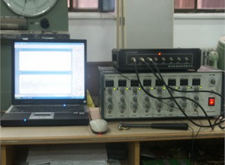
b)
5.2. Hierarchical damage identification
When neural networks are used to recognize damage patterns, an accurate numerical model of test specimens is needed to produce sufficient training samples. A crucial factor for creating an accurate numerical model is the technique of numerical model calibration. The process of searching optimal is shown in Fig. 1, with the resulting optimal being 1.875 GPa, identical to that given in Table 1.
The training of the hierarchical neural networks was illustrated in Section 3. The well-trained NNDL and NNDQ are used for locating and quantifying damage, respectively. The prediction results are tabulated in Table 3, in which the prediction errors for damage location and damage severity are also presented. From Table 3, several observations can be obtained: (1) the NNDL is competent to locate damage with the maximum error of less than 8 %; (2) the NNDQ is capable of quantifying damage with the maximum error of less than 9 %; (3) the error magnitude of damage location is not correlated with the distance between the damage and the clamped end of the beam; (4) the error is more significant with increase of the distance between the damage and the clamped end of the beam.
Table 3Results yielded by NNDL and NNDQ
Damage cases | Damage description | Predicted result | Prediction errors | |||
RLR (%) | RDR (%) | RLR (%) | RDR (%) | RLR (%) | RDR (%) | |
1 | 26.66 | 10 | 32.55 | 10.1485 | 5.89 | 0.1485 |
2 | 26.66 | 20 | 29.62 | 17.6914 | 2.96 | –2.3086 |
3 | 26.66 | 30 | 28.71 | 28.2683 | 2.05 | –1.7317 |
4 | 26.66 | 40 | 34.42 | 38.1811 | 7.76 | –1.8189 |
5 | 46.66 | 40 | 4647 | 35.9772 | –0.19 | –4.0228 |
6 | 66.66 | 40 | 67.04 | 31.3006 | 0.38 | 8.6994 |
6. Conclusions
A hierarchical neural networks scheme for identifying damage in beams is developed based on structural dynamic analysis. The explicit relations revealed by structural dynamic analysis between damage location or damage severity and the derivative of modal frequencies lay the foundation for selecting damage features and further creating a hierarchical neural-networks scheme comprising joint NNDL and NNDQ: NNDL locates damage using RCMFs prior and posterior to damage as inputs and damage location as the output to train neural networks; NNDQ quantifies damage relying on the use of CMFs before and after damage as inputs and damage severity as the output to characterize the damage domain. The proposed scheme is numerically verified and experimentally validated by identifying the location and severity of cracks in cantilever steel beams, with great accuracy, strong reliability, and superiority over existing methods.
References
-
Wu X., Ghaboussi J., Garret Jr. J. H. Use of neural networks in detection of structural damage. Computers and Structures, Vol. 42, Issue 4, 1992, p. 649-659.
-
Cao M. S., Qiao P. Z. Neural network committee-based sensitivity analysis strategy for geotechnical engineering problems. Neural Computing and Applications, Vol. 17, 2000, p. 509-519.
-
Sun Z., Chang C. C. Structural damage assessment based on wavelet packet transform. Journal of Structural Engineering, Vol. 128, Issue 10, 2002, p. 1354-1361.
-
Chang C. C., Chang T. Y. P., Xu Y. G., Wang M. L. Structural damage detection using an iterative neural network. Journal of Intelligent Material Systems and Structures, Vol. 11, Issue 1, 2000, p. 32-42.
-
Sung D. U., Oh J. H., Kim C. G., Hong C. S. Impact monitoring of smart composite laminates using neural network and wavelet analysis. Journal of Intelligent Material Systems and Structures, Vol. 11, Issue 3, 2000, p. 180-190.
-
Xu Y. G., Liu G. R., Wu Z. P., Huang X. M. Adaptive multilayer perceptron networks for detection of cracks in anisotropic laminated plates. International Journal of Solids and Structures, Vol. 38, Issue 32, 2001, p. 5625-5645.
-
Zang C., Imregun M. Structural damage detection using artificial neural networks and measured FRF data reduced via principal component projection. Journal of Sound and Vibration, Vol. 242, Issue 5, 2001, p. 813-827.
-
Ni Y. Q., Wang B. S., Ko J. M. Constructing input vectors to neural networks for structural damage identification. Smart Materials and Structures, Vol. 11, 2002, p. 825-833.
-
Zubaydi A., Haddara M. R., Swamidas A. S. J. Damage identification in a ship’s structure using neural networks. Ocean Engineering, Vol. 29, Issue 10, 2002, p. 1187-1200.
-
Sahin M., Shenoi R. A. Quantification and localisation of damage in beam-like structures by using artificial neural networks with experimental validation. Engineering Structures, Vol. 25, Issue 14, 2003, p. 1785-1802.
-
Yam L. H., Yan Y. J., Jiang J. S. Vibration-based damage detection for composite structures using wavelet transform and neural network identification. Composite Structures, Vol. 60, Issue 4, 2003, p. 403-412.
-
Reddy R. R. K., Ganguli R. Structural damage detection in a helicopter rotor blade using radial basis function neural networks. Smart Materials and Structures, Vol. 12, Issue 2, 2003, p. 232-241.
-
Kao C. Y., Hung S. L. Detection of structural damage via free vibration responses generated by approximating artificial neural networks. Computers and Structures, Vol. 81, Issue 28-29, 2003, p. 2631-2644.
-
Xu B., Wu Z., Chen G., Yokoyama K. Direct identification of structural parameters from dynamic responses with neural networks. Engineering Applications of Artificial Intelligence, Vol. 17, Issue 8, 2004, p. 931-943.
-
Fang X., Luo H., Tang J. Structural damage detection using neural network with learning rate improvement. Computers and Structures, Vol. 83, Issues 25-26, 2005, p. 2150-2161.
-
Lee J. J., Lee J. W., Yi J. H., Yun C. B., Jung H. Y. Neural networks-based damage detection for bridges considering errors in baseline finite element models. Journal of Sound and Vibration, Vol. 280, Issues 3-5, 2005, p. 555-578.
-
Yeung W. T., Smith J. W. Damage detection in bridges using neural networks for pattern recognition of vibration signatures. Engineering Structures, Vol. 27, Issue 5, 2005, p. 685-698.
-
Ni Y. Q., Zhou X. T., Ko J. M. Experimental investigation of seismic damage identification using PCA-compressed frequency response functions and neural networks. Journal of Sound and Vibration, Vol. 290, Issues 1-2, 2006, p. 242-263.
-
Bakhary N., Hao H., Deeks A. J. Damage detection using artificial neural network with consideration of uncertainties. Engineering Structures, Vol. 29, Issue 11, 2007, p. 2806-2815.
-
Lee J., Kim S. Structural damage detection in the frequency domain using neural networks. Journal of Intelligent Material Systems and Structures, Vol. 18, Issue 8, 2007, p. 785-792.
-
Rajakarunakaran S., Venkumar P., Devaraj D., Rao K. S. P. Artificial neural network approach for fault detection in rotary system. Applied Soft Computing, Vol. 8, Issue 1, 2008, p. 740-748.
-
Mehrjooa M., Khajia N., Moharramia H., Bahreininejadb A. Damage detection of truss bridge joints using artificial neural networks. Expert Systems with Applications, Vol. 35, Issue 3, 2008, p. 1122-1131.
-
Park J.-H., Kim J.-T., Hong D.-S., Ho D.-D., Yi J.-H. Sequential damage detection approaches for beams using time-modal features and artificial neural networks. Journal of Sound and Vibration, Vol. 323, Issues 1-2, 2009, p. 451-474.
-
Elshafey A. A., Haddara M. R., Marzouk H. Damage detection in offshore structures using neural networks. Marine Structures, Vol. 23, Issue 1, 2010, p. 131-145.
-
Luo P., Zhang D., WangL., Jiang D. Structural damage detection based on a fiber Bragg grating sensing array and a back propagation neural network: an experimental study. Structural Health Monitoring, Vol. 9, Issue 1, 2010, p. 5-11.
-
Jiang S. F., Fu C., Zhang C. M. A hybrid data-fusion system using modal data and probabilistic neural network for damage detection. Advances in Engineering Software, Vol. 42, Issue 6, 2011, p. 368-374.
-
Saeed R. A., Galybin A. N., Popov V. Crack identification in curvilinear beams by using ANN and ANFIS based on natural frequencies and frequency response functions. Neural Computing and Applications, Vol. 21, Issue 7, 2011, p. 1629-1645.
-
Shu J., Zhang Z., Gonzalez I., Karoumi R. The application of a damage detection method using Artificial Neural Network and train-induced vibrations on a simplified railway bridge model. Engineering Structures, Vol. 52, 2013, p. 408-421.
-
Bal L., Buyle-Bodin F. Artificial neural network for predicting drying shrinkage of concrete. Construction and Building Materials, Vol. 38, 2013, p. 248-254.
-
Bal L., Buyle-Bodin F. Artificial neural network for predicting creep of concrete. Neural Computing and Applications, Vol. 25, Issue 6, 2014, p. 1359-1367.
-
Aydin K., Kisi O. Damage detection in Timoshenko beam structures by multilayer perceptron and radial basis function networks. Neural Computing and Applications, Vol. 24, Issues 3-4, 2014, p. 583-597.
-
Hwarn G., Testa R. B. Modal analysis for damage detection in structures. Journal of Structural Engineering, Vol. 117, Issue 10, 1991, p. 3042-3063.
-
Cao M. S., Qiao P. Z. Integrated wavelet transform and its application to vibration mode shapes for the damage detection of beam-type structures. Smart Materials and Structures, Vol. 17, Issue 5, 2008, p. 55014.
About this article

The authors gratefully acknowledge the financial support provided by the Natural Science Foundations of China (Grant No. 11172091), Qing Lan Project and the Fundamental Research Funds for the Central Universities (Grant Nos. 2014B03914 and 2012B05814), and the Youth Science Foundations of Nanjing Hydraulic Research Institute (Grant No. Y413004).
