Abstract
The complex impulse environment of the artillery firing process brings very tough vibration attenuation requirement of the artillery-mounted equipment. The experiment is designed to decrease an artillery mounted instrument container’s vibration. However, after being equipped with a certain rubber shock absorber, the vibration of this instrument container wasn’t being controlled. Thus, based on the theoretical analysis and dynamic simulation, we summarized that this phenomenon was caused by the rigid collision between two parts of the rubber shock absorber while reaching elastic limit. The result provides the necessary theory of choosing the appropriate artillery shock absorber. By using the Genetic Algorithm optimization design method, we found the best independent variable .
1. Introduction
The artillery firing process is accompanied with high temperature, high speed, high pressure and complex strong impact. These factors make the artillery different from the other mechanical system. Here are the problems that the artillery mounted instrument should face during the firing process: when the connector without additional tightening measures fall from the slot, it may cause other components’ damage; resonance occurs when the natural frequency and excitation frequency is the same [1]; mechanical deformation of the structure of the device and brittle fracture; screw connection loosen or even fall off and hit other parts. Therefore, it is very important to eliminate the vibration of the artillery carrier equipment.
Besides eliminating vibration, vibration absorption, damping, dynamic design, the most widely used measurement is vibration isolation technology [2]. With the excellent characters of noise reduction performance and low cost, the rubber shock absorber are widely used in various mechanic structure. The rubber shock absorber’s properties are mainly reflected by the response of mechanic structure under dynamic loads. The loads of artillery firing is highly transient, and non-cyclical, therefore the response under the transient complex dynamic loads of the artillery firing is very important [3-6].
2. Experiment of rubber shock absorber
The object of this experiment, instrument container, can directly influent the working situation of the artillery as one of the artillery carrier equipment [7]. Since it can suffer massive instantaneous shock impact loads when the artillery is firing, some reasonable shock absorptions are very necessary to ensure that the instrument container can work safely.
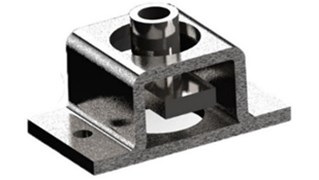
A certain rubber shock absorber was chosen for this experiment and illustrated as Fig. 1. This shock absorber is combined of three parts, mounting base, rubber filler and mounting bracket. The mounting base and mounting bracket are made of cast iron. The inner situation is shown as Fig. 2. Instead of rigid connection, rubber materials with the rigidity and damping are filled between the mounting base and bracket [8, 9].
Fig. 1Rubber shock absorber
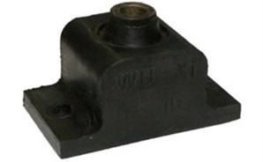
Fig. 2Inner situation of absorber
According to the mechanic handbook, the rigidity of this kind of rubber shock absorber is 500 N/mm, and the damping ratio is 0.1 while the maximum static deformation is 1 mm. By considering the size and structure of this equipment, these four rubber shock absorbers were installed in the four bottom corners of the instrument container. What’s more, eight M6 threaded fasteners were used to fix this system.
The accelerator sensors were stuck on the instrument container by the adhesives, approaching the 4 corners with large stiffness. The comparison experiments were conducted by the variables-control method. The independent reproducible of the experiments were secured by the control of system input. Physical comparison signals were the vibration signals before and after of shock damping. The acceleration acquisition system was consisted of the acceleration transducer, the charge amplifier and the data collector.
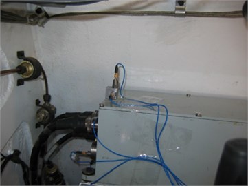
The field experiment system is illustrated as Fig. 3.
Fig. 3Field experiment system
According to the actual order of magnitude of test signal, the range of MSI-BR-CH-50 charge amplifier can be obtained as ±10000 pC. In order to make sure that the data was synchronous, this three acceleration channels were triggered by the same negative edge voltage which was set as 5 V. The acquisition time was set between –1000 ms to 1000 ms so as to obtain the data in the whole vibration process. According to the signal frequency spectrum and the sampling theorem, the sample frequency of each channel was set as 10 kHz.
The obtained acceleration signals needed to be transformed by making use of the unification principle. The irregular pulse acceleration signal should be equalized to half-sine waveform and evaluated by the tolerance half-sine waveform evaluation.
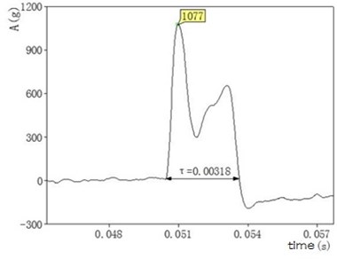
Now we transformed an accelerating signal detected in an impulse experiment. By using Fast Fourier Transform and choosing a good cutoff frequency to filter, the data images are shown as Figs. 4-5.
Semi-sinusoidal equivalent processing was standard half-sine whose impulse amplitude was and pulse duration was . After the integration process, we obtained its velocity as following:
Fig. 4Data image before waveform filtering
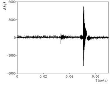
Fig. 5Data image after waveform filtering
With the above filtering and half-sine equivalent treatment, we preceded four groups of experimental data. The results are shown in Table 1.
Table 1Four groups of experimental data
Test number | Before the shock | After the shock | ||
Acceleration peak (g) | Pulse width (ms) | Acceleration peak (g) | Pulse width (ms) | |
1 | 4 | 10 | 51 | 3.5 |
2 | 12 | 3 | 25 | 20 |
3 | 8 | 4.5 | 60 | 2.5 |
4 | 10 | 3.5 | 71 | 2.5 |
3. Analysis of vibration system
Based on the experimental phenomena of shock reduce system’s impact peak acceleration increasing, this section explains it according to the system dynamic and collision. First of all, since the rubber shock absorber’s mass was much smaller than the instrument container, the shock absorber model could be simplified as the combination of a spring unit with 2000 N/mm and damping unit with 0.8 N⋅s/mm. Furthermore, the whole system could be simplified as a single degree of freedom damped mass-spring system after introduced the instrument container, which had a certain mass. According to the theory of mechanical vibrations, after the semi-sinusoidal equivalent excitation on the rubber shock absorber mounting bracket, the mass unit response of single degree of freedom damped mass-spring system was [10]:
where is the instrument container’s mass, is the damp of rubber shock absorber, was the natural frequency of the single degree of freedom mass-spring system, and were the initial displacement and initial velocity of the vibration system.
was the response of the single degree of freedom damped mass-spring system based on the initial conditions.
was the response of the single degree of freedom damped mass-spring system based on the equivalent incentives.
Since the initial state of the experimental system under gravity was static equilibrium, the response caused by the initial conditions is zero. The response of the mass of single degree of freedom damped quality spring system can be simplified as:
Based on previous vibration theory, MATLAB is used to calculate the system response by using the convolution and differential operation. The speed and acceleration of instrument container was shown as Figs. 6-7.
Fig. 6Speed of instrument container
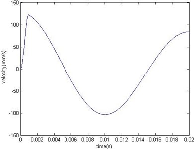
Fig. 7Acceleration of instrument container
By installing the shock absorber, the peak acceleration of this dynamic model was about 20 g which is less than the one without shock absorber. Single degree of freedom damped mass-spring system did not appear to increase the acceleration phenomenon. Therefore the damped spring-mass system may reach the elastic limit of the spring and in a non-compressed state which caused the instantaneous collision. It would lead to a sharp increase in instantaneous acceleration and affect the safe operation of the instrument container and life.
In multi-body dynamics software Adams, the system dynamics model was built up as show in Fig. 8.
The kinetic model was composed of four parts, which were damper base, shock absorber bracket, instrument container and a spring damper unit. First, the direction of gravity and the gravity value of the whole system were set. Then the constraint relationship of each part was set up, damper base was fixed on the ground, instrument container was fixed on the shock absorber bracket, spring shock absorber damping element acting between the bracket and the damper base was set between the two sliding pair member, which limiting the direction of movement. Finally, semi-sinusoidal excitation was applied on the shock absorber bracket equivalent. Defined the contact parameters damper between the base and the shock absorber bracket based on the collision function contact algorithm.
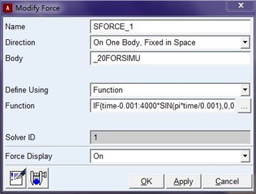
Semi-sinusoidal equivalent excitation was set as IF ( 0.001:4000∙(0.001), 0, 0), which means it was the 4000 N peak value half-sine during the 0 and 0.001 s and none incentives after 0.001 s. The direction status was on one body and fixed in space. ADAMS modify window is shown as Fig. 9.
Fig. 8System dynamics model
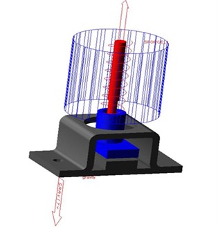
Fig. 9The window of modifying the force
Spring damper unit parameter was set as the stiffness coefficient 2000 N/mm, the damp coefficient 0.8 N⋅s/mm. And the preload of this spring was zero as well as the length derived from design position. ADAMS modify window is expressed as Fig. 10.
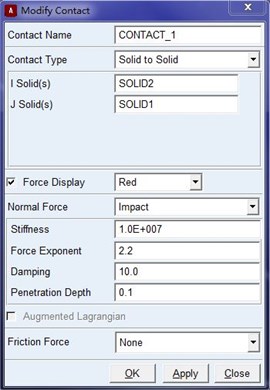
The contact between the instrument container and the shock absorber bracket was set as the style solid to solid. And the stiffness between the instrument container and the shock absorber bracket was 107 N/mm. Instantaneous normal force in the material stiffness contribution index was 2.2, while the damping was 10 N⋅s/mm. Full damping penetration depth was 0.1 mm. The actual ADAMS modify window are shown as Fig. 11.
Fig. 10The window of modifying the spring
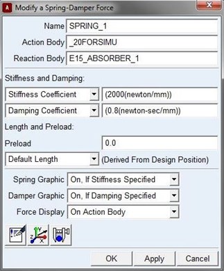
Fig. 11The window of modifying the contact
Before dynamics simulation, the static equilibrium system was reached to restore the true initial state, which allowed the springs in pre-compressed state under the control of instrument container. Setting simulation time 0.02 s, computed nodes 2000 and finally running the simulation calculation.
The numerical calculation theory of ADAMS is Fourier integral response under arbitrary excitation. The displacement function can be expressed in equation:
where, is complex frequency response function, and:
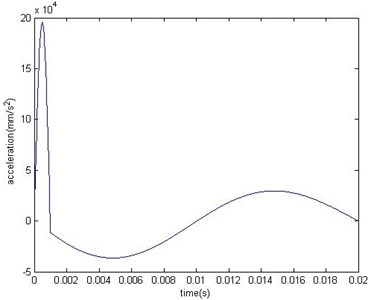
Simulation speed and acceleration of instrument container were shown as Figs. 12, 13.
Fig. 12Speed of instrument container
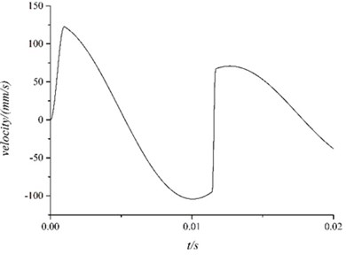
Fig. 13Acceleration of instrument container
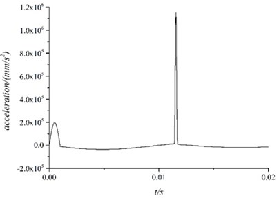
The conclusion can be reached according to the pictures:
From 0 to 0.001 s, the instrument container’s velocity increased to 125 mm/s and produced acceleration whose peak was about 20 g.
After 0.001 s, the outer stimulation disappeared and the instrument container moved under the spring damping unit with a certain amount of compression. The vibration of the entire system could be described as the free oscillation damping with the initial state.
About 0.0115 s, the velocity of the instrument container changed rapidly. From the view of model, it could be described as follow. After lost the outer stimulation , the instrument container moved under the effect of spring damper unit. When it came to the reverse maximum speed, the spring means reaches its maximum compression 0.1 mm, which caused the fierce collision and caused measured acceleration surge.
4. Genetic algorithm optimization design
In the early 1970s, Prof. Holland and his students proposed and founded a new kind of optimization algorithm named genetic algorithm in University of Michigan. This algorithm based on Darwin’s natural evolution and genetic mechanism which was firstly applied to simulate survival of the fittest was brought into the mechanical engineering field finally. And this algorithm was developed rapidly into a kind of optimization algorithm named adaptive heuristic probabilistic global search method. Since 1980s, genetic algorithm has been applied in many areas, such as automatic control, robotics and engineering design [11].
In genetic algorithm, the task of the genetic operation is exerting a certain operation about the groups of individuals according to their fitness to the environment, so as to realize the evolutionary process of evolution. From the view of optimization search, genetic operation can optimize the solution one after another generation and approximate optimal solution finally.
Genetic operation include the following three basic operators: selection, crossover and mutation. The three genetic operators has the following features. For individual genetic operators of all operations are carried out under the condition of random disturbance, as a result, the rule of approximating the optimal solution of the migration is random. But, this kind of randomization operations is different from the traditional random search method for genetic operations with direction is more effective. The effect of the genetic operation is relative to operation probability, encoding methods, group size, initial population and fitness function.
Selection describe the process of choosing the superior individuals and eliminating the inferior individuals. Sometimes we call the selection operator as the reproduction operator. The purpose of selection is inheriting the optimization individuals directly or the new individuals by matching cross produce to the future generations. Select operation is established on the basis of evaluating the fitness of individuals in the group including the fitness proportion method, the random traversal sampling method, the local law choice and so on. The roulette wheel selection method is the simplest and most commonly used selection method. In this method, the selection probability of each individual is proportional to its fitness value.
The genetic recombination plays the core role in the process of biological evolution. So, the core role of genetic algorithm is the crossover operator of genetic operations. Crossover refers to replacing the two parent individuals to generating the structure reorganization individuals. Through this kind of crossover, the searching ability of genetic algorithm increases a lot. Crossover operator can produce a new gene combination by crossing two individuals randomly from the population rate of exchange of certain genes expecting the combining of the beneficial genes. According to the coding method, crossover method can be classified into the following algorithm: discrete recombination, intermediate recombination, linear recombination, extended linear recombination, single-point crossover, multiple-point crossover, uniform crossover, shuffle crossover and crossover with reduced surrogate. The most common crossover operator is single-point crossover.
The basic content of mutation operator is changing a certain genes value of the individuals. According to the individual coding representation method, mutation operator can be classified into the following algorithm: the real value mutation and the binary mutation.
The purpose of binging in the mutation includes two parts. One is making the genetic algorithm have local random search capabilities. When the answer is close to the optimal solution neighborhood, using the mutation operator of the local random search ability can accelerate convergence to the optimal solution. Obviously, such a case the mutation probability should take lesser value, or the optimal solution due to the variation of building block will take damage. Another is maintaining the population diversity to prevent premature convergence phenomenon. At this time, the convergence probability should take larger value.
In genetic algorithm, the crossover operator is the main operator for its global search ability, and the mutation operator is the auxiliary operator for its local search ability. Through the cooperation and competition with each other, crossover and mutation balances both global and local search ability.
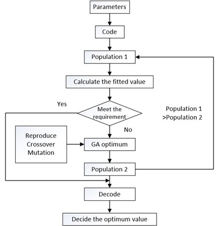
When the fitness of the best individual reaching the threshold, or the fitness of the best individual stopping rising, or the number of iterations reaching algebra, the algorithm will be terminated. Default algebraic average generation is set from 100 to 500. The whole optimization design process can be described as show in Fig. 14.
Based on hertz contact theory, the calculation of contact force model was set as the impact function provided by the nonlinear equivalent spring damper. According to impact function calculating the contact force between the two components, the contact force is composed of two parts. One is due to the interaction between the two components are cut and the elastic force, while the other one is generated by the relative velocity damping force.
Its general form can be represented as below:
where, refers Hertz contact stiffness, units of N/mm. In general, larger stiffness value caused more difficult to integral, but if the stiffness value is too small, will not be able to simulate the real contact between two components. refers the normal penetration of the contact point, the unit is mm. refers the damping coefficient.
Fig. 14The optimization design process
When it comes to this rubber shock absorber contact optimization design problem. The objective function was illustrated in equation:
where, the response of the mass of single degree of freedom damped quality spring system was . means the velocity of the instrument container at the time 0.02 s. means the stiffness of the spring while refers hertz contact stiffness between the absorber and the instrument container. means the displacement of the instrument container at the time 0.02 s. By taking two derivative, we got the acceleration of this system. The objective function was obtained by integrating the acceleration from 0 s to 0.02 s. And refers the maximum static deformation as the variable. The constraint condition is shown as Eq. (11):
MATLAB is a business mathematical software produced by the American MathWorks company. It could be applied in algorithm development, data visualization, data analysis and numerical calculation of senior technical computing language and interactive environment, mainly consisting of MATLAB and Simulink.
MATLAB is the combination of two words matrix and laboratory, meaning a matrix laboratory, published by the American MathWorks company mainly face of scientific calculation, visualization and interactive program design of the high-tech computing environment. It assembles the numerical analysis, matrix calculation, scientific data visualization and nonlinear dynamic system of modeling and simulation, and many other strong function integration in a convenient windows environment. MATLAB provides a comprehensive solution for scientific research, engineering design and must be effective numerical calculation many fields of science.
Then, the genetic algorithm optimization design can be written in MATLAB language. The selection, crossover and mutation procedure code is shown in Figs. 15-17.
Fig. 15Genetic algorithm selection code
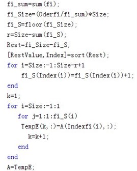
Fig. 16Genetic algorithm crossover code
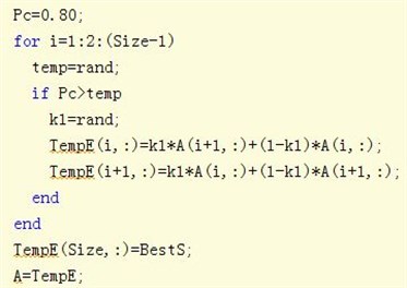
Fig. 17Genetic algorithm mutation code
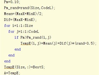
Fig. 18Absorber command file
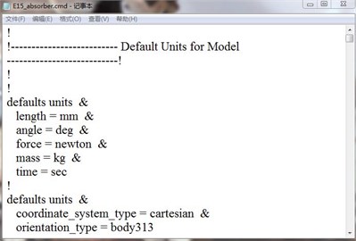
The parameters in the objective function was obtained in ADAMS View Postprocess, and the independent variable, maximum static deformation of the absorber was changed by writing the ADAMS command file in the program Wordpad which is shown as Fig. 18.
Finally, we found the minimum of the objective function at the 5.869688 mm.
5. Conclusions
In order to reduce the effect of the complex impulse environment during artillery firing, an experiment is designed to control the artillery mounted instrument container’s vibration, by choosing one rubber shock absorber. The experiment’s result shows that this project is useless and brings about more uncertain vibration. Using collision theory and dynamic simulation, we come to a conclusion that this shock absorber reached its elastic limit and caused the rigid collision. So if an inapposite shock absorber is chosen, the collision and impact instead of the vibration attenuation is occured. Therefore, it is very important to choose the appropriate shock absorber in our practice.
This article analyzed the experiments from the view point of experiment and simulation while providing important theoretical basis for the choosing of good shock absorbers. This question could be extended to a problem of the absorber optimization. The objective function is the vibration acceleration of the instrument container and the optimize parameters are the stiffness, the damping and the maximum static deformation. The feasible region could be established by the manufacturing technique of the absorber and the displacement constraint of the instrument container. By using the Genetic Algorithm optimization design method, we found the best independent variable . In the future research, we will aim at the systematical theory analysis of damped mass-spring system and the general rules of dampers choosing.
References
-
Yu H. J., Fang K. Comparison of shock absorption and buffering property of main shock absorbers in some radar. Modern Rader, Vol. 32, 2010, p. 99-102.
-
Zeng C., Hua H. X. Study on shock response characteristics of nonlinear rubber isolator. Noise and Vibration Control, Vol. 4, 2012, p. 20-24.
-
Singh O. P., Sreenivasulu T., Kannan M. The effect of rubber dampers on engine’s NVH and thermal performance. Applied Acoustics, Vol. 75, 2014, p. 17-26.
-
Ren C., Pan H. X. Study of shock response spectrum based on shocking signal. Gun Launch and Control Journal, Vol. 3, 2010, p. 21-24.
-
Ma F. X., Wang Z. H., Wang H. L. Development of aviation metal rubber damper. Noise and Vibration Control, Vol. S2, 2009, p. 322-325
-
Wang G. Y. The design principle and performance test of rubber damper. Special Purpose Rubber Products, Vol. 19, 1998, p. 42-47.
-
Jiang Q. B., Jia D. M. Application of rubber material in the shock absorber. China Rubber Industry Vol. 51, 2004, p. 114-119.
-
Meimand V. Z., Schafer B. W. Impact of load combinations on structural reliability determined from testing cold-formed steel components. Structural Safety, Vol. 48, 2014, p. 25-32.
-
Igor G., Mihail G. A polynomial analytical model of rubber bearings based on series of tests. Engineering Structures, Vol. 56, 2013, p. 600-609.
-
Yimin Z. Mechanical Vibration. Tsinghua University Press, Beijing, 2007.
-
Jinkun Liu, Xiaorong Shen, Long Zhao System Identification Theory and MATLAB Simulation. Publishing House of Electronics Industry, 2013.
About this article

