Abstract
The vibration in the rolling axis of a grass trimmer contributes to the hand arm vibration at its handle. One method to reduce the handle vibration of this engine is by attenuating the engine rolling vibration using an optimum layout of the engine mounts. Using the frequency-dependent stiffness and loss factor properties of the rubber mount, a new design of a four-point mounting system is investigated and analysed. Optimisation of the rolling vibration, based on the design parameters of the mount location and orientation, are carried out. The optimised system exhibits a rolling vibration acceleration reduction of 73 %. The new optimum design of the engine mounting system is fabricated and installed in the grass trimmer to validate the solution, and the results showed 75 % reduction of the measured angular acceleration transmissibility from the engine to the handle.
1. Introduction
Handle vibration of the grass trimmer engine is always a concern for operators since the use of the engine and continuous exposure to vibration during its operation may lead to the hand-forearm vibration syndrome. The sources of handle vibration include the engine, the flexible transmission shaft and the cutter head. The engine vibration is due to the reciprocating motion of the piston-crank system that is transmitted to the handle of the trimmer via the flexible shaft, since the latter is directly connected to the engine. The handle is mounted on the shaft of the trimmer. The improvement of the engine mounting system can reduce the rolling vibration transmitted from the engine to the handle that in turn reduces the rolling vibration transmitted to the grass trimmer handle. In order to improve the design of the engine mounting system of the grass trimmer, a proper understanding of its behaviour is needed. Accounting for the actual dynamic properties of the engine mounts in the design of the engine mounting system can lead to the reduction of the handle vibration.
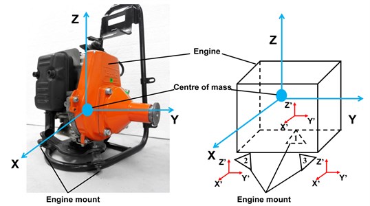
The existing engine mounting system of the grass trimmer, as shown in Fig. 1, consists of three rubber mounts installed below the engine at equally spaced and at specific installation angles. Several prior studies have focussed on the reduction of the hand-arm vibration (HAV) effect for the grass trimmer users. Ko et al. [1] minimised the HAV in the petrol-driven grass trimmer by decreasing the acceleration transmissibility of the engine to the handle. The HAV of the electric grass trimmer is reduced using the tuned vibration absorber, optimally positioned along the grass trimmer shaft [2]. In addition, the imposing node technique has also been applied to the grass trimmer shaft in order to reduce HAV [3]. This study also shows that the main direction of the HAV of the grass trimmer is along the crankshaft axis of the engine and indicates that vibration reduction of the engine’s crankshaft axis is necessary. The exposure of the grass trimmer workers to HAV will likely cause secondary Raynaud’s phenomena and carpal tunnel syndrome in the long term. This is because the total level of vibration on the handle of the grass trimmer, as determined by Ko et al. [1], exceeds the daily vibration exposure limit. The level of vibration of the handle is directly related to the rolling vibration of the engine. Therefore, it is necessary to minimise the roll vibration of the grass trimmer engine.
In the past, optimisation of the engine mount mainly focused on the reduction of the total excitation forces transmitted to the rigid frame [4-6]. Spiekermann et al. [7] shifted the natural frequency of resonance away from the excitation frequency by changing the location, orientation and stiffness of the engine mounts. Tao et al. [4] minimised the vertical force transmitted from the marine engine to the floor in order to reduce the structure-borne noise contributed by the bending wave. Furthermore, Kaul and Dhingra [8] minimised the total transmitted force to the frame by optimising the parameters of stiffness, and locations and orientations of the mounts. The vibration transmitted from the powertrain to the chassis of city buses was reduced by two methods, namely the elastic axis and the torque roll axis uncoupling methods [6]. Ooi and Ripin [9] showed that the orientation angle and the installation location of the engine mount can be included in the study of an engine mounting system, using the transformation matrix together with the measured properties of each individual mount along the compression and shear directions.
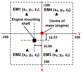
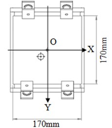
Fig. 1The global coordinate system and local coordinate system for the grass trimmer engine
The installation locations and the orientation angles have significant influence on the engine mounting system performance and these must be considered in the design of this system [10]. Kaul et al. [5] optimised the motorcycle engine mounting system by minimising the transmitted force to the frame by varying of the mount parameters. Tao et al. [4] in their optimisation work incorporated the location and orientation angles of the engine mount together with the frequency-independent properties of the individual mount. Prior studies have also investigated the effect of the engine mount orientations on the global dynamic stiffness, whereby the resonant frequency of the dynamic stiffness decreases when the engine mount orientation changes from 0° to 90° [11]. This finding is significant and introduced the way for future optimisation of engine mounting systems. Yu et al. [10] highlighted the importance of frequency-dependent dynamic stiffnesses and damping of various engine mounts, including elastomeric, passive hydraulic, and semi-active and active mounts. The viscoelastic behaviour of the isolator is the main characteristic for attenuating the engine vibration and it is integrated into different mechanical designs and applications [12-13]. Recently, the effects of frequency-dependent mount properties on the dynamics of powertrain motions have been studied using different methods [14]. Such frequency-dependent properties of the engine mount have also been accounted for in the minimisation of force transmissibility for the engine mounting system [15]. Such published results showed that optimisations based on frequency-independent properties overestimated the attenuation level of the force transmissibility, whereas and the use of the frequency-dependent characteristics of the engine mount produces results that are closer to the measured values. Installing isolators at the engine and handle of a hand tractor has resulted in the reduction of vibration by 50.9 % and 29.8 % at the respective locations [16]. In addition, installing three-stage vibration isolators in the hand tractor, one at the engine, one at the handle bar and one at the handle, resulted in 50-60 % reduction of handle vibration under stationary conditions [17]. These studies clearly showed that the isolators affected the handle-isolator transmissibility since vibration transmissibility is one of the most important aspects for the characterisation of the effectiveness of the vibration isolation system [18].
This study focuses on the use of the frequency-dependent characteristics of the mount of the actual grass trimmer engine. Minimisation of the rolling vibration acceleration of this engine is targeted by searching for the optimum mount location and orientation angle, based on the frequency-dependent stiffness and loss factor characteristics. This study is important since vibration attenuation of both the engine and the handle can be achieved by optimum design of the engine mounting system, thereby minimising long-term handle vibration effects for the grass trimmer operators.
2. Methodology
This study focuses on the minimisation of the rolling axis vibration of the grass trimmer engine. The actual input engine force and the generated engine moment are measured to allow construction of the input force matrix, used subsequently to the drive the optimisation process, realistically representing the actual vibration level of the grass trimmer.
2.1. Mathematical model
The mathematical model for the rolling vibration of the engine, which includes the orientation angles and location of the engine mount, must first be defined. The engine is assumed to be a rigid mass, where all the engine particles are moving with the same velocity. The vibration of the rigid frame of the engine is ignored because it is negligible compared to the vibration of the engine itself [10]. There are two coordinate systems involved in the modelling: a local coordinate system and a global coordinate system. The dynamic properties of the individual engine mount are referred to as the individual mount properties (which also include the engine block), whereas the installation of the engine mounts for the whole engine mounting structure is referred to as the engine mounting system properties. The center of mass of the engine is considered to be the origin of the global coordinate system (Fig. 1); in this coordinate system the - and -axes are parallel to the floor while the -axis is perpendicular to it. The -axis that aligns with the crankshaft rotation axis is considered to be the roll axis. The global coordinate system is labelled as and the local coordinate system as , as in Fig. 1. There are three units of engine mounts in the original grass trimmer design, labelled as 1, 2 and 3, as shown in the schematic of Fig. 1.
The grass trimmer engine and the mounting system are modelled with six degrees of freedom (DOF) and represented by the following equation of motion:
where is the rigid mass matrix of the engine which consists , mass of engine and , ,..., , moment of inertia along the particular axis and is given by:
is the translational and rotational displacement vector of the centre of mass, is the frequency-dependent complex stiffness matrix which consisting of translational stiffness and rotational stiffness. is defined as the stiffness modulus including the stiffness properties and the loss factor of the isolator as . At here, is the frequency-dependent stiffness and is the frequency-dependent loss factor which representing the damping properties in the complex stiffness method [19]. is the vector of excitation forces and moments on the system and is the angular frequency.
Let and . Therefore, the response of the system can be derived as:
The receptance function is the complex ratio of output response to the input force (Newland, 1989) and can be written as:
Since the rolling vibration is the angular acceleration of the rolling axis of the engine and the main parameter of this analysis, the accelerance (ratio of acceleration to force), , is calculated in accordance to the ISO 10846-1:2008 standard, as follows:
Each individual engine mount is associated with a three-dimensional complex stiffness matrix, , comprising of frequency-dependent compression and shear stiffnesses in accordance to:
where , , is the frequency-dependent stiffness and , , is the frequency-dependent loss factor along the three orthogonal directions of the respective local coordinate system. 1, 2, 3 which denoted numbering of the engine mount. These local complex stiffness properties of each individual engine mount are transformed to the global coordinate by using the Euler’s transformation matrix in accordance to:
After the transformation is applied, the dynamic properties for each individual mount part in the global coordinate system become:
where , , ,..., represent the individual mount stiffness along the particular axis in the global coordinate system. is the transpose matrix for the Euler transformation matrix. The dynamic properties for the whole engine mounting system are the summation of the product of each individual dynamic property in the global coordinate system with its respective position vector, expressed as:
where is the position matrix of each individual engine mount and is the number of the engine mount.
The vector of excitation forces and their moments is given by:
where , and are the excitation forces acting on the centre of mass of the engine in the -, - and -directions, respectively, while , and are the corresponding moments about the principal axes of the engine-mount system. These measured excitation forces and moments from the engine are inserted in Eq. (3) (as shown in a subsequent section), to calculate the response from the grass trimmer.
2.2. Experimental measurement of the engine force and moment
The excitation forces and moments of the engine are determined experimentally for use as input in Eq. (10). Since the angular acceleration along the -axis (rolling axis), which is parallel to the crankshaft axis of the engine, is the main interest in this study, and given the fact that the primary vibration is due to [20], the input parameters of and are neglected.
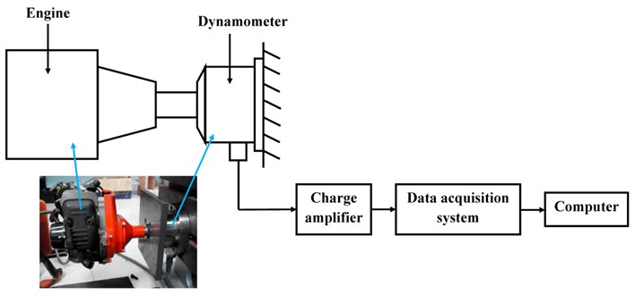
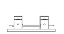
A four-component Kistler dynamometer (type: 9272) was used for measuring the three orthogonal excitation forces and the moment about the -axis, with the engine mounted vertically on the dynamometer at the fixed table, as shown in Fig. 2. The measurement is carried out at a speed of 6000 revolutions per minute (rpm).
Fig. 2Experiment setup for measuring the excitation forces and moment
2.3. Experimental measurement for rolling vibration acceleration of the engine to the handle
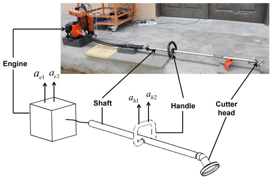
The rolling vibration angular acceleration of the handle and the engine are the main parameters that determine the effectiveness of the system in reducing the rolling vibration of the handle. The instruments used for experimental measurements include the data acquisition system and analyser (IMC, type: CS-3008-1) and two accelerometers (Kistler, type: 8776A50). The grass trimmer used in this study and the measurement setup are shown in Fig. 3. The accelerometers are placed on the engine and on the handle to measure the engine’s input acceleration and the handle’s transmitted output angular acceleration. The angular vibration is measured indirectly using two accelerometers that allow the measurement of the relative acceleration of the two locations (engine and handle), as the difference of the experimentally measured accelerations divided by the distance between the accelerometers, as illustrated in Fig. 3. In Fig. 3, and are the accelerometers at the engine and and are the accelerometers at the handle.
Fig. 3Measurement setup for the angular acceleration transmissibility from the engine to the handle
3. Minimisation of handle vibration response
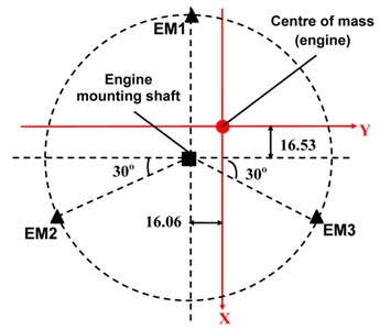
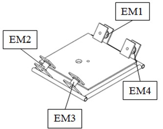
The optimisation process was carried out to search for the optimum orientation angle and the location of each engine mount for attaining minimum angular acceleration transmissibility about the engine’s rolling axis, at its maximum operating speed of 6000 rpm. The optimisation is subjected to the constraints of the engine mount location and orientation. Fig. 4(a) shows the original mounting layout. The three engine mount units used in this study are labelled as EM1, EM2 and EM3 in the figure. The three engine mounts are installed at angles of 120° apart. The centre of mass of the engine is considered as the reference coordinate or origin of the system at location (0, 0, 0). The origin of the mounting layout is offset from the centre of mass of the engine by 16.53 mm and 16.06 mm. The original position and orientation angle of each engine mount are measured and listed in Table 1.
Table 1Original positions and orientation angles of three engine mounts units from grass trimmer
Engine mount | Positions (mm) | Orientation angle (°) | ||||
EM1 | –68.64 | –16.06 | –84.12 | 0 | –30 | 180 |
EM2 | 59.12 | –89.82 | –84.12 | 30 | 30 | 60 |
EM3 | 59.12 | 57.70 | –84.12 | –30 | –30 | –60 |
For the improved design, a four-point mounting system is selected. The location constraints are defined based on the allowable space in the current engine support frame. The design and location constraints for the new engine mounting system is presented in Fig. 4(b), where the location constraint is set such that the engine mount can exist anywhere within a volume of 100×100×5 mm3. In addition, each engine mount is also subjected to the same orientation constraints of –90° to 90° for each orientation angle. The optimisation solver fmincon from MATLAB is used with the optimisation algorithm set to interior-point. fmincon is one of the optimisation approach which used to find a constrained minimum of a scalar objective function from the combination of several design variables. The design condition using fmincon usually subjected to several constrains. fmincon always start the searching using an initial estimate value. After obtained the local minimum for the objective function, the program will continue search to obtain the global minimum for the particular objective function. Optimisation using fmincon is generally referred as constrained nonlinear optimization. In this study, the objective function and the respective constraints are presented in Table 2.
Fig. 4Layout of the engine mounting system for the grass trimmer
a) Original system
b) New four-point mounting system
Table 2Objective function and the respective constraints
Objective function | Minimise mean peak () |
Subject to | |
–90° , , 90° | (Orientation constraints) |
–0.1 , , , 0 | (Location constraints in - and -axes) |
0, , , 0.1 | (Location constraints in - and -axes) |
–0.085 , , , –0.080 | (Location constraints in -axis) |
At here, is the angular acceleration along the -axis and , , are the individual orientation angle of engine mount along -, -, and -axes respectively. The layout for , , can be referred in Fig. 4.
4. Results and discussion
4.1. Input force and moment from grass trimmer
The excitation forces , , and moment at an engine operating speed of 6000 rpm (100 Hz) are measured and shown in Fig. 5. From this figure, the excitation forces measured at the -, - and -axes at the operating speed are found to have peak values of 45 N, 43 N and 76 N, respectively. This shows that the excitation force in the vertical direction (-axis) is the highest, while the other forces acting in horizontal plane (- and -axes) are approximately the same. In Fig. 5(b), there is the second peak for the excitation force in the -direction. This second peak is due to the second harmonic of the reciprocating motion, as discussed by Tao et al. (2000). The variation of the engine’s measured moment about the -axis is shown in Fig. 5(d). Its maximum value is measured to be 4.16 N.m. Force and moment values are used as the input excitation data for the calculation described in the section that follows.
Fig. 5Variational plots of measured input force versus frequency of the grass trimmer engine at 6000 rpm
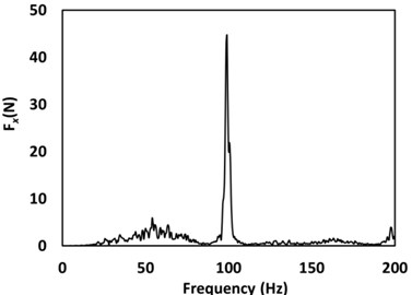
a)-direction
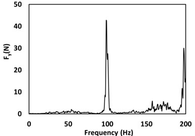
b)-direction
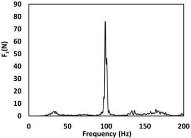
c)-direction
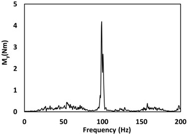
d) Measured moment about the -axis
Fig. 6Design of the new engine mounting system based on the optimum orientation angle and location values
a) Top view
b) Isometric view
c) Front view
d) Right view
4.2. Optimisation results
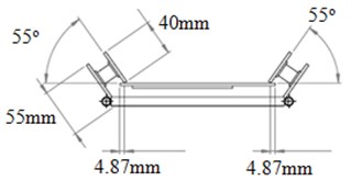
The results of the original and the optimised parameters are listed in Table 3. From Table 3, the peak value of angular acceleration of the rolling axis of the engine is reduced from 307 rad/s2 to 82 rad/s2 in the optimised system, representing a 73 % reduction. Each optimised engine mount has its dominant orientation angle aligning with the -axis, as shown in Table 3. Specifically, indicative values of 55°, 55°, 55° and –55° are recorded for engine mounts EM1, EM2, EM3 and EM4, respectively. The location of each optimised engine mount is observed to be symmetrical about the and axes as shown in Fig. 6, depicting the front, top, right and isometric views of the optimised design. The optimised engine mounting system parts are then fabricated and installed, as shown in Fig. 6, for validation purposes.
The system responses of the optimised and original systems are shown in Fig. 7. The peak acceleration response in the -direction reduces from 46 m/s2 to 12 m/s2 after the optimisation, an effective percentage reduction of 73 %, as shown in Fig. 7(a). For the acceleration response along the -direction, there is a reduction of 62 % from a value of 28 m/s2 to 10 m/s2. The reduction of the vibration is the smallest along the -axis, as shown in Fig. 7(c), noting a change in value compared to the original response from 48 m/s2 to 36 m/s2. The objective of this study was to minimize the vibration about the rolling axis of the engine by searching for the optimum engine mount parameters. The optimum results show that the highest percentage of vibration reduction is 73 %, with a noted reduction in rotational acceleration from 307 rad/s2 to 82 rad/s2, as shown in Fig. 7(d). These reduction levels are significant and are expected to reduce the vibration level of the handle. Such findings indicate the effectiveness of vibration reduction with the choice of the proper orientation angle and location of the engine mounts.
Table 3Comparison of the original and optimised parameters of the engine mounting system
Parameters | Original | Optimised |
Peak angular acceleration in -axis (rad/s2) | 307 | 82 |
Orientation angle for mount 1, (°) | 0 | 0 |
Orientation angle for mount 1, (°) | –30 | –55 |
Orientation angle for mount 1, (°) | 180 | 1 |
Orientation angle for mount 2, (°) | 30 | –2 |
Orientation angle for mount 2, (°) | 30 | 55 |
Orientation angle for mount 2, (°) | 60 | –2 |
Orientation angle for mount 3, (°) | –30 | –2 |
Orientation angle for mount 3, (°) | –30 | 55 |
Orientation angle for mount 3, (°) | –60 | –2 |
Orientation angle for mount 4, (°) | NA | –1 |
Orientation angle for mount 4, (°) | NA | –55 |
Orientation angle for mount 4, (°) | NA | 0 |
Location for mount 1, (m) | –0.069 | –0.099 |
Location for mount 1, (m) | –0.016 | –0.047 |
Location for mount 1, (m) | –0.084 | –0.085 |
Location for mount 2, (m) | 0.059 | 0.099 |
Location for mount 2, (m) | –0.090 | –0.051 |
Location for mount 2, (m) | –0.084 | –0.085 |
Location for mount 3, (m) | 0.059 | 0.099 |
Location for mount 3, (m) | 0.058 | 0.050 |
Location for mount 3, (m) | –0.084 | –0.085 |
Location for mount 4, (m) | NA | –0.099 |
Location for mount 4, (m) | NA | 0.048 |
Location for mount 4, (m) | NA | –0.085 |
4.3. Comparison of the rolling vibration for the existing and the newly proposed design of the engine mounting system
The rolling vibration at both the engine and the handle of the grass trimmer are measured at both the original and the optimised systems to demonstrate the practical application of an optimised design. Fig. 8 shows the measured rolling vibration of the original and optimised engine mounting system when the engine is operating at 6000 rpm. For the rolling vibration of the engine the peak rolling vibration is reduced from 44 rad/s2 to 31 rad/s2, as shown in Fig. 8(a). For the rolling vibration of the handle, the peak rolling vibration at 100 Hz is reduced from 18.5 rad/s2 to 6.6 rad/s2, as shown in Fig. 8 (b). The reduction in the rolling vibration for both the engine and handle justifies the effectiveness of the optimised system. Noted also is a second peak of 40 rad/s2 at 24 Hz in the optimised system. However, this is outside the operating speed of the engine. The vibration on the grass trimmer handle is caused by the rolling vibration of the engine. The rolling vibration of engine is subsequently transmitted to the grass trimmer handle and causes HAV. From Fig. 8, the results showed that the rolling vibration transmitted from the engine to the handle is reduced significantly. At the operating speed of 100 Hz, the rolling vibration transmissibility from the engine to the handle is 0.42 for the original engine mounting system and 0.21 for the new design. This shows that the rolling vibration transmission is reduced by 50 % in the new design of the engine mounting system.
Fig. 7Comparison plots of the Log translational acceleration response versus frequency for the original and optimised system (––– original system, - - - - optimised system)
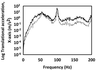
a)-axis
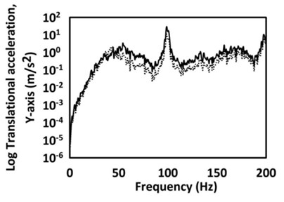
b)-axis
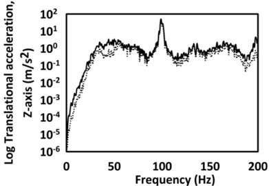
c)-axis
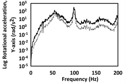
d) Rotational acceleration response along the -axis
Table 4Comparison of the mean angular acceleration transmissibility of the grass trimmer
Mean angular acceleration transmissibility | Percentage of reduction | |
Original system | Optimised system | |
1.661 | 0.420 | 75 % |
The mean angular acceleration transmissibility, for both the original and newly designed systems, is calculated over the measured frequency range. The results are summarised in Table 4. The mean angular acceleration transmissibility about the rolling axis is successfully reduced by 75 % from 1.661 to 0.420. This implies that the optimum engine mount parameters not only reduce the vibration about the engine rolling axis but also reduce the transmissibility of angular acceleration from the engine to the handle. Furthermore, the mean transmissibility of the optimised system has a value of less than unity, indicating that the vibration is not amplified when it is transmitted from the engine to the handle.
Fig. 8Comparison plots of the angular acceleration versus frequency of the a) engine, and b) handle, for the original and optimised systems for the grass trimmer
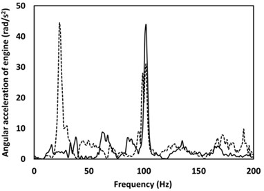
a)
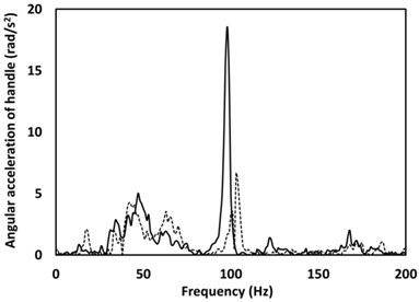
b)
5. Conclusions
The measured frequency-dependent properties of the engine mount are presented in the analysis of this work that also includes the optimisation of the new four-point mounting system. The optimum orientation angles and the installation locations of each individual mount are obtained based on the minimum angular acceleration in the rolling axis, which resulted in 73 % reduction in the elicited vibration level. The optimum parameters of this new design are used in the fabrication of the modified engine mounting system for the commercially available grass trimmer. The experimental measurement results showed 75 % reduction in the mean angular acceleration transmissibility from the engine to the handle of the grass trimmer.
References
-
Ko Y. H., Ooi L. E., Ripin Z. M. The design and development of suspended handles for reducing hand-arm vibration in petrol driven grass trimmer. International Journal of Industrial Ergonomics, Vol. 41, 2011, p. 459-470.
-
Ko Y. H., Lee X. M., Ripin Z. M. Tuned vibration absorber for suppression of hand-arm vibration in electric grass trimmer. International Journal of Industrial Ergonomics, Vol. 41, Issue 5, 2011, p. 494-508.
-
Ko Y. H., Ripin Z. M. Nodal control of grass trimmer handle vibration. International Journal of Industrial Ergonomics, Vol. 43, 2013, p. 18-30.
-
Tao J. S., Liu G. R., Lam K. Y. Design optimization of marine engine-mount system. Journal of Sound and Vibration, Vol. 235, Issue 3, 2000, p. 477-494.
-
Kaul S., Dhingra A. K., Hunter T. G. Two approaches for optimum design of motorcycle engine mount systems. Engineering Optimization, Vol. 37, Issue 3, 2005, p. 307-324.
-
Hafidi A. E., Martin B., Loredo A., Jego E. Vibration reduction on city buses: determination of optimal position of engine mounts. Mechanical Systems and Signal Processing, Vol. 24, 2010, p. 2198-2209.
-
Spiekermann C. E., Radcliffe C. J., Goodman E. D. Optimal design and simulation of vibrational isolation systems. Journal of Mechanical Design, Vol. 107, 1985, p. 271-276.
-
Kaul S., Dhingra A. K. Engine mount optimization for vibration isolation in motorcycles. International Journal of Vehicle Mechanics and Mobility, Vol. 47, Issue 4, 2009, p. 419-436.
-
Ooi L. E., Ripin Z. M. Impact technique for measuring global dynamic stiffness of engine mounts. International Journal of Automotive Technology, Vol. 15, Issue 6, 2014, p. 1015-1026.
-
Yu Y. H., Saravanan M. P., Nagi G. N., Rao V. D. Automotive vehicle engine mounting systems: a survey. Journal of Dynamic Systems, Measurement, and Control, Vol. 123, Issue 2, 2001, p. 186-194.
-
Ooi L. E., Ripin Z. M. Dynamic analysis of engine mounts at different orientations. Proceedings of SPIE 7522, Fourth International Conference on Experimental Mechanics, 2010, p. 752238.
-
Lu Y. C. Effects of viscoelastic properties of engine cover sealing system on noise and vibration attenuation. International Journal of Mechanics and Materials in Design, Vol. 3, 2006, p. 277-284.
-
Aly E. K., Anwar K., Abu B. O. Vibration isolation of a symmetric rigid plate using struts under static and dynamic axial excitation. International Journal of Mechanics and Materials in Design, Vol. 6, 2010, p. 257-267.
-
Park J. Y., Singh R. Role of spectrally varying mount properties in influencing coupling between powertrain motions under torque excitation. Journal of Sound and Vibration, Vol. 329, 2010, p. 2895-2914.
-
Ooi L. E., Ripin Z. M. Optimization of an engine mounting system with consideration of frequency-dependent stiffness and loss factor. Journal of Vibration and Control, 2014.
-
Tewari V. K., Dewangan K. N. Effect of vibration isolators in reduction of work stress during field operation of hand tractor. Biosystems Engineering, Vol. 103, 2009, p. 146-158.
-
Sam B., Kathirvel K. Development and evaluation of vibration isolators for reducing hand transmitted vibration of walking and riding type power tillers. Biosystems Engineering, Vol. 103, 2009, p. 427-437.
-
Tu Y. Q., Zheng G. T. On the vibration isolation of flexible structures. Journal of Applied Mechanics, Vol. 74, Issue 3, 2007, p. 415-420.
-
Jeong T., Singh R. Inclusion of measured frequency and amplitude dependent mount properties in vehicle or machinery models. Journal of Sound and Vibration, Vol. 245, Issue 3, 2001, p. 385-415.
-
Gupta K. N., Rao M. R. K. Torque roll axis and its influence on automotive engine mountings. Journal of the Indian Institute of Science, Vol. 44, Issue 3, 1962, p. 104-120.
About this article

The authors would like to acknowledge the Education Ministry, Malaysia and the Universiti Sains Malaysia for funding this project through the DE 2012 Grant 1002/PAERO/910350. The authors also acknowledge Mr. Wan Mohd Amri Wan Mamat Ali and Mr. Baharum Awang for their assistance in the experimental setup.
