Abstract
The basic theory and main features of operating modal analysis method have been elaborated, and then by using this method, the parameters of low-order natural characteristics of some wheeled and tracked self-propelled guns have been obtained. By two examples, the application of the operating modal analysis method for the development of self-propelled gun has been introduced. According to the result of operating modal analysis, for some wheeled self-propelled gun, “beat vibration” between the first-order natural characteristics and firing frequency of the gun has been identified, and further research indicates that the primary cause of the “beat vibration” is that the stiffness of the cradle is too weak which enlarges the vibratory response of the muzzle. With the reinforcement of the cradle, the testing result of firing indicates that the vibratory response of the muzzle is reduced obviously, and that the firing dispersion is much better than before. In order to certificate the accuracy of its dynamic model, for some tracked self-propelled guns, the natural characteristics of the whole gun through a comparison of the operating modal analysis and finite element calculation have been specified, and then according to the results of operating modal analysis, the dynamic model of the gun has been meliorated, and the natural characteristics of the gun by the finite element calculation are consistent with those by the operating modal analysis. This indicates that the model of the gun is correct with the vibratory response of the whole gun under seven running fire simulated, and that the error of vibratory response of the muzzle between firing testing and analog simulation does not exceed 15 %.
1. Introduction
The natural characteristics of the self-propelled gun have significant impact on its vibration response, dynamic strength, as well as firing dispersion [1]. So, it is important to master the natural characteristics of the guns to research its vibratory response and firing dispersion.
Due to its big mass and complex structure, it is difficult to obtain the natural characteristics of the self-propelled guns, for it is a big trouble both to ensure the exciting of whole system and to avoid partial overloading at the same time. By using the operating modal analysis method, its much bigger exciting energy and more uniform energy dispersion, can be used for obtain the natural characteristics of the self-propelled guns [2, 3]. For this method, the other advantage is that the exciting signals need not to be recorded and that the modal analysis can be done when the gun is firing [4]. So, in this paper, the operating modal analysis method is used to obtain the natural characteristics of some wheeled and tracked self-propelled guns, and according to the results of modal analysis, the firing dispersion of some wheeled self-propelled gun and the dynamic modeling and its validity of some tracked self-propelled gun are researched respectively, and the research result is, helpfully, of much use in the development of the self-propelled guns [5].
2. The operating modal analysis method
The modal parameters are identified from the response signals picked up when the structure is in working conditions or under environmental exciting, and the method is known as the operating modal analysis method [6, 7].
The basic idea of the operating modal analysis lies in the fact that the expressions of the cross-correlation function has the similar format with the impulse response function between the two response points, and that the modal parameters can be identified in the time domain after the cross-correlation function between the two response points has been obtained [8, 9]. If the exciting is unknown, the operating deflection shape frequency response functions (ODS FRF) can be used to identify the natural characteristics of the gun accurately [10, 11]. ODS FRF is a frequency response function calculated from response data of different points under the working conditions, with response signals of some points as the reference signals, and others as flow response signals. By calculating the cross-spectrum between the flow response signals and the reference response signals, the ODS FRF substitutes the square root of the spectral amplitude of the flow response signals with the cross-spectral amplitude, and retains the phase information of response data between different measurement groups in cross spectrum. Therefore, ODS FRF is constituted by combining self-spectrum amplitude of the flow response signals and cross-spectrum phase information of the flow response signals as well as reference response signals, and its expression is:
where: represents the cross-spectrum of the flow response signals and reference response signals; represents the self-spectrum of the flow response signals.
If the exciting spectrum is relatively flat in the vicinity of natural frequency, that means it is characteristic of the white noise stimulation, and that the fitting method of the frequency response function can be used to fit ODS FRF curve, and thus modal parameters can be obtained. The frequency response function matrix contains the frequency response function curve, stimulation Fourier spectrum and response Fourier spectrum. Frequency response function matrix elements can be expressed as:
where: represents Fourier spectrum of the response signal; represents Fourier spectrum of the stimulation signal; represents transfer function of incentive and response signal.
If stimulation in the vicinity of the natural modal meets the white noise stimulation conditions, the amplitude of the Fourier spectrum can be substituted by a constant:
From Eq. (2) the relationship between the response and the frequency response function can be:
By the above analysis, it is evident that the information of the structure’s modal parameters is included in the ODS FRF which has similar expression with frequency response function. Therefore, the frequency response function fitting method can be used in fitting the ODS FRF, and the modal parameters can be obtained.
3. The obtainment of the natural characteristics of self-propelled guns by using the operating modal analysis
The operating modal analysis has been used to obtain the natural characteristics of the wheeled self-propelled gun and the tracked self-propelled gun. The two kinds of guns have the similar structure forms, so, takes the tracked self-propelled guns as example to describe the process of testing.
During the testing, the self-propelled guns are parked on flat floor. When the preparation work is ready, start the engines for exciting, and the exciting process is: with the engineer having been started, raise the rotational speed of the engine from minimum to maximum gradually, hold on for 30 seconds at maximum rotational speed, then reduce the rotational speed to minimum gradually and take the engine shutoff [12]. In this process, the vibration of the gun includes forced vibration and free vibration, and the acceleration responses signals of all the measuring points are picked up and recorded.
The acceleration transducer from PCB Corporation has been used to pick up the vibration response of the gun, with its model number being 333B30, measuring range 50 g, and sensitivity 100±10 mV/g. The DP730 Mobilyzer portable signal analyzer from DATA PHYSICS Corporation has been used to record and analyze the acceleration signals. The Me’scope VES analysis software from Vibrant Technology Me’scope VES has been used to process data and calculate the transfer function. The lower-order natural characteristics of the gun has much more important influence to its vibration, so, obtaining the parameters of the natural characteristics within 100 Hz is the main purpose of this experiment. So, the analysis band width and the number of spectral lines of this experiment were 100 Hz and 800 respectively, the frequency resolution was 0.125 Hz, the window type was Hanning.
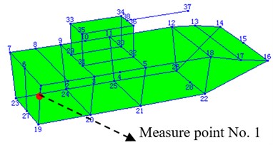
Since the number of the acceleration transducer is not adequate, the vibration response signals of all the measuring points cannot be picked up at the same time, so, for the same guns, the acceleration response signals of the chase, turret and recoiling parts should be picked up respectively, but they have to be integrated and analyzed together. Fig. 1 shows all the location of measuring points of the tracked self-propelled gun, the model which Fig. 1 shows is built up by connecting all the measuring points with straight-lines, at every measuring point, there has an acceleration transducer is fixed on surface of the gun with beeswax except No. 1 measuring point. There are two acceleration transducers installed at the No. 1 point: one to obtain the acceleration responses of the reference pint which is the benchmark for data integrating; the other to obtain the acceleration responses of the first testing point. Fig. 2 shows the testing site of the experiment.
Fig. 1Layout of testing points for the wheeled self-propelled gun
Then, the acceleration response of all the measuring points have been obtained firstly, the curves of the acceleration response decay with time obviously. Secondly, all the acceleration response need to be transformed according to the Fourier functions by the signal analyzer, self-spectrum functions () of all the measuring points and cross-spectrum functions between the flow measuring points and the reference measuring point were calculated. After all, the operating deflection shape frequency response functions (ODS FRFS) can be calculated according to the function Eq. (1) which was mentioned before. The parameters of the natural characteristics of the gun can be identified after the ODS FRFS was fitted with polynomial.
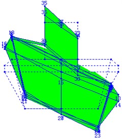
The results of the testing show the first three natural characteristics of the two guns which have different natural frequencies but the same modes shapes. Fig. 3 to Fig. 5 display the first three modal shapes of the guns, the first mode is the pitching mode, the second the up-and-down translation mode, and the third the roll mode.
Fig. 2Some photos of the experiment: a), b) The testing site of the experiment, and c), d) the acceleration transducer is fixed on the surface of the gun
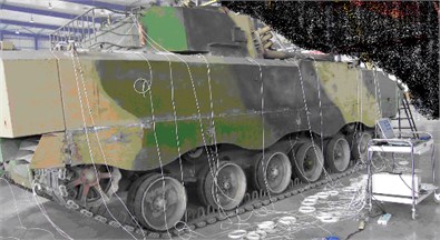
a)
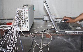
b)
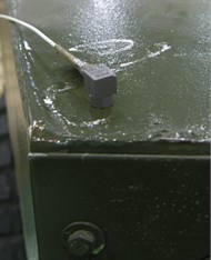
c)
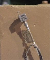
d)
Fig. 3The first-order mode of the self-propelled gun
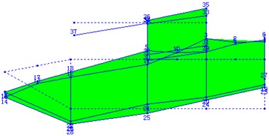
Fig. 4The second-order mode of the self-propelled gun
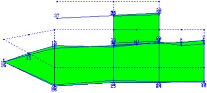
Table 1 shows low-order natural frequencies of the two kinds of guns. Clearly, when the modal shapes are identical, the natural frequency of tracked self-propelled gun is 1.83 to 2.34 times bigger than wheeled self-propelled guns, which indicates that the suspension stiffness of the tracked self-propelled gun is more rigid than that of the wheeled self-propelled gun, and that this is in full accord with the system composition and the structure design of the real guns.
Table 1The first three orders natural frequencies of the two kinds of guns
Modes order | Frequency / Hz | Vibration modes | |
Wheeled self-propelled gun | Tracked self-propelled gun | ||
1 | 2.90 | 5.32 | Pitch mode |
2 | 3.89 | 8.45 | Up-and-down mode |
3 | 5.2 | 12.21 | Roll mode |
Fig. 5The third-order mode of the wheeled self-propelled gun
4. The application of the operating modal analysis in firing dispersion research of some wheeled self-propelled gun
The firing dispersion of some wheeled self-propelled gun was once found unable to meet the design requirements, whereas the results of experiment modal analysis show that the first order natural frequency of the floating automatic is 11.5 Hz, which is too close with fire frequency 11.16 Hz. This may lead to “beat vibration” when the gun fires. The result of the testing shows the vibration displacement of muzzle has been enlarged seriously, and it also indicates that the “beat vibration” has already occurred. Further research indicates that the first order natural frequency has strong correlation with the stiffness of the cradle, So, in order to avoid the “beat vibration”, the stiffness of the cradle needs to be reinforced which can make the first order natural frequency of the cradle away from the fire frequency [13].
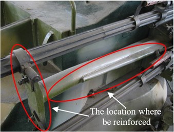
The stiffness of the tube and cradle have important impact on the natural characteristics of the floating automatic, for some wheeled self-propelled gun, the length and the wall thickness of the tube cannot be changed and there also has not enough space on the cradle for enhancing its stiffness. So, in order to enhance the stiffness of the floating automatic, the two parallel tubes have been fixed together with a cross stay, the position of the cross stay has been optimized and coupling with the nodal point of the tube, then, the cross stay has been extended and fixed with the cradle just as Fig. 6 shows.
Fig. 6The structure of the cradle before and after the stiffness was reinforced
With the reinforcement measures for the cradle stiffness taken, the node position of the first order mode shape shifts forward, the natural frequency is significantly increased, which is away from the firing frequency, and the mode displacement of the muzzle shift decreases which makes the vibratory response of the muzzle is reduced obviously, Fig. 7 shows the first order mode shape of the automatic machine after the stiffness of the cradle was reinforced.
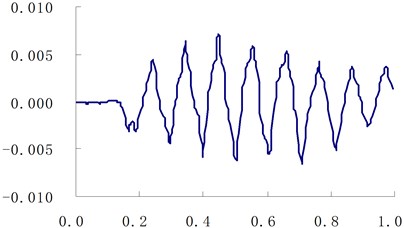
Then, when the gun was firing at shooting range, acceleration response of the muzzle was been tested with acceleration transducer which was fixed with hoop iron on the muzzle, the measuring range and the sensitivity of the acceleration transducer are 5000 g and 2 mV/g respectively, then, the vibratory displacement of the muzzle has been obtained through integral the acceleration response data twice, Fig. 8 shows the curves of muzzle vibration displacement at cross direction before and after the stiffness of the cradle has been reinforced, respectively. It is clear that the vibration displacement of muzzle drops significantly. The testing result of firing dispersion indicates that the firing dispersion of the gun has been raised from 6 mils to 3.7 mils, which can meet the design requirement of 4.5 mils. Table 2 shows the muzzle vibration displacement at cross direction and the first order natural frequency before and after the stiffness of the cradle has been reinforced.
Table 2The muzzle vibration displacement and the first natural frequency before and after the reinforcement of the cradle stiffness
Muzzle vibration displacement (mm) | Natural frequency (Hz) | |
Before reinforced | 25.0 | 11.5 |
After reinforced | 11.2 | 17.3 |
Fig. 7The first order mode shape of the automatic machine after the reinforcement of the cradle stiffness
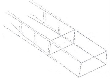
Fig. 8The test curves of muzzle vibration displacement before and after the reinforcement of the cradle stiffness
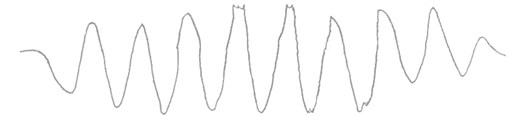
a) Before reinforcement

b) After the reinforcement
5. The application of operating modal analysis in dynamic model research of some tracked self-propelled gun
The dynamic model of the gun is helpful for forecasting its vibration response, but at first, the accurate model needs to be built up. In the process of gun modeling, it is an effective method to utilize the result of the operating modal analysis to validate and amend the dynamic model of the whole gun.
For some tracked self-propelled gun, with some proper simplification of the structure, the finite element model has been built up, just as Fig. 9 shows. Then the first three order natural characteristics of the gun have been obtained from analogy calculation and testing respectively. Those results are shown in Table 3. It was clear that the differences between the result out of the analogy calculation and that out of the testing are rather large, so, the parameters of the model should be amended according to the result of the testing. The main parameters include: (1) the stiffness coefficient of the suspension of the chase, (2) the stiffness coefficient of the elevating parts and rotating parts, (3) the equivalent mass of the gun, (4) the position of centroid position. After repeating the iterative calculation, the result of the first three order natural characteristics of the gun from analogy calculation accords with that from the testing, finally, just as Table 3 shows, which indicates that the dynamic model of the gun is correct.
Table 3The first three order natural characteristics of some tracked self-propelled gun
Order | Natural frequency / Hz | Vibration modes | ||
Before amending | After amending | Testing result | ||
1 | 6.20 | 5.61 | 5.32 | Pitch mode |
2 | 9.33 | 8.30 | 8.45 | Up-and-down mode |
3 | 14.16 | 12.75 | 12.21 | Roll mode |
The vibratory response of the whole gun with a seven running fire has been calculated. Fig. 10 shows the response of displacement of the gun at some time. Fig. 11 and Fig. 12 show the curves of vertical and traverse vibration displacement of the muzzle at cross direction which has been obtained from the analogy calculation, Fig. 13 and Fig. 14 show the curves of vertical and traverse vibration displacement of the muzzle at cross direction from testing. Just as those figures show, the error of vibration displacement of the muzzle between the analogy calculation and the testing does not exceed 15 %, which indicates that the accuracy of the dynamic model of the gun can meet the requirements for the development of the gun.
Fig. 9The dynamic finite element model of some tracked self-propelled gun
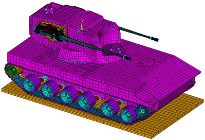
Fig. 10The vibratory response of the gun at some time
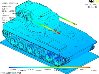
Fig. 11The calculation curve of muzzle vibration displacement at vertical direction (unit: m,s)
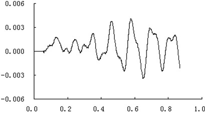
Fig. 12The calculation curve of muzzle vibration displacement at traverse direction (unit: m,s)
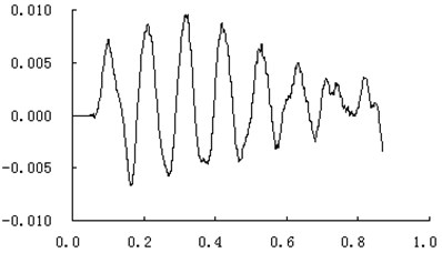
Fig. 13The testing curve of muzzle vibration displacement at vertical direction (unit: m,s)
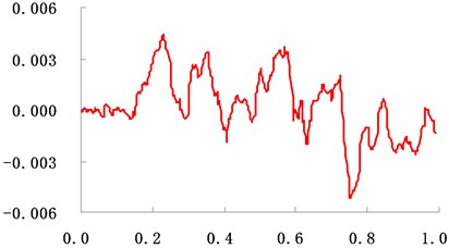
Fig. 14The curve of muzzle vibration displacement at traverse direction (unit: m,s)
6. Conclusions
The basic theory of operating modal analysis method has been specified. Following this method, the natural characteristics of some wheeled and tracked self-propelled guns have been obtained. For the first three orders, they have the identical modal shapes, and the frequencies of the tracked self-propelled gun are 1.83 to 2.34 times greater than the wheeled self-propelled guns, due to the fact that the stiffness of the suspension of the tracked self-propelled guns is much more rigid.
According to the result of operating modal analysis, for some wheeled self-propelled gun, the “beat vibration” between the first-order natural characteristics and firing frequency of the gun has been identified. And further research indicates that the “beat vibration” is the principal cause of the poor performance of the firing dispersion of the gun. So, the stiffness of the cradle needs to be reinforced which can make the first-order natural characteristics away from the firing frequency, to ensure that the “beat vibration” does not occur. Following the research finding and suggestions, with the stiffness of the cradle being reinforced, the firing dispersion of the gun has raised up from 6 mils to 3.7 mils.
According to the result of operating modal analysis, for some tracked self-propelled gun, with the iterative correction of some main model parameters and iterative calculation, the result of the first three order natural characteristics of the gun from analogy calculation agrees with the result from the testing, finally. Then, the vibratory response of the whole gun with a seven running fire has been calculated, and for the vertical and direction vibration displacement of the muzzle at cross direction, the error between the analogy calculation and the testing does not exceed 15 %, which shows that the accuracy of overall gun dynamics modeling has been significantly improved.
References
-
Ding Fa-qian Dynamics of Tracked Armored Vehicle Suspension System. National Defense Industry Press, Beijing, 2004, p. 1-10, (in Chinese).
-
Luz E., Wallaschek J. Experiment modal analysis using ambient vibration. The International Journal of Analytical and Experimental Modal Analysis, Vol. 7, Issue 1, 1992, p. 29-39.
-
James G. H., Carne T. G. Modal parameter extraction from large operation structures using ambient excitation. Proceeding of the 14th International Modal Analysis Conference, Society for Experimental Mechanics, 1996, p. 77-83.
-
Desforges M. J., Cooper J. E., Wright J. R. Spectral and modal parameter estimation from output-only measurements. Mechanical System and Signal Processing, Vol. 9, Issue 2, 1995, p. 169-186.
-
Wang Bao-yuan, Liu Peng-ke, Heng Gang, et al. The operating modal analysis experimental technique used for self-propelled gun. Acta Armamentarii, Vol. 30, Issue 7, 2009, p. 853-856, (in Chinese).
-
James G. H., Care T. G. The natural excitation technique (NEXT) for modal parameter extraction from ambient operating structure. The International Journal of Analytical and Experimental Modal Analysis, Vol. 10, Issue 4, 1995, p. 260-277.
-
Chiang D. Y., Cheng M. S. Modal parameter identification from ambient response. AIAA Journal, Vol. 37, Issue 4, 1999, p. 513-515.
-
Ruotolo R., Storer D., Taddeucci L. Development of a technique to determine the modal characteristics of structures using response data. Proceedings of the 15th International Modal Analysis Conference, Society of Experimental Mechanics, 1997, p. 704-710.
-
Hermans L. Auweraer H. V. Modal testing and analysis of structures under operational conditions: industrial application. Mechanical Systems and Signal Processing, Vol. 13, Issue 2, 1999, p. 193-216.
-
Yang Wei, Feng Pei-en Experiment modality analysis on metal belt type continuously variable transmission based on ambient stimulation. Chinese Journal of Mechanical Engineering, Vol. 39, Issue 4, 2003, (in Chinese).
-
Jin Xin-can, Sun Shou-guang, Xing Hong-lin, et al. operating modal analysis of a high speed passenger car. Journal of the China Railway Society, Vol. 25, Issue 3, 2003, p. 24-28, (in Chinese).
-
Schwarz Brian, Richardson Mark Scaling mode shapes obtained from operating data. IMAC, Vol. 2, 2003, p. 3-6.
-
Park Yong-Hwa, Park Youn-sik Structure optimization to enhance its natural frequencies based on measured frequency response functions. Journal of Sound and Vibration, Vol. 229, Issue 5, 2000, p. 1235-1255.
Cited by
About this article

