Abstract
Application of smart lubricants like magnetorheological (MR) fluids is always considered to be a promising field of realizing smart bearings with semi-active controllable capability. For bearings lubricated with MR fluid, the dynamic characteristics i.e. the stiffness and damping coefficients are important, while few studies have focused on this field. The present work adopts the Herschel-Bulkley model to describe the rheological behavior of MR fluid. The shearing-thinning effect incorporated in this model leads to different result compared to that from the Bingham model. Stiffness and damping coefficients of bearings lubricated with Newtonian fluid, Bingham fluid are calculated. Calculations show that shear-thinning effect has great influences on both static and dynamic characteristics of the journal bearing. Simulations of rotordynamics of a turbo-expander rotor with different bearing properties are performed to investigate the possibility of MR fluid as lubricants to control the behavior of rotor. Results show that MR fluids are applicable to change performances of the rotor system. Vibration amplitude suppression and critical speed alteration can be achieved by MR fluids.
1. Introduction
Hydrodynamic lubricated bearings are common in industry applications. Oil film produced by journal rotation is the key factor for generating forces to support the rotor and stiffness and damping to affect the dynamic behavior of the whole rotor system. Theories and experiments both reveal that the one crucial property of the lubricant itself in determining the static and dynamic characteristics of the bearing is its viscosity, along with thermoelastic effects, surface deformation, solid/fluid interaction, etc. In most industrial applications, common lubricants like oil are usually considered to have constant viscosities at constant temperature. Change of some factors like temperature and pressure can lead to the change of viscosity, but it is passive and uncontrollable. Modern applications, however, often require the rotor system to be ‘smart’, meaning that its performance could be controlled to meet various working conditions. Bearings lubricated with smart materials are therefore studied, aiming to actively adjust the stiffness and damping the bearing provided thus to control the behavior of the whole rotor system.
Because of their quick response and reliability, electrorheological (ER) fluid [1, 2] and magnetorheological (MR) fluid [3-7] are mostly used as smart lubricant. Without external electric field or magnetic field (off state), both fluids can be treated as Newtonian fluids. When external electric or magnetic field is applied, these two fluids exhibit viscoplasticity, categorizing them as non-Newtonian fluids. The alteration of viscosity in two different states could thus be used to actively control both static and dynamic behavior of hydrodynamic bearings. However, since the application of ER fluid requires very high currents and the yield stress of it at on state is relatively low, MR fluid is more applicable.
The Bingham model has been mainly used to describe the rheological behavior of lubricants. [3-5, 7, 8]. This model holds that the viscoplastic material behaves as a rigid body at low stresses but starts to flow as a viscous fluid at a threshold level of shear stress. Bingham model is firstly used to model grease lubricants which possess similar rheological behavior as ER and MR fluids. Studies were first carried out by Cohen and Oren [9] and Milne [10] to investigate grease lubricated bearings both experimentally and analytically. Pseudo-plastic cores in the oil film were demonstrated. Based on the Bingham theory, Wada et al. [8] developed a general theory to describe the core behavior in a finite length bearing and then applied to a one dimension situation. Tichy [7] proposed a simplified Bingham-based explicit Reynolds equation to model behavior of Bingham fluid in thin films, and then applied it to journal bearing and squeeze film damper. Zhang et al. [2] numerically studied a journal bearing lubricated with ER fluid by using the Bingham model, and concluded that the apparent viscosity and yield stress together determined the bearing behavior at high shear rates. Nikolakopoulos [1] studied a ER fluid lubricated bearing experimentally and analytically in a macroscopic way without discussing the rheology in oil film, and concluded that ER fluid could be used as smart bearing lubricant to control vibration. Kim and Seireg [11] carried out a thermohydrodynamic analysis of slider and journal bearings with Bingham lubricant, observing that the shear zone thickness was significantly smaller than the oil film thickness. Zhang [12] performed a TEHD analysis of a non-Newtonian fluid lubricated journal bearing with the power law model. He found that the shear-thinning effect decreased the oil film pressure while at the same time lowered film temperature. MR fluids are also applied in other types of bearings like hydrostatic bearing and thrust bearing. Hessbelch and Abel-Keilhack [5] used MR fluid in hydrostatic bearing to maintain a constant bearing gap for various payloads thus overcomes the disadvantage of this kind of bearings. Bouyahis and Hajjam [13] adopted the generalized Reynolds equation to describe non-Newtonian flow in a tilting-pads thrust bearings. Static parameters such as load capacity, friction torque and power loss were calculated. More recently, Gertzos et al. [4] and Bompos and Nikolakopoulos [3] investigated the rheological property and static characteristics of MR fluid lubricated bearing with CFD codes. Gertzos et al. [4] showed the three-dimensional rheological phenomenon in the bearing oil film. Urreta et al. [14] compared behavior of bearing lubricated with ferrofluid and MR fluid experimentally and numerically, concluding that ferrofluid was not appropriate for a smart bearing for lack of enough MR effect while MR fluid achieved good performance in controlling at low journal speed. Průša and Rajagopal [15] assumed a ER fluid with no yield stress and then used two material model for the constitutive relationships of Cauchy stress tensor. They established a full three-dimensional ER fluid model and found that behavior in three dimension differed from that in one or two dimension.
Bingham model assumes that the viscosity remains constant when shear stress exceeds yield stress. Experiments [16, 17] show, however, for common ER and MR fluids, viscosity decreases as shear rate increases. To incorporate this phenomenon a more general Herchel-Bulkley (HB) model is introduced. Wang et al [18] studied ER and MR fluids using the HB model. Their experimental results show that in low magnetic field strength, ER and MR fluids behave like Bingham fluid while in high magnetic field they behave like HB fluid, showing the effect of either shear-thinning or shear-thickening. Amalraj [19] analyzed a pressurized thrust bearing lubricated with MR fluid using HB model, taking into consideration of inertia effect. He concluded that high HB model numbers enhanced the bearing performance, and the fluid inertia effect was only significant when HB model numbers were low. Hewitt and Balmforth [6] developed a general viscoplastic lubrication theory with HB model and applied it to bearing and washboard instability of a plate, achieving good agreement with experiments.
In rotordynamics, dynamic characteristics such as stiffness and damping of the bearing is crucial for the performance of the whole rotor system. Researches [2-4, 7, 14] on ER/MR fluid lubricated bearings mainly focus on static behavior of the bearing i.e. load capacity, eccentricity and attitude angle etc., few consider the dynamic behavior of the smart bearings. In the present work, rheological, static and dynamic behavior of a MR fluid lubricated bearing is studied. Calculations of Bingham model and HB model are compared, showing distinct property in lubrication. Rotordynamic analysis is carried out on a turbo-expander rotor system. Results of this study could be used in designing smart journal bearings lubricated with ER or MR fluid.
2. Formulation of the problem
2.1. Fundamental equations
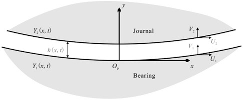
In order to simplify analysis and calculation, (1) the MR fluid is assumed to be incompressible; (2) body forces such as gravity are ignored, and (3) variables (pressure, strain, stress, etc.) along axial direction are treated as constant. Under these assumptions, in the oil film coordinate system shown in Fig. 1, continuity and momentum equations of the lubricants can be written as:
where is the velocity profile, is the fluid pressure, is the shear stress, and , are directions defined in the oil film illustrated in Fig. 1. Boundary conditions are:
in which subscripts 1 and 2 denote the inner surface of the bearing and the surface of the shaft, respectively, and is the coordinate of the boundary surface.
Fig. 1Geometry of part of the oil film of a journal bearing
Integrating the momentum equation with respect to , the following equations are obtained:
On the other hand, integrating the momentum equation from surface 1 to surface 2, the relationship between and can be found:
where is the thickness of the gap between the two surfaces. Eqs. (1), (3) and (4) apply to both liquid and core regions.
The Herschel-Bulkley model can be represented as:
where is the shear stress, is the yield stress, is the shear rate, and , are model constants. If , Eq. (4) becomes the expression of Bingham model with the viscosity; if , the fluid is shear thickening; if , the fluid is shear-thinning. According to Eq. (5), in the pre-yield region, is multi-valued, which may introduce mathematical difficulties. Hewitt and Balmforth [6] introduced a way to avoid this by using the inverse of Eq. (5):
where indicates . In the present work, this method is adopted, and on previous assumptions, .
In order to simplify the inclusion of HB model into the momentum equation, the following dimensionless form of variables are introduced:
Then Eqs. (3), (4) and (6) can be transformed into dimensionless form as:
wherein is the Bingham number defined as the ratio of yield stress to viscous stress. In the present model, takes the form:
Integrating Eq. (10) using boundary conditions Eq. (2) leads to:
Integrating continuity equation in Eqs. (1) with respect to then to , the following equation is obtained:
where is flux at , and:
Eq. (12) and Eq. (13) constitute a pair of algebraic equations to solve for and given , , and . In the problem of hydrodynamic bearing, however, is usually not prescribed, so more equations are needed to close this problem.
2.2. Oil film boundary condition
The following periodic condition is usually implemented as the oil film boundary condition:
where integral region is the whole circumference. This is essentially the Sommerfeld boundary condition, which has been proved to be far from reality because the oil film cannot sustain large negative pressure due to cavitation. In the present work, a more reasonable Reynolds boundary is applied. Reynolds boundary states that at some point in the oil film (somewhere near the minimum oil film thickness), the pressure gradient and pressure reduce to zero simultaneously, and the negative pressure region is simply set to zero pressure. The Reynolds boundary condition, therefore, can be represented as:
in which denotes the point at which both pressure and pressure gradient are zero. Eqs. (16) introduce two new equations and a new unknown variable . Now Eqs. (12), (13) along with Eqs. (16) can be solved for , , and .
2.3. Bearing geometry
The variation of oil film thickness is crucial for the formation of hydrodynamic pressure. With journal center eccentricity , the film thickness takes the form:
At each position in direction, a local coordinate system is established on the stationary surface of the bearing, as illustrated in Fig. 1. In this coordinate system, and . A more detailed sketch of geometric relations between journal and bearing is shown in Fig. 2 for deduction of and . Velocity at every point on surface 2 is composed by three parts , and that take the form:
the physical meaning of which are velocity due to journal rotation, attitude angle change (journal precession) and eccentricity change, respectively. Considering geometric relations, expressions of and at every point on the journal circumference are:
where:
Fig. 2a) Bearing geometry with journal speed ωj, eccentricity e, b) is the detailed view of the oil film geometry corresponding to Fig. 1
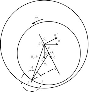
a)
b)
After nondimensionalizing quantities in Eq. (7), Eqs. (19) are substituted into Eq. (12), (13) and (16) to solve for the pressure distribution in the oil film.
2.4. Oil film force and dynamic coefficients
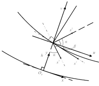
Applying the Reynolds boundary condition, oil film force is simply calculated with integral from to . For simplicity, oil film force and dynamic coefficients are first calculated in coordinate system and then transformed to the fixed bearing coordinate system . Relative positions of the two systems are illustrated in Fig. 2. In the system, oil film forces are obtained from pressure integrals:
where is the dimensionless length of the bearing. Stiffness and damping coefficients in the system are calculated by definition:
where is the rate of change of the attitude angle , and is equal to the precession rate . system leads system by angle , so and are transformed to and in the following way:
where is the transformation matrix.
3. Numerical results of MR bearing characteristics
3.1. Static characteristics
Equations listed above are solved numerically. First, Eqs. (12) and (13) are solved for and using assumed flux . Then is solved iteratively based on Reynolds boundary condition Eqs. (16), where is the point at which . Every value of is used to solve Eqs. (12) and (13) in the first step and the iteration goes on. When values all four unknowns are converged, the static condition of the bearing is determined. Investigation of bearing with constant load is also carried out by finding out suitable eccentricity and attitude angle. Therefore when , , and are determined, Newton-Raphson method with Aitken acceleration is applied to simultaneously solve for and at different rotating speed.
A journal bearing with radius 0.03 m, length 0.06 m and clearance 9×10⁻⁵ m is used in this work for analysis. Selection of values of parameters , and in the HB model results in models of Newtonian fluid (, ), Bingham fluid (, ) and viscoplastic fluid (, ). In the Newtonian fluid model, is actually the dynamic viscosity . For reference, the value of is set to 42×10-3 from the Lord MRF-122EG technical data [20] in the above three models.
3.1.1. Rheology in oil film
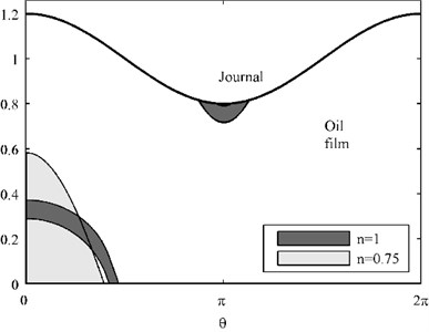
Rheology forms in oil film of Bingham model and HB model is presented in Fig. 3. Different values of (1, 0.75) representing Bingham and shear-thinning HB model are selected to investigate rheological behavior and oil film pressure with 42×10-3, 100 Pa and the journal rotating at speed 500 rpm. Results with relatively high (0.8) and low (0.2) relative eccentricity are shown in Fig. 3 and Fig. 4.
Fig. 3Core formation and dimensionless oil film pressure, ε= 0.8
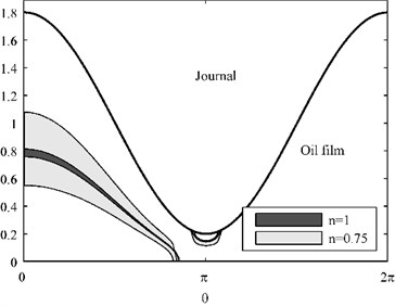
a) Core region of Bingham and shear-thinning HB fluids
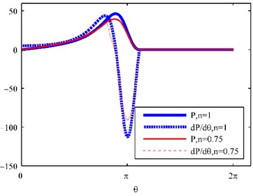
b) Dimensionless pressure and pressure gradient
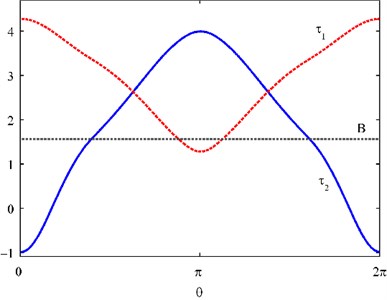
Whether the eccentricity is high or low, HB model predicts a larger core region, whereas the pressure is generally lower. Possible reason for this is the apparent viscosity affected by . When , apparent viscosity decreases as the shear rate increases, therefore with the same shear rate, shear stress of the HB model is lower than that of the Bingham model, which results in a larger non-yield region. On the other hand, pressure mainly depends on viscosity when shear rate is constant. Lower apparent viscosity produces lower oil film pressure. Cores are primarily formed in two typical regions in both situations. One is the area near the bearing surface where . The other is a small area near , where the oil film thickness reaches its minimum. Core formation and location are determined by bearing surface stress , journal surface stress and Bingham number B in the following four conditions:
a) , and . Floating core.
b) , and . No core formed.
c) , . Core attached to the bearing surface.
d) , . Core attached to the journal surface.
Fig. 4Core formation and dimensionless oil film pressure, ε= 0.2
a) Core region of Bingham and shear-thinning HB fluids
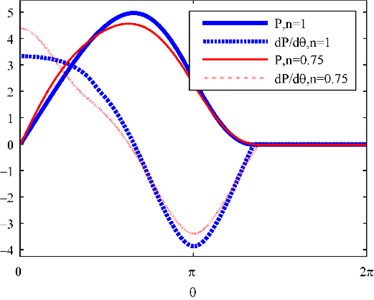
b) Dimensionless pressure and pressure gradient
Fig. 5Dimensionless shear stress of bearing and journal surfaces
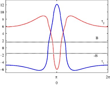
a) Relative eccentricity 0.8
b) Relative eccentricity 0.2
Fig. 6Core region and oil film pressure of lubricants with yield stress 100 Pa and 1000 Pa
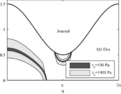
a) Core region
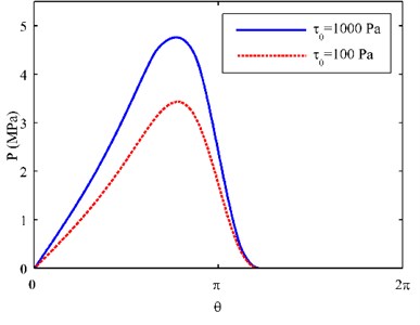
b) Oil film pressure distribution
Fig. 5 illustrates the dimensionless shear stress at oil film surfaces in the situation of 0.75 and (a) 0.8, (b) 0.2, which are corresponding to the 0.75 situation in Fig. 3(a) and Fig. 4(a), respectively. It is obvious core formation depends on the relative values of , and . Comparing Fig. 3 and Fig. 4, we can conclude that eccentricity is the main factor in determining the shape of the core region, whereas the magnitude of yield stress determines the area of core region.
Fig. 6 shows the core region and oil film pressure of two Bingham lubricants with 42×10-3, yield stress 100 Pa and 100 Pa, at journal speed 500 rpm, and a moderate relative eccentricity 0.5. It again demonstrates that when other conditions are identical, higher yield stress produces larger core region and oil film pressure.
3.1.2. Load capacity and journal locus
Properties of the MR fluid are affected by several factors including viscosity of the carrier fluid, ratio of the carbonyl powder, average and distribution of the radii of the carbonyl particles, etc. Therefore five kinds of lubricants are adopted here for comparison: (1) a typical Newtonian lubricant with viscosity 12×10-3 Pa∙s (12 cP), corresponding to 12×10-3, 0 and 1 in the HB model, (2) a Newtonian lubricant with viscosity 42 cP, representing the MR fluid at off state, (3) a Bingham fluid with parameters in HB model 0.1, 1000 and 1 to simulate the MR fluid at on state, and (4) a weak shear-thinning model with 0.1, 1000 and 0.92, and (5) a strong shear-thinning model with 0.1, 1000 and 0.75.
Fig. 7Load capacity vs. eccentricity of the five lubricants at 500 rpm journal speed
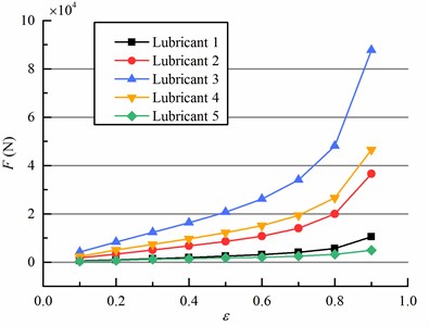
Fig. 8Journal center loci of bearings lubricated with the five lubricants
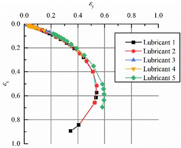
Load capacity is changed when lubricants are either Bingham or HB fluid. Oil film forces of the five situations with journal rotating at 500 rpm and eccentricity 0.1-0.9 are shown in Fig. 7. Comparison of lubricant 1 and 2 demonstrate that higher viscosity produces higher oil film force for Newtonian fluid. Non-Newtonian lubricant 3 without shear-thinning effect possesses the highest load capacity. The strong shear-thinning lubricant 5 exhibits the lowest load capacity, whereas the weak shear-thinning lubricant 4 produces a relatively high force. Reason for this is that when shear rate is relatively high, the apparent viscosity is low, resulting in low load capacity. Fig. 8 shows the journal center loci with journal speed from 20-660 rpm. At the lowest rotating speed 20 rpm, journal with lubricant 1 has the greatest eccentricity while journal with lubricant 3 has the smallest one. And journal with lubricant 4 incorporating strong shear-thinning effect holds a larger attitude angle. The center locus of journal with weak shear-thinning lubricant 5 is almost the same as that of the Bingham lubricant. As the speed increases, the five loci seem to converge to a certain locus, but values at the same speed are distinct.
3.2. Dynamic characteristics
Viscosity and rheological behavior not only affect the load capacity but also the stiffness and damping properties of the bearing. The previous five lubricants are also adopted to illustrate the stiffness and damping alteration.
3.2.1. Stiffness coefficients
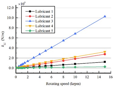
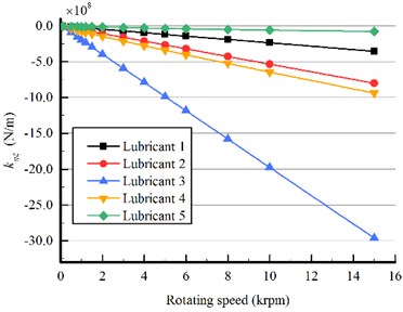
At low journal speed (i.e. rpm < 100), because of the larger eccentricity, bearing with lower viscosity (lubricant 1) provides greater stiffness.
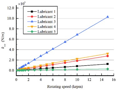
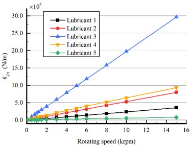
Generally speaking, as journal speed increases bearings with larger viscosity (lubricants 2 and 3) provide larger stiffness. Both direct and cross stiffness show this tendency as illustrated in Fig 9 and Fig. 10. The strong shear-thinning lubricant 5 still shows unique characteristics. Similar to its load capacity trend, the stiffness coefficients of the bearing lubricated with lubricant 4 are relatively low and increase most slowly with journal speed compared to those of the other lubricants.
Fig. 9Direct stiffness of bearings lubricated with the five lubricants, journal speed 20-660 rpm
a) Vertical stiffness coefficient
b) Horizontal stiffness
Fig. 10Cross stiffness of bearings lubricated with the five lubricants, journal speed 20-660 rpm
a) Cross stiffness coefficient
b) Cross stiffness coefficients
It is obvious from Fig. 9 and Fig. 10 that as journal speed increases, differences of the absolute magnitude of the four stiffness coefficients also increases, and stiffness of lubricants with no or weak shear-thinning effect (lubricants 3 and 4) increases more rapidly. At journal speed 8000 rpm, difference between lubricant 2 and 3, representing the off and on state of the MR fluid, in the vertical direct stiffness reaches to 5.4747×1081.4772×108 3.9975×10⁸ N/m, an increase as high as (3.99751.4772)×107(1.4772×10⁷)170.6 %. This phenomenon suggests that as journal speed increases, contribution of the rheological effect to bearing stiffness becomes more significant.
3.2.2. Damping coefficients
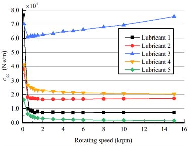
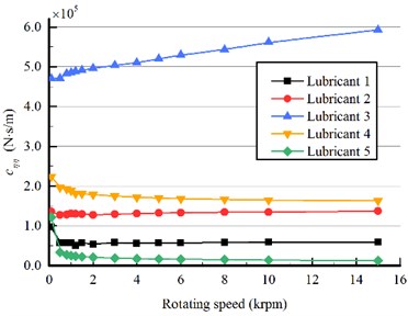
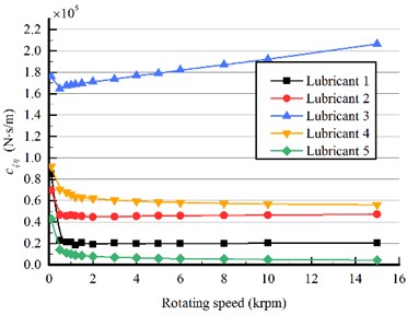
Damping properties of the bearings lubricated with the five lubricants show trends similar to the stiffness while still bear differences, as shown in Fig. 11 and Fig. 12. Large eccentricity still dominates the damping behavior when journal speed is low. And higher viscosity (lubricants 2 and 3) still provides greater damping as rotating speed increases. Unlike the stiffness coefficients, however, when some journal speed is passed (about 2000 rpm), the influence of rheological behavior on damping tends to be constant, except the Bingham model (lubricant 3). And the differences between the damping coefficients of other four lubricants almost cease to change with the journal speed. This phenomenon suggests that the shear-thinning effect, whether strong or weak, has great effects on damping coefficients.
Fig. 11Direct damping of bearings lubricated with the five lubricants, journal speed 20-660 rpm
a) Vertical damping coefficient
b) Horizontal damping coefficient
Fig. 12Cross damping of bearings lubricated with the five lubricants, journal speed 20-660 rpm

a) Cross damping coefficient
b) Cross damping coefficient
From Fig. 9-Fig. 12, different effects of rheological behavior on stiffness and damping can be observed. Generally speaking, as journal rotating speed increases, divergence of values of the stiffness coefficients increases significantly, while those of damping coefficients remain almost constant when some speed is passed.
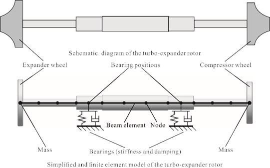
4. Simulation of a rotor system using MR bearings
The vibration behaviors of a turbo-expander rotor is simulated in this section. Turbo-expanders, main part of which is a high speed rotator, are often used to provide cooling capacity for many industrial systems, such as air separator, power generation, etc. The turbo-expander rotor includes three main parts, i.e. the expander wheel, the compressor wheel and the connecting shaft, as illustrated in the schematic diagram in Fig. 13. In this study, shapes of the two wheels are simplified since we ignore the effects of the working fluid on the rotor system, replacing them with disks having identical masses. Rotordynamic analysis is carried out in commercial codes NASTRAN, and the finite element (FE) model of the rotor system is shown in Fig. 13. The shaft is discretized with beam elements; the two wheels (disks) are model with mass element and bearings are modeled using CBEAR elements, incorporating the stiffness and damping effects of the bearings.
Fig. 13Structure and FE model of the turbo-expander rotor system
4.1. Eigenfrequency analysis
Eigenfrequencies (critical speeds) are first calculated to estimate the typical behavior of the system. Since the rotor constantly runs under 15000 rpm, eigenfrequencies below 250 Hz (i.e. 15000 rpm) are considered here. Table 1 lists the eigenfrequencies of the rotor lubricated with the aforementioned five lubricants.
Table 1Eigenfrequencies of the rotor with bearings lubricated with five lubricants (Hz)
Order | Lubricant 1 | Lubricant 2 | Lubricant 3 | Lubricant 4 | Lubricant 5 |
1 | 49.7 | 26.4 | 18.4 | 33.0 | 90.2 |
2 | 76.0 | 40.1 | 20.0 | 42.9 | 91.6 |
3 | 141.6 | 131.4 | 131.1 | 131.4 | 144.1 |
4 | 166.1 | 159.7 | 156.1 | 160. | 179.4 |
Figs. 9-12 show that at speeds above 1000 rpm magnitudes of stiffness and damping coefficients of the five lubricants descends in the order of lubricant 3, 4, 2, 1 and 5. The eigenvalue analysis shows, however, this is not necessary the case for the eigenfrequencies. Due to the asymmetry of the stiffness and damping of the bearings, the order 1 and order 2 are two tilting mode frequencies. For lubricants 3 and 5, their first two frequencies are relatively close, because near those frequencies stiffness in the and direction and damping in the and direction are close. Moreover, the inequality of the masses of the two disks make the rotor an asymmetric one, therefore there are two different bending mode frequencies which correspond to the third and fourth order of the rotor eigenfrequencies. Unlike the two tilting frequencies, the bending frequencies are less changed by the properties of different lubricants. Reason for this is that bending behaviors mostly depend on the stiffness and internal damping of the rotor itself while the rigid tilting modes frequencies are determined by the supporting stiffness and damping.
The higher bending frequencies (compared to tilting frequencies) also suggest that the stiffness of the shaft is larger than that of the supporting bearings. Therefore before the rotor reaches it’s first bending critical speed, it will first pass the tilting frequencies. Since lubricants 2-5 represent properties of MR fluids at on and off states, the changes in tilting mode frequencies implies that MR fluids are applicable for altering the rotor tilting frequencies to avoid fierce vibrations when passing through these frequencies.
4.2. Rotor speeding-up simulation
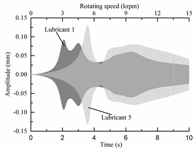
In actual applications rotor vibration is more crucial when the rotor is accelerating or decelerating passing various critical speeds. Theoretically the deceleration process is the inverse of the acceleration, so the speeding-up process is investigated in this study. The eccentricity is set to be 8×10⁻⁵ kg∙m on the expander wheel, representing an eccentric mass of 1 g at radius 80 mm. The process of the turbo-expander starting up in 10 seconds from 0 to 15000 rpm is simulated with speed-dependent bearing stiffness and damping, as calculated in section 3. Ordinary oil lubricant 1 is selected as a reference here to demonstrate the effects on MR fluid. Since vibration of the rotor is transferred to the turbo-expander base through the supporting bearings, vertical vibrations at the two nodes where bearings locate are measured. Fig. 14 illustrates the vibrations of the five lubricants during a start-up process in 10 seconds.
Fig. 14Speed-up vibrations of lubricants 2 to 5 compared with lubricant 1
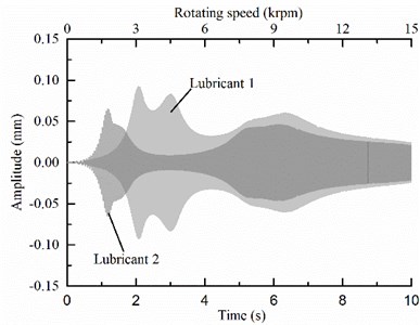
a) Lubricant 2 vs. lubricant 1
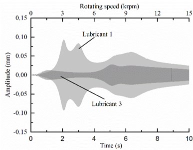
b) Lubricant 3 vs. lubricant 1
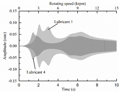
c) Lubricant 4 vs. lubricant 1
d) Lubricant 5 vs. lubricant 1
Peaks of curves in Fig. 14 corresponds to the eigenfrequencies of the various lubricants as listed in Table 1. For lubricants 3 and 5, because their first two tilting frequencies are very close, the two tilting peaks merge into one in Fig. 14 b) and d). Compared to ordinary oil lubricant 1, MR fluid at off state (lubricant 2) exhibits smaller amplitudes at tilting and bending critical speeds. The Bingham model MR fluid (lubricant 3) greatly suppresses the vibration at all speeds, especially at the tilting critical speeds. When shear-thinning effect is considered, behavior of the slightly shear-thinning MR fluid (lubricant 4) differs from the Bingham model, and the vibration-suppression effect becomes moderate. Fig. 14 d) shows that if the MR fluid strongly shear thins, it may fail to reduce the vibration amplitudes, but can largely alter the tilting frequencies.
The eigenfrequency and speeding-up analysis suggests the possible applications of MR fluid lubricants in rotor vibration control. First, since the shear-thinning effect of MR fluid is unavoidable, the Bingham model is inappropriate for modeling MR fluids, especially types strongly shear-thin. Second, for weak shear-thinning MR fluids, they can suppress the rotor vibration near critical speeds. Therefore when this type of MR fluids are used, during the accelerating or decelerating process, these fluids can be activated to avoid fierce vibration near critical speeds. Third, for strong shear-thinning MR fluids, they can greatly change the critical speeds, especially the tilting ones, even if they can barely control the vibration amplitude. This type of fluids thus are capable of avoiding severe vibrations near tilting critical speeds. For example, when we compare lubricant 2 and 5, which are the off and on states of the strong shear-thinning MR fluid, respectively, at about 2400 rpm, the fluid can be activated to avoid the tilting vibration. Then after 3000 rpm, the fluid can be deactivated to reduce shear-thinning effect, achieving a better performance.
5. Conclusions
Rheological, static and dynamic behavior of Newtonian, Bingham and shear-thinning fluid lubricated bearing is investigated. Herschel-Bulkley model is adopted to model these three kinds of fluid by adjusting the model parameters. Results show fluids with yield stress and shear-thinning effect used as lubricants alter the stiffness and damping characteristics of journal bearing. The following conclusions are drawn.
Area and locations of core regions are affected by the shear-thinning effect and magnitude of yield stress, but not the core patterns.
MR fluid as lubricant can increase the load capacity of the journal bearing only if the shear-thinning effect is not great.
MR fluid as lubricant has influences on stiffness and damping coefficients of the bearing in different ways. As journal rotating speed increases, increase in stiffness becomes more significant while increase in damping tends to stable values. Still, the influences greatly depend on the shear thinning effect of the MR fluid.
For strong and weak shear-thinning MR fluids, their applications are different. The strong shear-thinning type can be used to change critical speeds to avoid severe vibrations, while the weak shear-thinning type is good at suppressing vibration amplitudes.
Above conclusions suggest that in choosing MR fluids as journal bearing lubricants for vibration control and load capacity alteration, the shear-thinning effect of the MR fluid is important. Modelling MR fluid lubricated bearings with Bingham model without shear-thinning effect thus may lead to inaccurate results. Method and results presented in this work could be used for smart journal bearing designing where shear rate is high and the shear-thinning effect must be taken into consideration.
Since the MR fluid lubricated bearings have not yet been industrially applied, current commercial MR fluids, such as those manufactured by Lord Inc. which are mainly designed for dampers, may be inappropriate for lubricating. However, traditional oil lubricant, as pointed out by Bompos et al. [21], is also suitable for making MR fluids as carrier fluid. For lubrication applications several aspects must be considered like contamination, sedimentation, pumping, heating etc. To our knowledge, few publications studied these practical issues in MR fluid lubrication, therefore a test rig is underway to investigate these issues along with the verification of the current predictions.
References
-
Nikolakopoulos P., Papadopoulos C. Controllable high speed journal bearings, lubricated with electro-rheological fluids: an analytical and experimental approach. Tribology International, Vol. 31, Issue 5, 1998, p. 225-234.
-
Zhang Z., Zhu K.-Q. Characteristics of electrorheological fluid flow in journal bearings. Chinese Physics Letters, Vol. 19, Issue 2, 2002, p. 273-275.
-
Bompos D., Nikolakopoulos P. CFD simulation of magnetorheological fluid journal bearings. Simulation Modelling Practice and Theory, Vol. 19, Issue 4, 2011, p. 1035-1060.
-
Gertzos K. CFD analysis of journal bearing hydrodynamic lubrication by Bingham lubricant. Tribology International, Vol. 41, Issue 12, 2008, p. 1190-1204.
-
Hesselbach J., Abel-Keilhack C. Active hydrostatic bearing with magnetorheological fluid. Journal of Applied Physics, Vol. 93, Issue 10, 2003, p. 8441-8843.
-
Hewitt I. J., Balmforth N. J. Viscoplastic lubrication theory with application to bearings and the washboard instability of a planing plate. Journal of Non-Newtonian Fluid Mechanics, Vols. 169-170, 2012, p. 74-90.
-
Tichy J. Hydrodynamic lubrication theory for the Bingham plastic flow model. Journal of Rheology, Vol. 35, Issue 4, 1991, p. 477-496.
-
Wada S., Hayashi H., Haga K. Behavior of a Bingham solid in hydrodynamic lubrication. Bulletin of the JSME, Vol. 16, Issue 92, 1973, p. 422-431.
-
Cohen G., Oren J. Film pressure distribution in grease lubricated journal bearing. Transactions of ASME, Vol. 71, 1949, p. 555.
-
Milne A. A theory of rheodynamic lubrication. Kolloid, Vol. 139, 1954, p. 96-100.
-
Kim J., Seireg A. Thermohydrodynamic lubrication analysis incorporating Bingham rheological model. Journal of Tribology, Vol. 122, 2000, p. 137-146.
-
Zhang C. TEHD behavior of Non-Newtonian dynamically loaded journal bearings in mixed lubrication for direct problem. Journal of Tribology, Vol. 124, 2002, p. 178-185.
-
Bouyahia F., Hajjam M. Three-dimensional non-Newtonian lubricants flows in sector-shaped, tilting-pads thrust bearings. Proceedings of the Institution of the Mechical Engineers, Part J: Journal of Engineering Tribology, Vol. 220, Issue 4, 2006, p. 375-384.
-
Urreta H., Leicht Y., Sanchey A. Hydrodynamic bearing lubricated with magnetic fluids. Journal of Intelligent Material Systems and Structures, Vol. 21, 2010, p. 1491-1499.
-
Průša V., Rajagopal K. R. Flow of an electrorheological fluid between eccentric rotating cylinders. Theoretical and Computational Fluid Dynamics, Vol. 26, Issues 1-4, 2012, p. 1-21.
-
Becnel A., Hu W., Wereley N. Measurement of magnetorheological fluid properties at shear rates of up to 25000 s-1. Magnetics IEEE Transactions, Vol. 48, Issue 11, 2012, p. 3525-3528.
-
Wang X., Gordaninejad F. Study of magnetorheological fluids at high shear rates. Rheologica Acta, Vol. 45, Issue 6, 2006, p. 899-908.
-
Wang X., Gordaninejad F. Flow analysis of field-controllable electro- and magneto-theological fluids using Herschel-Bulkley model. Journal of Intelligent Mater Systems and Structures, Vol. 10, Issue 8, 1999, p. 601-608.
-
Amalraj I. Inertia effects in an externally pressurized thrust bearing using Herschel-Bulkley lubricants. American Journal of Computational and Applied Mathematics, Vol. 2, Issue 3, 2012, p. 79-85.
-
MRF-122EG Technical Data. Lord Inc., http://www.lord.com/?action=download&document_id= 2558&output=download.
-
Bompos D., Nikolakopoulos P. Experimental and analytical investigations of dynamic characteristics of magnetorheological and nano magnetorheological fluid film journal bearing. Proceedings of ASME Turbo Expo: Turbine Technical Conference and Exposition, 2014.
About this article

The authors wish to acknowledge the support from the National Basic Research Program of China (973 program) under Grant No. 2011CB706502 and the Funded Projects (USCAST2012-13) of SAST-SJTU Aerospace Advanced Technology Joint Research Centre in China.
