Abstract
High-damping rubber bearings, lead rubber bearings, and natural rubber bearings are often used to improve the seismic capacity of seismic isolation bearings. We present the results of an extensive series of experimental tests to identify the mechanical characteristics of these three types of seismic isolation bearings. Cyclic horizontal displacement tests, varying the test parameters of shear displacement amplitude axial load, and loading frequency tests were performed on each type of bearing. Bearing shear stiffness and damping properties were investigated in terms of the different test parameters. The ultimate tests consisted of monotonic shear loading to failure under axial loads, and tension failure tests of the bearings with bolted connections. Comparisons are made between experimental results and available analytical relationships for material and bearing properties.
1. Introduction
The laminated rubber bearing is now the most commonly-used device for seismic isolation. Accurately characterizing bearing mechanical properties is a very important aspect of the design process for an isolation system. Our experimental program was aimed at confirming and refining existing analytical models for this purpose [1].
Mineo Takayama (1995) [2] identified ultimate capacity with respect to the compressive, shear, and tensile tests for a natural rubber bearing. Nishio Koji et al. (1997) [3] reviewed tensile strain and yield strength with a tensile test for a high damping rubber bearing. In addition, the effect of anchor bolt tension was considered. Naoyuki Iwabe et al. (2000) [4] compared and analyzed the behavior characteristics of three types of laminated rubber bearing by using tensile tests. Ryuichi Kato et al. (2003 [5] studied variations in basic characteristics before and after tensile testing based on the thickness of a steel-stiffened plate.
In this study, an extensive series of tests on three types of seismic isolation bearing was carried out in order to fully identify their mechanical characteristics. A lead rubber bearing (LRB), high damping rubber bearing (HDRB), and natural rubber bearing (NRB) were studied. The characteristics of laminated rubber bearings were found to be dependent on displacements, repeated cycles, frequency, vertical pressure, temperature, the capability of shear deformation, and the vertical stiffness. In addition, using the same test specimen, monotonic shear failure tests and tensile failure tests were carried out to ultimate capacity.
2. Test conditions
Commonly used seismic isolators include laminated rubber bearings such as LRBs, HDRBs, NRBs, and steel bearings. After an earthquake, a steel bearing cannot regain its original shape, so the steel bearing should be replaced, which is uneconomical. We tested a laminated rubber bearing with excellent results in terms of damping and restoring force.
2.1. Bearing designs
A lead rubber bearing (LRB) consists of alternating layers of rubber and steel plates with one or more lead plugs that are inserted into holes. During an earthquake, an LRB lengthens the natural period of a structure due to the flexibility of the rubber. An LRB also restrains large displacement and decreases the magnitude of seismic stresses by the plastic behavior of its lead core, thereby providing a bilinear response (i.e., it adds hysteretic damping to the isolated structure) (Chung 2002) [6]. An HDRB modifies the rubber with enhanced dissipating properties, usually known as high damping rubber (HDR). The characteristic highly nonlinear stress-strain response of high damping rubber is affected by the type and amount of fillers, and by the amount of cross-linking (Oh 2010) [7, 8].
2.2. Test specimens
The specimens used in our tests were designed to meet the ultimate limit state for earthquakes, resistance for wind loads, and the use limit state that is designed by design compressive force and strain. The specimen is manufactured according to ISO 22762 (2005). The specifications of the test specimens are summarized in Table 1. Fig. 1 shows the shape of the test specimens. In Table 1, is the first shape factor and is the second shape factor. The shape factor equation is given as follows:
where is the diameter of the reinforcing steel plate, is the diameter of the inner hole, is the thickness of the rubber sheet, and is the number of rubber sheets.
Fig. 1Test specimens (LRB, NRB)
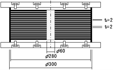
Fig. 2Compression-shear test machine
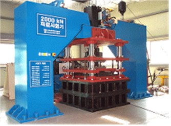
Table 1Specification of test specimens
Diameter of reinforcing steel plate (mm) | Diameter of inner hole (mm) | Total outer diameter (mm) | Number of rubber sheets () | Thickness of rubber sheet (mm) | Thickness of reinforcing steel plate (mm) | Shape factor | Shear modulus () | ||
LRB | 280 | 60 | 300 | 25 | 2 | 2 | 27.5 | 7.0 | 0.4 |
HDRB | 260 | 12 | 280 | 25 | 2 | 2 | 29.7 | 5.0 | 0.4 |
NRB | 280 | 60 | 300 | 25 | 2 | 2 | 27.5 | 7.0 | 0.4 |
2.3. Test machine
The laminated rubber bearing specimens were tested in the compressive/shear fatigue tester shown in Fig. 2. The maximum vertical load is 2,000 kN and the maximum horizontal load is 500 kN. The maximum horizontal velocity is 300 mm/s and the maximum horizontal displacement is ±200 mm.
3. Test conditions and method
3.1. Characteristic test
Three types of seismic isolation bearing were manufactured and the following dependence tests were performed: shear-strain dependency, compressive stress dependency, frequency dependency, temperature dependency, and repeated loading dependency. Fig. 3 shows the shear behavior shape of the laminated rubber bearing. In order to achieve the desired shear stiffness () and equivalent damping ratio (), a shear characteristic experiment was carried out as shown in Fig. 4. All tests were carried out at around 23 °C, and all specimens were tested under horizontal deformation with design vertical compressive stress. The horizontal displacement for the shear test is the vertical rubber thickness of the bearing. The bearings were subjected to cyclic shear displacement with 11 cycles. The results were calculated using average displacement data for 2 to 11 cycles.
Fig. 3Specimen under shear loading
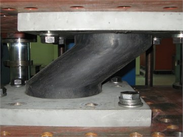
Fig. 4Shear properties test
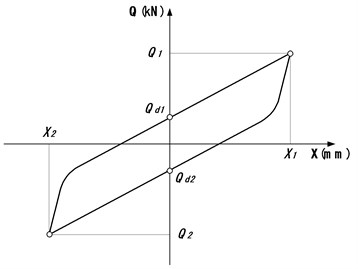
Fig. 5Ultimate shear properties
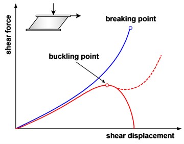
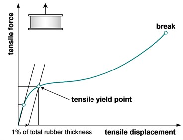
Fig. 6Tensile properties
3.2. Ultimate test
Ultimate shear and tensile tests were carried out using the two specimens of the LRB, HDRB, and NRB. In the shear failure test, horizontal displacement was increased to one side until the bearing failed in shear under compressive stress. The velocity of horizontal displacement is 0.5 mm/s. In the tensile failure test, the vertical displacement was increased with 0 % shear displacement at a constant velocity until the bearing failed in tension. The velocity range of the tensile displacement was limited to 0.05 to 0.1 mm/s for safety. The ultimate shear properties are shown in Fig. 5 and the tensile properties are shown in Fig. 6.
4. Test results
4.1. Characteristic tests
4.1.1. Compressive stress dependency
To identify the compressive stress dependence of the seismic isolation bearing, compressive-shear tests were carried out for various compressive forces. The tests were performed at a constant temperature of 23°C. Each specimen was tested under horizontal deformation with the design vertical compressive stress. The horizontal displacement for the shear test was the design shear displacement ( 100 %) which is same as vertical rubber thickness of the bearing. Each bearing was subjected to cyclic shear displacement with 11 cycles at a sine wave loading frequency of 0.5 Hz. The compressive stress conditions of this test were 0 %, 50 %, 100 %, 150 %, and 200 % of the design compressive force. The variation rate of shear stiffness () and equivalent damping ratio () are shown in Fig. 7. When the compressive stresses increase, the variation rate of the shear stiffness () for the LRB is about ±5 % and that of the HDRB is about ±7 %. The variation rate of the shear stiffness () of the NRB is about ±20 %. Analysis shows that the dependence of shear characteristics of the NRB on the compressive force is relatively larger than that of the LRB or HDRB. The equivalent damping ratio of the LRB is 33.9 %, that of the HDRB is 21 %, and that of the NRB is 3 %.
Fig. 7Effects of compressive stress dependency
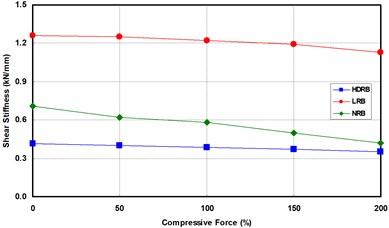
a) Shear stiffness
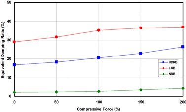
b) Equivalent damping ratio
Fig. 8Effects of shear strain dependency
a) Shear stiffness
b) Equivalent damping ratio
4.1.2. Shear-strain dependency
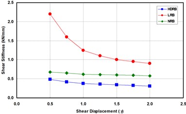
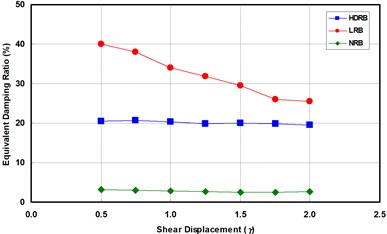
To identify the variation of shear stiffness and the equivalent damping ratio by the shear strain of the seismic isolation bearing, a compressive-shear test was carried out for various values of shear strain. The shear strain conditions of this test are 50 %, 75 %, 100 %, 125 %, 150 %, 175 %, and 200 %. The test was conducted, in order, from the smallest value of shear strain to the largest. The test method was same as that used in the compressive stress dependency test. The variation rate of the shear stiffness and the equivalent damping ratio were calculated using the results of the 100 % shear strain condition, and is shown in Fig. 8. When shear strains increase in the 50 % to 200 % range of shear strain, the shear stiffness and the equivalent damping ratio decrease. The variation rates of the LRB are the largest of all the seismic isolation bearings.
4.1.3. Frequency dependency
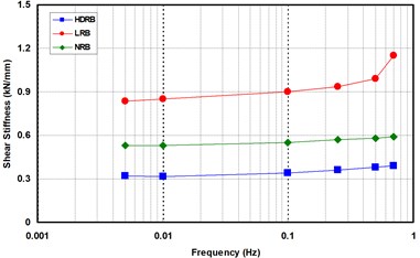
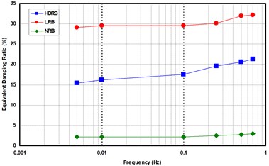
In order to identify the variation of shear stiffness and the equivalent damping ratio by frequency, a compressive-shear test was carried out at various frequencies. The frequency conditions of this test were 0.005, 0.01, 0.1, 0.25, 0.5, and 0.7 Hz, and the test was conducted in order from the lowest frequency to the highest. Testing at more than 0.7 Hz could not be conducted because of the velocity restriction of the test machine. The variation rate of shear stiffness and the equivalent damping ratio were calculated using the results from the 0.5 Hz frequency condition, and the results are shown in Fig. 9. When the frequency increases in the 0.005 to 0.5 Hz range, the shear stiffness and equivalent damping ratio increase. The variation rate of the HDRB is relatively large. On the other hand, the variation trends of the LRB dramatically change at more than 0.25 Hz.
Fig. 9Effects of frequency dependency
a) Shear stiffness
b) Equivalent damping ratio
Fig. 10Effects of temperature dependency
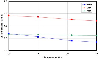
a) Shear stiffness
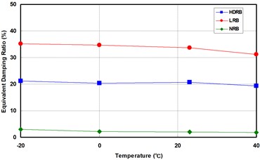
b) Equivalent damping ratio
4.1.4. Temperature dependency
In order to identify the variation of shear stiffness and equivalent damping ratio by temperature condition, compressive-shear tests were carried out at –20 °C, 0 °C, 23 °C, and 40 °C. The specimens were stored in a thermos-hygrostat for 3 days, were fixed on the test facility, and a constant temperature chamber was installed. To maintain temperature conditions, liquid nitrogen was used to create a low temperature and a hot blast heater was used to create a high temperature. The variation rate of shear stiffness and equivalent damping ratio were calculated by the result of 23 °C condition, and is shown in Fig. 10. When temperature increase in the –20 °C to 40 °C range on the temperature, the shear stiffness decreased. On the other hand, the equivalent damping ratio slightly decreased. The variation rates of shear stiffness of the HDRB are the largest of the seismic isolation bearings.
4.1.5. Repeated loading dependency
In order to identify the variation of shear stiffness and equivalent damping ratio by repeated loading, compressive-shear tests were carried out. The tests were conducted at around 23 °C. Specimens were tested under horizontal deformation with the design vertical compressive stress. The horizontal displacement for the shear test is the design shear displacement ( 100 %) which is same as vertical rubber thickness of the bearing. All specimens were subjected to cyclic shear displacement with 50 cycles with a sine wave loading frequency of 0.5 Hz. The shear stiffness and equivalent damping ratio of each deformation cycle were calculated, and the variation trend of shear characteristics by repeated cycle was identified. After the specimens were subjected to cycle shear displacement with 50 cycles, the specimens were cooled until the initial temperature of the specimens was re-measured in order to distinguish between shear characteristic variation by repeated loading and shear characteristic variation by increasing temperature. The shear characteristic variation of repeated loading is shown Fig. 11. The shear stiffness of the initial cycles (1 to 3) changed greatly, and the shear stiffness variation of the next cycles is small. The variation of shear stiffness of the LRB is smaller than that of the other specimens. And, the equivalent damping ratio of the LRB is the largest of the seismic isolation bearing types.
Fig. 11Effects of repeated loading dependency
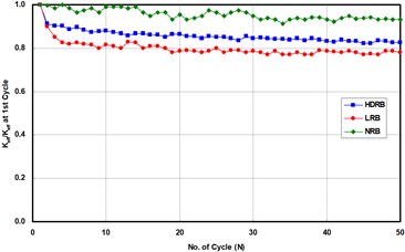
a) Shear stiffness
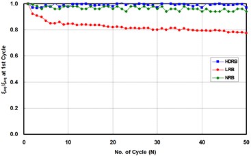
b) Equivalent damping ratio
4.2. Ultimate tests
4.2.1. Monotonic shear failure
The shear stress of the LRB is larger than the other laminated rubber bearing specimens. The shear stress increased rapidly around a shear strain value of 350 %. The final failure was caused at a shear displacement of 252 mm (a shear strain of about 500 %) with the result that the shear strain increased continuously. The secondary shape factor of the HDRB is lower than the other laminated rubber bearing specimens. The shear stress of the HDRB is slightly higher than the LRB and NRB. Shear failure did not occur at a shear displacement of 300 mm (a shear strain of 600 %). Buckling did not occur at a shear displacement of 260 mm, which is the outer diameter of the HDRB. The shear stress of the NRB is lower than the other laminated rubber bearing specimens, and the yield occurred at a shear displacement of 225 mm. After yield occurred, the shear displacement and shear stress increased continuously. The final failure occurred at a shear displacement of 242 mm, which is a shear strain of about 484 %. The shear failure displacement is lower than that of the LRB. The results of the monotonic shear failure test of the laminated rubber bearing are summarized in Table 2. The specifications of the laminated rubber bearing, failure stress, and failure strain are also shown in Table 2. Fig. 12 shows the results of the monotonic shear failure test of each specimen.
4.2.2. Monotonic tensile failure
In our tensile failure test, the initial tension yield stress of all specimens for a tensile strain of 1 % is about 2.0 MPa, and the value of the LRB (2.31 MPa) is the largest of all specimens. After the onset of yield behavior of the LRB, tensile failure occurred at a tensile strain of 312 % with tensile deformation and tensile failure stress is 5.20 MPa. The tensile failure stress of HDRB is lower than other specimens, but the tensile failure stress is somewhat large. The tensile strain of the HDRB is 352 % and the tensile stress is 4.72 MPa. Unlike the shear failure test, the tensile failure strain is the largest of all specimens for the tensile failure test. After the yield point was reached in the NRB, tensile failure occurred at a tensile strain of 356.4 % with tensile deformation and a tensile failure stress of 4.95 MPa. The results described above show that all specimens maintained tensile resistance until a tensile strain of 300 %. The results of our monotonic shear failure test of the laminated rubber bearing are summarized in Table 2. Fig. 12 shows the results of the monotonic tensile failure test for each specimen.
Fig. 12Monotonic shear failure
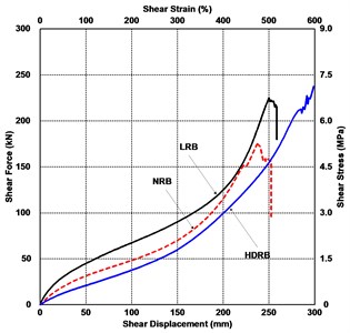
Fig. 13Monotonic tension failure
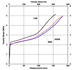
Table 2Results of ultimate tests
Specification of laminated rubber bearing | LRB | HDRB | NRB | ||
Height of isolator: (mm) | 192 | 192 | 192 | ||
Outer diameter of isolator: (mm) | 300 | 260 | 300 | ||
Total rubber thickness: (mm) | 50 | 50 | 50 | ||
First shape factor: | 27.5 | 29.7 | 27.5 | ||
Second shape factor: | 7.0 | 5.0 | 7.0 | ||
Monotonic shear failure | Failure stress (MPa) | 6.9 | 7.3 | 5.1 | |
Failure strain (%) | 504 | 600 | 484 | ||
Monotonic tensile failure | Tension stress (MPa) | Yield | 2.31 | 1.92 | 1.85 |
Failure | 5.20 | 4.72 | 4.95 | ||
Tension strain (mm) | Yield | 2.21 | 2.29 | 2.40 | |
Failure | 156.1 | 176.0 | 178.2 | ||
Failure strain (%) | 312 | 352 | 356 | ||
5. Conclusions
We performed various dependence tests and ultimate failure tests for the LRB, HDRB, and NRB isolation bearings. All of the bearings performed well over the large range of tests conducted. The results of our experimental investigation provide an extensive database for the confirmation and refinement of existing analytical models for isolation bearing properties. The variation of the characteristics of laminated rubber bearings with respect to the test condition is relatively large. The shear stiffness and equivalent damping ratio of the LRB is the largest of all specimens considered, and the energy dissipation capacity showed the best performance.
The fundamental bearing characteristics of shear stiffness and equivalent damping were studied in terms of shear strain, axial load, and the rate of loading. In general, we found that variations in the axial load and the rate of loading do not significantly affect bearing stiffness and damping properties for moderate shear strain levels. Our understanding of the failure mechanisms of seismic isolators has been enhanced by the various ultimate-level tests performed in this study. The ultimate-level shear failure tests showed a bearing shear strain in excess of 500 % before failure occurred. The tension failure tests achieved a bearing tensile strain in excess of 300 % before failure occurred.
Our results and conclusions can benefit the designers of isolation systems utilizing these types of bearings, and provide a greater understanding of, and confidence in, bearing properties and behavior.
References
-
Aiken I. D., Kelly J. M., Clark P. W. Experimental studies of the mechanical characteristics of three types of seismic isolation bearings. Proceeding 10th World Conference on Earthquake Engineering, 1992.
-
Takayama M. Ultimate capacity of natural rubber bearings used in seismic isolation system. Journal of the Architectural Institute of Japan, Vol. 1, 1995, p. 160-165.
-
Nishio K., Ishihara T., Yanagisawa N., Matsubayashi Y., Fujinami T. Study on tensile performance of base isolation devices. Part 2-tensile loading test of full sized high damping laminated rubber bearing. Summaries of Technical Papers of Annual Meeting, 1997, p. 529-530.
-
Iwabe N., Takayama M., Kani N., Wada A. Experimental study on the effects of tension for rubber bearings. 12th World Conference on Earthquake Engineering, Auckland, New Zealand, 2000.
-
Kato R., Oka K., Takayama M. The tensile tests of natural rubber bearings docused on the effects of the steel flange plates. ASEM Pressure Vessels and Piping Conference, 2003.
-
Chung G. Y., Ha D. H., Park K. N., Kim D. H. Experimental study on characteristics of LRB with low hardness rubber. Journal of the Korean Society of Civil Engineers, Vol. 22, Issue 6A, 2002, p. 1295-1307.
-
Oh J., Jung H. Y. An Experimental study for the shear property dependency of high damping rubber bearings. Journal of the Korean Society of Civil Engineers, Vol. 30, Issue 2A, 2010, p. 121-129.
-
Oh J., Lee J. U., Lim H. J., Kim H. O. Experimental evaluation of seismic performance for seismic isolation bearings. Conference and Annual Meeting of the Korean Society of Rheology, 2010.
-
Oh J., Lee J. U., Park K. N., Lee Y. H. Experimental study on ultimate capacity of seismic isolation bearings. Proceedings of the Earthquake Engineering Society of Korea Conference, Vol. 15, 2011, p. 231-234.
About this article

This research was supported by Basic Science Research Program through the National Research Foundation of Korea (NRF) funded by the Ministry of Education (2013R1A1A2059513).
