Abstract
In order to grasp the nonlinear characteristic of high-speed spatial parallel mechanism, the analysis of nonlinear characteristics for spatial parallel mechanism is investigated. The nonlinear elastic dynamic equation of 4-UPS-UPU high-speed spatial parallel mechanism is derived by kineto-elastodynamics theory, the dynamic equation is solved by numerical method, the nonlinear characteristic of the parallel mechanism is analyzed by phase diagram. Numerical results show that 4-UPS-UPU high-speed spatial parallel mechanism exhibits typical nonlinear characteristic during exercise, the factors, such as the motion trajectory of parallel mechanism, the material of driving limbs, the diameter of driving limbs and the mass of moving platform, are also have effect on nonlinear characteristics of parallel mechanism. Therefore the reasonable choice of the above factors can weaken the chaos motion. This researches provide important theoretical base of the chaos suppression for spatial parallel mechanism.
1. Introduction
The spatial parallel mechanism, which has advantages of high speed, high precision, good dynamic performance, high stiffness and tight construction, has been paid more attention [1, 2]. The stiffness of all parts in spatial parallel mechanism is different, for example, the stiffness of telescopic rod in driving limbs is far below the stiffness of moving platform. In high speed and high acceleration conditions, the spatial parallel mechanism is a rigid-flexible dynamic coupled system due to the geometry nonlinearity and coupling effect between rigid body motion and elastic deformation, and exhibits strong nonlinear characteristics. Therefore, in order to reveal and improve the dynamic behaviors, meet the needs of the design, the nonlinear characteristics of spatial parallel mechanisms must be investigated.
Up to now, the overwhelming majority of the analysis of elastodynamic behaviors for parallel mechanism are implemented within the linear theory framework [3-8], so the results obtained, which have bigger error [9-11], can not reflect the influencing factors of dynamic behaviors and actual dynamic behaviors, and then affect the dynamic optimal design. Besides, the existing studies are mainly focused on planar parallel mechanism, while less on spatial parallel mechanism. And that the study of the nonlinear characteristics of high-speed spatial parallel mechanism is quite few.
The elastic dynamics equation of 4-UPS-UPU 5-DOF high-speed spatial parallel mechanism (see Fig. 1) is derived by kineto-elastodynamics theory in this paper, the nonlinear characteristics are analyzed by Newmark method and phase diagram, the relationship between nonlinear characteristics and the factors, such as the motion trajectory of parallel mechanism, the material of driving limbs, the diameter of driving limbs and the mass of moving platform, are discussed.
2. Elastic dynamics model of spatial parallel mechanism
When defining the telescopic rod in driving limbs as elastomers, the nonlinear dynamic model of the 4-UPS-UPU high-speed spatial parallel mechanism is established as follows.
Fig. 1Mechanism diagram of 4-UPS-UPU
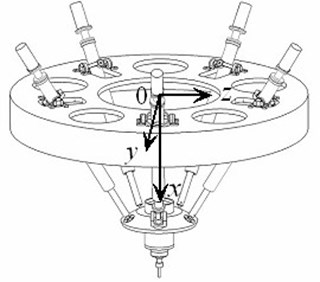
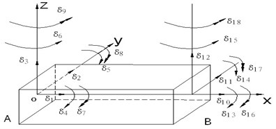
Fig. 2Model of beam element
2.1. Model of rectangle beam element
The rectangle beam element is adopted to model the spatial parallel mechanism, as shown in Fig. 2. The elastic displacement and elastic corner of arbitrary point on the axis of element are given by:
where , , are elastic displacement along , and axis, , are elastic angle around , and axis. is generalized coordinate vector for unit. , , and are displacement functions for unit.
The speed of arbitrary point on the axis of element is given by:
where , , are absolute velocity along , , direction, , , are rigid body velocity along , , direction; , , are elastic velocity along , , direction, , , are absolute angular velocity, rigid body angular velocity and elastic velocity around direction.
2.2. Dynamic model of rectangle beam element
2.2.1. Kinetic energy of beam element
The kinetic energy of beam element without considering the rotational energy can be expressed as:
where is the length of the beam element, is the mass density of the beam element, is the cross sectional area, is mass of the beam element, and , is polar moment of inertia of cross sectional area to axis.
2.2.2. Deformation energy of the beam element
The deformation energy of the beam element considering geometric nonlinearity is written as:
where is elastic modulus of tension and compression; is shearing modulus of elasticity; , , and are principal moment of inertia of unit cross section to , , axis.
2.2.3. Dynamic model of the beam element
Putting Eq. (11) and Eq. (12) into Lagrange equation, we can get:
where is the first-order derivative of unit’s generalized coordinate vector ; is the generalized force for unit.
From Eq. (13), the elastic dynamic model of beam element is given by:
where is generalized force array of element caused by external applied load, is force array of research element caused by connecting beam element, is the rigid inertial force array, is unit rigid body acceleration described by generalized coordinate vector, is the second-order derivative of unit’s generalized coordinate vector ; is the unit mass matrix, is the unit stiffness matrix with considering nonlinear factors.
2.3. Kinematic constraint equations
The kinematic constraint equations of spatial parallel mechanism are written as:
where , , is the coordinate of , is the elastic displacement vector of on driving limb, is the displacement of moving platform caused by elastic deformation, , and are unit (the unit on driving limb ) generalized coordinate vector in coordinate system .
2.4. Dynamic constraint equations
The dynamic constraint equations of spatial parallel mechanism are written as:
where , , , , , are the force and moment of moving platform caused by external applied load, , , , , , are the force and moment of moving platform caused by driving limbs, ,…, are the rotational inertia of moving platform, is the mass of moving platform, , ,…, are the acceleration of a moving platform, which contain 3 linear acceleration and 3 angular acceleration, , , are the second-order derivative of position coordinates; , and are the second-order derivative of Euler-angle coordinates.
2.5. Dynamic model of the spatial parallel mechanism
When assembling the dynamic model of each element, we can get the dynamic equation of each driving limb. The dynamic model of 4-UPS-UPU High-speed spatial parallel mechanism, which is obtained by combining the dynamic equation of each driving limb, kinematic constraint equations and dynamic constraint equations, is given by:
where is the mass matrix, is the gross damping matrix, is the stiffness matrix, is the generalized force matrix, is the generalized coordinate of system, is the transfer matrix from driving limb’s generalized coordinates to system’s generalized coordinates, is the relation matrix between displacement vector of moving platform and generalized coordinates of the system.
3. The analysis method of nonlinear dynamics characteristic
The elastic dynamic equation of 4-UPS-UPU high-speed spatial parallel mechanism is a variable coefficient differential equation, the equation is commonly solved by time-discrete method. In other words, the motion time of mechanism () is divided into a number of time units (), and the elastic dynamic equation, which is regard as a second-order differential equation with constant coefficients, is solved in each time unit. Newmark method is an effective method for solving this type of variable coefficient differential equations. The basic idea of the Newmark method is described as follows.
1) The method does not require any time to meet the motion equations, just require the time in discrete points to meet the motion equations.
2) The relationship between displacement, velocity, acceleration and time are assumed in the scope of .
The phase diagram, which describes the relationship between the vibration displacement and vibration speeds, is one of the commonly used method to study the nonlinear characteristics of the nonlinear dynamic system. In this paper, the nonlinear characteristics analysis of the 4-UPS-UPU high-speed parallel mechanism are achieved by combining the Newmark method with the phase diagram. That is applying Newmark method to solve nonlinear equations, getting vibration displacement and vibration velocity, and then applying phase diagram to analyze nonlinear characteristics.
When knowing the solution of dynamic differential equation in moment, the solutions of dynamic differential equation in moment obtained by Newmark method are written as:
where , , and are parameters related to the accuracy and stability.
In moment, the unknown quantity , and meet the system elastic dynamic equation, so we can get:
The Eqs. (18), (19) and (20) are the basic equations of the Newmark method. The equations of , and can be derived by the Eqs. (18), (19) and (20). The elastic displacement vector in moment can be obtained by Eq. (20), and the , in moment can be obtained by Eqs. (18) and (19), respectively.
The main steps of nonlinear dynamics analysis are as follows:
Step 1. Calculate the total system mass matrix , stiffness matrix and damping matrix .
Step 2. Give the initial value of , , .
Step 3. Select the time step , parameters and , and calculate the constants of integration:
Step 4. Form the effective stiffness matrix of system:
Step 5. Calculate the payload of time:
Step 6. Calculate displacement of time:
Step 7. Calculate acceleration and velocity of time:
Step 8. Draw the curve of changes with time, get the phase diagram.
4. Calculation and analysis of nonlinear characteristics for the parallel mechanism
4.1. The parameters of 4-UPS-UPU spatial parallel mechanism
In the 4-UPS-UPU spatial parallel mechanism, the distance between the first Hooke joint of the fixed platform and the center of the fixed platform is 780 mm, the other Hooke joints of the fixed platform distribute around the circle with a radius of 720 mm. The hinge points of moving platform distribute around the circle with a radius of 200 mm. The driving limbs are made of steel, mass density is 7.801×10³ kg/m3, elastic modulus = 2.1×10¹¹ Pa.
Shear modulus 8.0×10¹⁰ Pa, Poisson’s ratio is 0.29, the mass of moving platform is 36.64 kg. The length of oscillating rod in driving limbs is 0.76 m, the length of expansion link in driving limbs is 0.88 m. The moment of inertia of the moving platform are 0.948 kg∙m2, 0.81×10⁻⁸ kg∙m2, 0.56×10⁻² kg⋅m2, 0.66424 kg⋅m2, 1.166×10⁻⁷ kg⋅m2, 0.56×10⁻² kg⋅m2, 1.166×10⁻⁷ kg⋅m2 and 0.64 kg⋅m2, respectively.
4.2. Numerical example 1
The law of motion for 4-UPS-UPU spatial parallel mechanism is defined as (unit: s, m):
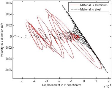
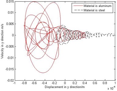
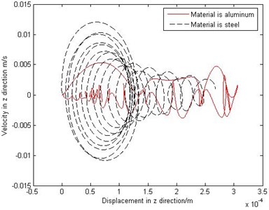
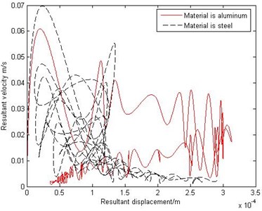
According to the given motion Eq. (21) of 4-UPS-UPU high-speed spatial parallel mechanism, when the material of driving limbs are steel and aluminum, the phase diagrams are shown in Fig. 3. From Fig. 3, the motion in the -axis direction is irregular and bounded, so its movement is in the form of chaotic motion, the motion in the -axis direction is regular and cyclical, but it has diffusion in the local scope, so its movement is in the form of quasi-periodic motion, the motion in the -axis direction is also in the form of quasi-periodic motion. By and large, the trajectory of 4-UPS-UPU high-speed spatial parallel mechanism, which is very complex and has a long-term unpredictability, is a typical chaotic motion. And as shown in Fig. 3, the different material of driving limbs have a certain effect on the phase diagram.
According to the given motion Eq. (21) of 4-UPS-UPU high-speed spatial parallel mechanism, when the diameter of driving limbs are 10 mm and 40 mm, the phase diagrams are shown in Fig. 4. From Fig. 4, the diameter of driving limbs have a certain effect on the phase diagram.
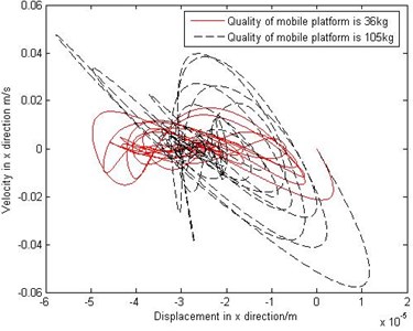
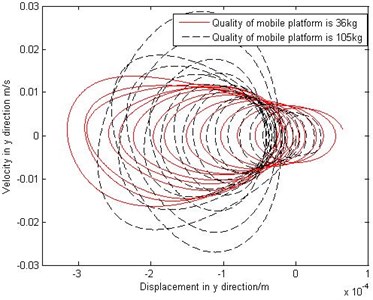
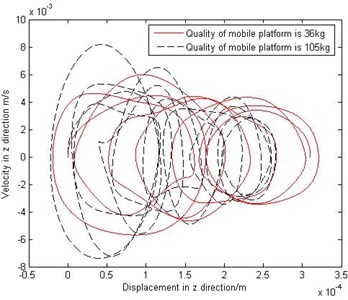
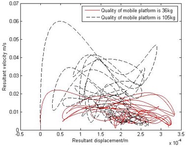
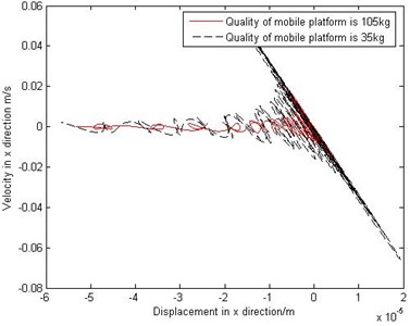
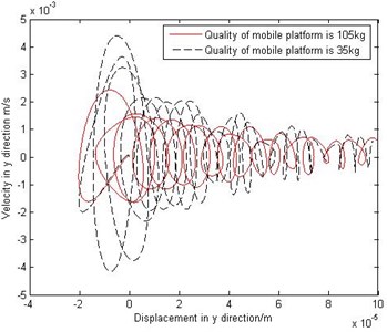
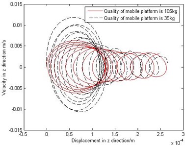
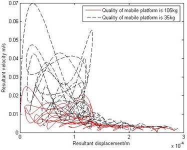
According to the given motion Eq. (21) of 4-UPS-UPU high-speed spatial parallel mechanism, when the mass of the moving platform are 36 kg and 105 kg, the phase diagram are shown in Fig. 5. From Fig. 5, the motion in the -axis direction is chaotic motion, the motion in the -axis and -axis direction are periodic motion. The motion of 4-UPS-UPU high-speed spatial parallel mechanism is chaotic motion, and the different mass of the moving platform have a very obvious effect on the phase diagram.
Fig. 3The phase diagram comparison with different material of driving limbs
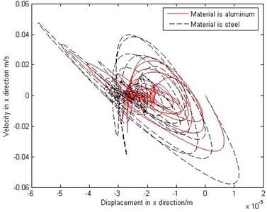
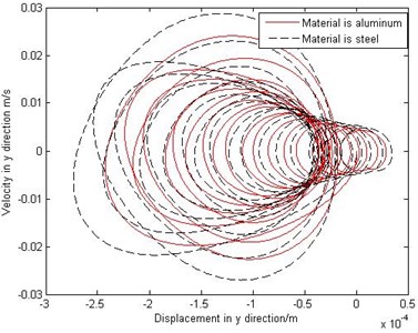
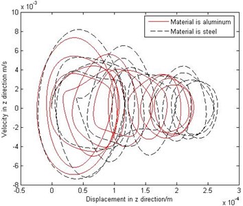
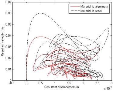
Fig. 4The phase diagram comparison with different diameter of driving limbs
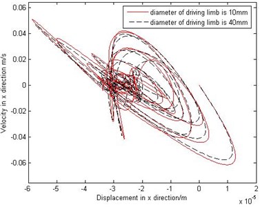
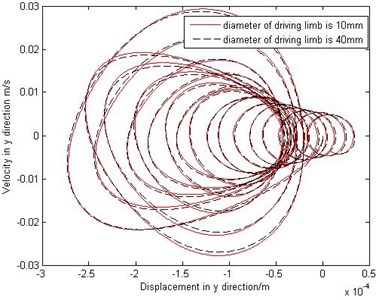
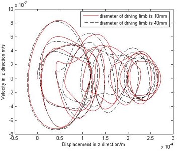
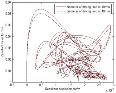
Fig. 5The phase diagram comparison with different mass of the moving platform
4.3. Numerical example 2
The law of motion for 4-UPS-UPU spatial parallel mechanism is defined as (unit: s, m):
According to the given motion Eq. (21) of 4-UPS-UPU high-speed spatial parallel mechanism, when the material of driving limbs are steel and aluminum, the phase diagram are shown in Fig. 6. From Fig. 6, the motion in the -axis direction is irregular and bounded, so its movement is in the form of chaotic motion, the motion in the -axis direction has the excessive trend from periodic motion to chaotic motion, so its movement is in the form of quasi-periodic motion, when the material of driving limbs is steel, the motion in the -axis direction is regular, when the material of driving limbs is aluminum, the motion in the -axis direction is chaotic motion. And as shown in Fig. 6, the different material of driving limbs have an obvious influence on the phase diagram.
According to the given motion Eq. (21) of 4-UPS-UPU high-speed spatial parallel mechanism, when the diameter of driving limbs are 10 mm and 40 mm, the phase diagrams are shown in Fig. 7. From Fig. 7, the different diameter of driving limbs have an obvious effect on the phase diagram.
According to the given motion Eq. (22) of 4-UPS-UPU high-speed spatial parallel mechanism, when the mass of the moving platform are 36 kg and 105 kg, the phase diagram are shown in Fig. 8. From Fig. 8, the motion in the -axis direction is chaotic motion, the motion in the -axis direction is quasi-periodic motion, when the mass of the moving platform is 105 kg, the motion in the -axis direction is regular, when the mass of the moving platform is 36 kg, the motion in the -axis direction is chaotic motion.
Fig. 6The phase diagram comparison with different material of driving limbs
4.4. Numerical example 3
The law of motion for 4-UPS-UPU spatial parallel mechanism is defined as (unit: s, m):
According to the given motion Eq. (23) of 4-UPS-UPU high-speed spatial parallel mechanism, when the material of driving limbs are steel and aluminum, the phase diagrams are shown in Fig. 9. From Fig. 9, the motion in the -axis direction is irregular and bounded, so its movement is in the form of chaotic motion, the motion in the -axis direction is regular and cyclical, but it has diffusion in the local scope, so its movement is in the form of quasi-periodic motion, the motion in the -axis direction is also in the form of quasi-periodic motion. By and large, the trajectory of 4-UPS-UPU high-speed spatial parallel mechanism, which is very complex and has a long-term unpredictability, is a typical chaotic motion. And as shown in Fig. 9, the different material of driving limbs have a certain effect on the phase diagram.
Fig. 7The phase diagram comparison with different diameter of driving limbs
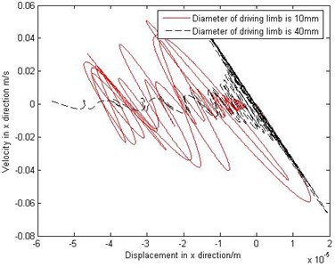
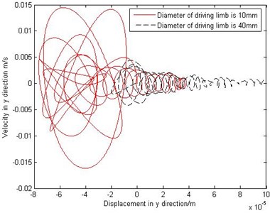
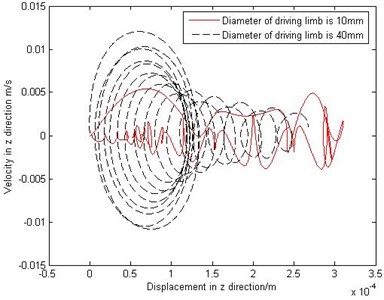
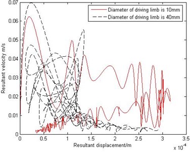
Fig. 8The phase diagram comparison with different mass of the moving platform
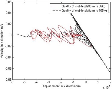
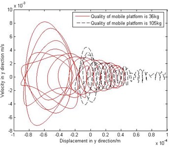
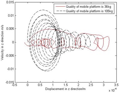
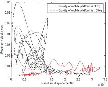
Fig. 9The phase diagram comparison with different material of driving limbs
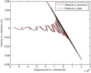
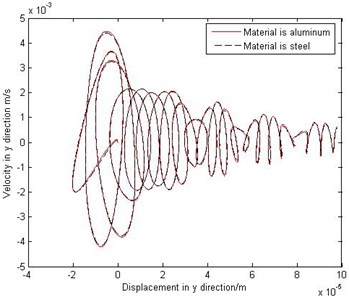
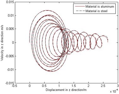
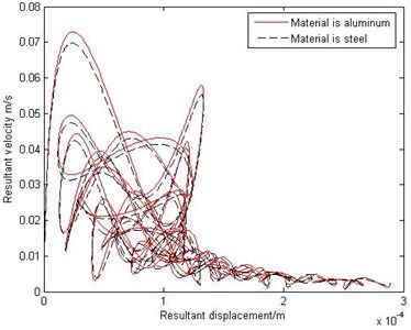
Fig. 10The phase diagram comparison with different diameter of driving limbs
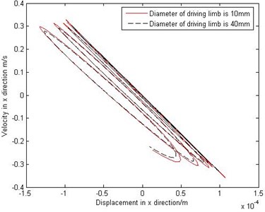
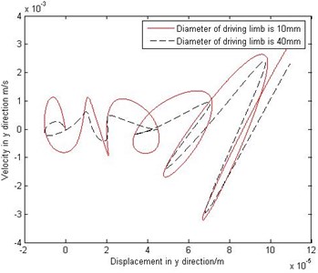
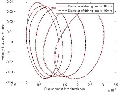
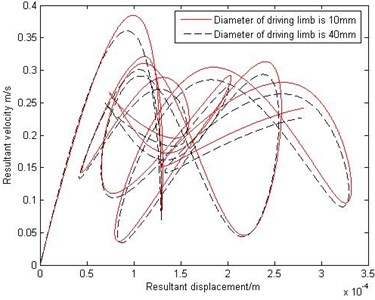
Fig. 11The phase diagram comparison with different mass of the moving platform
According to the given motion Eq. (23) of 4-UPS-UPU high-speed spatial parallel mechanism, when the diameter of driving limbs are 10 mm and 40 mm, the phase diagrams are shown in Fig. 10. From Fig. 10, the diameter of driving limbs have a certain effect on the phase diagram.
According to the given motion Eq. (23) of 4-UPS-UPU high-speed spatial parallel mechanism, when the mass of the moving platform are 36 kg and 105 kg, the phase diagram are shown in Fig. 11. From Fig. 11, the motion in the -axis direction is chaotic motion, the motion in the -axis and -axis direction are periodic motion. The motion of 4-UPS-UPU high-speed spatial parallel mechanism is chaotic motion, and the different mass of the moving platform have a very obvious effect on the phase diagram.
By comparing the phase diagrams of the given motion Eqs. (1)-(3) of 4-UPS-UPU high-speed spatial parallel mechanism, the chaotic motion occurs in the movement, the parallel mechanism shows a typical nonlinear characteristics, and the different trajectory has an obvious effect on the phase diagram of parallel mechanism.
5. Conclusions
1) The nonlinear elastic dynamic equation of 4-UPS-UPU spatial parallel mechanism is established.
2) The dynamic equation is solved by Newmark method, the nonlinear characteristics of the parallel mechanism is analyzed by phase diagram.
3) 4-UPS-UPU high-speed parallel mechanism shows chaotic motion in the movement. The trajectory of the mechanism, the material of driving limb, the diameter of driving limb and the mass of the moving platform have a certain impact on the nonlinear characteristics of mechanism, respectively.
References
-
Santosha K. D., Peter E. Dynamic analysis of flexible manipulators, a literature review. Mechanism and Machine Theory, Vol. 41, 2006, p. 749-777.
-
Haihong I., Yang Zhiyong, Huang Tian Dynamics and elasto-dynamics optimization of a 2-DOF planar parallel pick-and-place robot with flexible links. Structural and Multidisciplinary Optimization, Vol. 38, Issue 2, 2009, p. 195-204.
-
Zhang X. P., Mills J. K., Cleghorn W. L. Dynamic modeling and experimental validation of a 3-PRR parallel manipulator with flexible intermediate links. Journal of Intelligent and Robotic Systems, Vol. 50, 2007, p. 323-340.
-
Zhang Minghui, Huang Tian Research on elastic dynamic analysis and test for Diamond mechanism. Journal of Machine Design, Vol. 21, Issue 11, 2004, p. 6-8, (in Chinese).
-
Zhao Yongjie, Gao Feng, Dong Xingjian, et al. Elastodynamic characteristics comparison of the 8-PSS redundant parallel manipulator and its non-redundant counterpart – the 6-PSS parallel manipulator. Mechanism and Machine Theory, Vol. 45, Issue 2, 2010, p. 291-303.
-
Yao Jianxin, Chen Yong Kineto-elastodynamic analysis of parallel industrial robotic manipulators. Robot, Vol. 18, Issue 6, 1996, p. 328-331, (in Chinese).
-
Nidal Farhat, Vicente Mata, Álvaro Page, et al. Identification of dynamic parameters of a 3-DOF RPS parallel manipulator. Mechanism and Machine Theory, Vol. 43, Issue 4, 2008, p. 1-17.
-
Liu Shanzeng, Yu Yueqing, Su Liying, et al. Dynamics modeling and frequency analysis of a 3-RRS flexible parallel manipulator. China Mechanical Engineering, Vol. 19, Issue 10, 2008, p. 1219-1223.
-
Chen Xiulong, Wei Deyong, et al. Nonlinear elastodynamic behaviour analysis of high-speed spatial parallel coordinate measuring machines. International Journal of Advanced Robotic Systems, Vol. 9, Issue 140, 2012, p. 1-6.
-
Shiau T. N., Tsai Y. J., Tsai M.-S. Nonlinear dynamic analysis of a parallel mechanism with consideration of joint effects. Mechanism and Machine Theory, Vol. 43, Issue 4, 2008, p. 491-505.
-
Li Yangmin, Xu Qingsong Modeling and performance evaluation of a flexure-based XY parallel micromanipulator. Mechanism and Machine Theory, Vol. 44, Issue 12, 2009, p. 2127-2152.
About this article

This research is supported by the National Natural Science Foundation of China (Grant Nos. 51005138, 11272190, 11272167), Shandong Young Scientists Award Fund (Grant No. BS2012ZZ008), Taishan Scholarship Project of Shandong Province (No. tshw20130956), the Science Foundation of SUST (Grant No. 2011KYJQ102), the Project of Jiangsu Key Laboratory of Digital Manufacturing Technology (Grant No. HGDML-1104).
