Abstract
This paper focuses a new 4-UPS-RPS five degree of freedom (DOF) spatial parallel robot mechanism with independent intellectual property rights obtained. Based on KED method and together with finite element method, Lagrange equation and substructure modeling method, the elastokinetics analytical model of this parallel robot mechanism is established under the ideal situation. Subsequently, the research results, such as elastokinetics model, stress and frequency characteristic analysis, are obtained. Combined with typical examples, key design parameters which significantly influence the dynamic characteristics of the system, are explicated. The work done in this paper lays a solid foundation for the dynamic optimum design of parallel robot mechanism and the physical prototype development.
1. Introduction
With a variety of advantages, such as high stiffness-mass ratio, no error accumulation and large bearing capacity, the parallel robot mechanism is regarded as a complementation of serial mechanism in practical application, and of course, parallel robot mechanism study is becoming a research focus in the area of international robot research and application [1, 2]. With external load and periodic inertial force, components of the mechanism will develop a certain degree of elastic deformation, causing kinematic error and components elastic vibration, which greatly degrade the mechanism’s kinematic and dynamic performance and reduce working accuracy. Therefore, elasticity factor must be considered for parallel robot mechanism which has high accuracy and high performance requirement [3].
Some scholars have made a series of efforts on the elastokinetics modeling method and dynamic characteristics analysis. According to elastokinetics modeling, by taking the elastic deformation into account, Xuping Zhang [4], Qingsong Xu [5] Lee [6] and Kang [7, 8] derive the dynamic equation of flexible parallel mechanism via Lagrangian approach; Xiaoyun Wang [9] and Zhao [10] introduce substructure modeling method and finite element method to establish the dynamic model parallel mechanism; Yundou Xu [11] derives compatibility equation of the elastic deformation based on the law of conservation of energy; Shaochi Wang [12] uses virtual work principle; Piras [13] and Liu [14] accepte KED method; Chen [15] introduces multi flexible body dynamics method to build elastokinetics model. Dynamic characteristics analysis is also explored by researches. After establishing dynamic equations of the spatial rigid-flexible coupling multibody systems for a five-coordinate virtual-axis hybrid polishing machine tool, Lu Y. [16] studies its dynamic characteristics by means of the theory of dynamics of a flexible multibody system and builds the finite element models of the whole machine tool and each leg respectively; Piras [14] studies the natural frequency distribution discipline of 3-PRR parallel mechanism and analyzes its domain of convergence; Zhao [10] dose the system dynamic characteristics analysis, like natural frequency, sensitivity analysis and other dynamic properties analysis; Chen [15] acquires displacement error, velocity error and acceleration error of the moving platform; Liu [14] analyzes the relationship between system natural frequency and basic parameters. Besides, some basic studies, like static analysis and dynamic analysis [17-20], are also quite useful. Although scholars have done a lot of works, the research of elastokinetics modeling and analysis for parallel mechanism are still quite immature as the modeling and solving process is still quite complicated. Therefore, elastokinetics analysis of flexible parallel mechanism by mathematical modelling of parallel mechanism is a valuable direction.
Learning from other researches’s experiences and avoiding their weakness, we select some several methods that are suitable for our new 4-UPS-RPS spatial parallel robot mechanism, and explore some dynamic characteristics, such as kinematic error, stress and frequency characteristic analysis. It is necessary to establish the elastokinetics model and give characteristic analysis, as dynamic stress analysis is the foundation of studying mechanism’s failure modes and the fatigue life, and it plays a significant role on mechanism’s structure design and control strategy design.
2. Elastokinetics modeling and solving
2.1. The model of 5-DOF spatial parallel robot mechanism
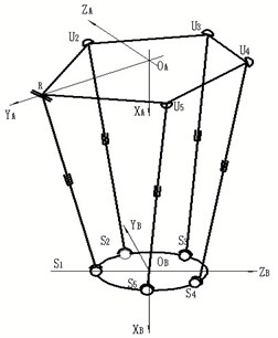
The 4-UPS-RPS 5-DOF spatial parallel robot mechanism(see Fig. 1) is consists of a fixed platform, a moving platform, a RPS(revolute pair – sliding pair – spherical hinge) driving limb and four UPS (Hooke joint – sliding pair – spherical hinge) driving limbs. Each driving limb is divided into two parts, an oscillating rod and an expansion link. Analyzed by Screw theory [18], this mechanism has five degrees of freedom, and the moving platform can achieve three-dimensional translation and two-dimensional rotation by changing length of each driving limb.
Fig. 1Mechanism diagram of parallel robot mechanism
2.2. The elastokinetics equation for unit
The (when , means RPS) is defined as five driving limbs of 4-UPS-RPS parallel robot mechanism, each driving limb consists of a oscillating rod and an expansion link and sliding pairs connect oscillating rods with expansion links respectively. Assume that all expansion links are flexible, all the oscillating rods and the moving platform are rigid, and flexibility of each joints are ignored. Take a random unit as the research object, use rectangular space beam element as the finite element model, and build the unit local coordinate system . Subscript expresses the unit on driving limb . Two endpoints on unit are written as and respectively. symbolizes generalized coordinates vector of unit , and , and repersent elastic displacement, elastic angle and curvature of endpoints respectively; , , repersent elastic displacement, elastic angle and curvature of endpoints respectively.
According to KED method, when the mechanism works, unit coupling effect between rigid motion and elastic deformation motion can be ignored due to units’ tiny elastic deformation displacement. In other words, absolute velocity at any point on the unit is the superposition of elastic deformation velocity and rigid motion velocity, and so does the absolute acceleration computing method. As the result, velocity of random point in unit coordinate system can be expressed as:
where , , and mean elastic velocity and elastic angular velocity of random point . , , and mean rigid body velocity and rigid body angular velocity of random point ; , , and mean absolute velocity and absolute angular velocity of random point .
2.2.1. The kinetic energy for unit
Assuming that each unit’s cross-section mass is concentrated on the axis, the kinetic energy of unit can be expressed as the superposition of unit translational energy and unit rotational kinetic energy:
where is the unit length; is unit mass density; is unit cross sectional area; is polar moment of inertia of unit cross section to theaxis; is unit mass distribution function, for homogeneous beam unit .
After simplification, the equation can be written as:
where is element mass matrix.
2.2.2. The deformation energy for unit
The deformation energy of unit can be expressed as the superposition of unit bending, stretching, compression and torsional deformation energy:
where is the material’s stretching and compression elasticity modulus; is the material’s shearing elasticity modulus; is principal moment of inertia of unit cross section to the axis; is principal moment of inertia of unit cross section to the axis.
After simplification, the equation can be written as:
where is element stiffness matrix.
2.2.3. The unit elastokinetics equation
Taking Eq. (3) and Eq. (5) into Lagrange equation:
the unit elastokinetics equation can be acquired:
For the mechanism in this paper, is the generalized external force array of each unit; is the force array which is caused by other units which connect with the objective unit working on this objective unit, and belongs to internal force of the mechanism, which can be cancelled out when unit elastokinetics equations are assembled to the system elastokinetics equation; is the rigid body inertia force array of unit, .
2.3. Elastokinetics equation for driving limb
2.3.1. The constraints analysis between units
Constraint conditions: units wrapped in rigid body have no elastic displacement, elastic angular displacement or curvature; in other words, those units’ elastic displacement, elastic angular displacement and curvature coordinates are zero; endpoint of unit on driving limb coincides with of unit on driving limb ; on driving limb , the last unit connects the moving platform by spherical hinge, so three curvatures coordinates of unit are zero (The number of units that each expansion link is divided into is , and the last unit on the expansion link which endpoint is joint names ).
By synthesizing elastic displacement, elastic angular displacement and curvature of unit nodes on driving limb , independent generalized coordinates can be gotten:
Relasionship between driving limb generalized coordinates and unit generalized coordinates can be expressed as:
where is the transfer matrix form driving limb to unit.
2.3.2. Elastokinetics equation for driving limb
Elastokinetics equation for driving limb can be written as:
where is the mass matrix of the expansion link, and ; is the damping matrix of the expansion link and ; is the stiffness matrix of the expansion link and is the generalized force matrix of the expansion link, and .
2.4. Elastokinetics equation for system
2.4.1. The kinematical constraint
The kinematical constraint of the parallel robot mechanism is expressed as:
where is the displacement of spherical hinge; ; is displacement of moving platform caused by the elastic deformation of the expansion link; . , and express the coordinate of spherical point on the fixed platform.
2.4.2. The dynamic constraint
Force caused by every driving limbs working on the moving platform should be equal with external force acted on the moving platform.
According to Newton-Euler equation, the dynamic equation can be written as:
where is generalized mass matrix of the moving platform; is resultant force and moment array of driving limbs working on the moving platform; is resultant force and moment array of external force working on the moving platform; is moving platform nominal acceleration array.
2.4.3. The elastokinetics equation for system
The system generalized coordinate can be written as:
where is the transfer matrix form system to driving limbs. is the generalized coordinate on driving limbs, is the system generalized coordinate.
The influence of damping should be considered when modeling. Assuming the system damping is proportional damping, considering kinematical and dynamic constraints, and using transfer matrix, the system elastokinetics equation can be acquired by assembling driving limb elastokinetics equations. The system elastokinetics equation can be expressed as:
where is the system total damping matrix; is the system total mass matrix; is the system total stiffness matrix; is the system total generalized force matrix.
By far, linear system elastokinetics equations based on the high speed spatial parallel robot mechanism have been established. Eqs. (10), (11) and (13) are the linear system elastokinetics model.
2.5. Equation solving
As equation is a coupled variable coefficient differential equation, it is difficult to solve. Under a certain conditions, Newmark method is a unconditionally stable numerical integral method, and its accuracy requirement can be acquired by changing the time step. Due to the overall consideration of accuracy, stability and computation speed of equation solving, Newmark method is introduced to solve system elastokinetics equations in this paper.
3. Dynamic analysis of flexible parallel robot mechanism
3.1. The dynamic stress analysis of flexible parallel robot mechanism
Dynamic stress analysis of flexible parallel robot mechanism is one of the main research targets in this paper. If component’s maximum dynamic stress exceeds allowable stress, the component will be damaged. Dynamic stress analysis is the basis of studying mechanism’s failure modes and the fatigue life, and it plays a significant role on mechanism design and the control strategy enacting.
At any time, absolute value of the maximum dynamic stress and maximum shearing stress on unit’s cross section area can be written as:
where:
The equivalent stress which is defined by the fourth strength theory, is one of the most representative indicators in finite element analysis, and the equivalent stress can be expressed as:
where , and are three principal stresses of random point on component.
3.2. The natural frequency analysis of flexible parallel robot mechanism
The system natural frequency is determined by mechanism’s internal parameters, and it is closely related to the stiffness and singular configuration of the structure. System inherent frequency study characterize the vibration of the system as a whole.
Solving the natural frequency comes down to solve generalized eigenvalue of stiffness matrix related to the mass matrix. According to the system elastokinetics equation, the system characteristic equation can be written as:
wehere is the system natural frequency, is the order natural mode of vibration (1, 2..., ).
According to Eq. (16), system natural frequency is determined by the system total mass matrix and the sytem total stiffness matrix . Three basic parameters (geometry structure of component, size of cross section, and material property) determine the frequency characteristic of the parallel robot mechanism system essentially. Therefore, it is quite difficult to do the theoretical analysis of parallel robot mechanism’s system natural frequency. At the moment, frequency characteristic can only be discussed indirectly by numerical example or software simulation.
4. The numerical simulation analysis
4.1. Structure parameters of the 4-UPS-RPS spatial parallel robot mechanism
The structure parameters of 4-UPS-RPS spatial parallel robot mechanism is shown in Table 1 and Table 2.
Table 1Parameters of the moving platform
Material | Density, g/cm3 | Mass, kg | Stretching and compression elasticity modulus, GPa | Shear elasticity modulus, GPa | Poisson ratio |
Aluminum | 2.70 | 36.28 | 72 | 26 | 0.32 |
Table 2Parameters of the driving limbs
Material | Density, g/cm3 | Stretching and compression elasticity modulus, GPa | Shear elasticity modulus, GPa | Poisson ratio |
Steel | 7.85 | 206 | 79 | 0.28 |
Length of oscillating rod mm | Length of expansion link mm | Cross sectional area of expansion link mm2 | ||
670 | 841 | 12.56637 | ||
4.2. Dynamic analysis results of the spatial parallel robot mechanism
The moving platform of 4-UPS-RPS spatial parallel robot mechanism is to do circular motion with the pose of , , . And the -coordinate of the center for the circle is 0.920, the -coordinate of the center for the circle is –0.15, the -coordinate of the center for the circle is 0. The establishment of coordinate systems is shown in Fig. 1. Therefore, the motion of 4-UPS-RPS spatial parallel robot mechanism is described as follows:
where is the -coordinate of the center of moving platform, is the -coordinate of the center of moving platform, is the -coordinate of the center of moving platform.
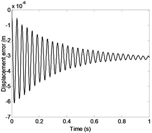
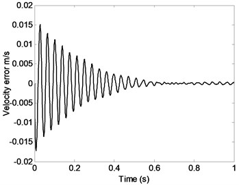
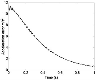
Fig. 2 shows that displacement error, velocity error or acceleration error of the moving platform change over time. It is clear that obvious vibration of the moving platform is caused by the elastic deformation of system components, which leaves a great negative impact on the precision of the parallel robot mechanism. The system stiffness is not the same when the parallel robot mechanism system is under different pose and position, therefore, displacement, velocity and acceleration of each point on the system are closely related to the parallel robot mechanism’s pose and position. Therefore, choosing appropriate initial configuration of the system is good for the high precision control of parallel robot mechanism and the improvement of motion and dynamic characteristics.
Fig. 2Displacement error, velocity error or acceleration error of the moving platform changing with time
a)
b)
c)
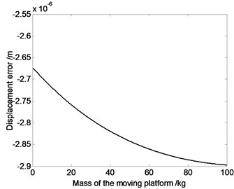
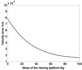
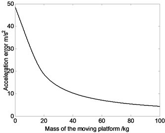
Fig. 3The relation curve of displacement error, velocity error or acceleration error of the moving platform and the mass of the moving platform
a)
b)
c)
Fig. 3 shows that absolute value of displacement error sees a upward trend as the mass of the moving platform increases, while average value of velocity and acceleration error see a downward trend. That is because when mass of moving platform increases, the system inertia force increases, which lead to the raising of displacement error. Meanwhile, when the mechanism moves, heavy mass of moving platform and large rotational inertia can absorb or release more elastic vibration energy, which inhibits the motion fluctuations and causes the decrease of velocity and acceleration error.
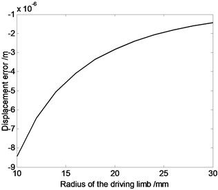
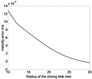
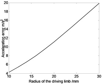
Fig. 4The relation curve of displacement error, velocity error or acceleration error of the moving platform and the radius of the driving limb
a)
b)
c)
As shown in Fig. 4, absolute value of displacement error and velocity error see a downward trend, while average value of acceleration error see a upward trend as the radius of the driving limb increases. The influence of moving platform and expansion link’s inertia parameters on dynamic response of flexible parallel robot mechanism is significantly different to that on flexible serial mechanism. The primary reason is that, parallel robot mechanism belongs to multi-loop system, so the influence of moving platform and expansion link’s inertia parameters on disparate branches’ kinematic movement is different. However, movement coupling relationship exists among components, and coupling relationship may lead to the cancellation of some elastic deformation. As a result, movement error of the system may not always decrease with the increase of radius of the driving limb.
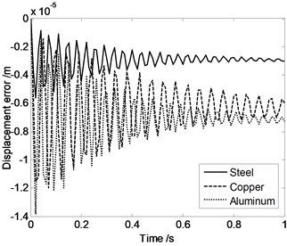
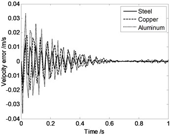
It is clear that in Fig. 5, maximum displacement error appears when the moving platform and expansion links are made by aluminum. And minimum displacement error appears when the driving limbs are made by steel. Maximum acceleration error appears when the driving limbs are made by aluminum and minimum acceleration error appears when the driving limbs are made by copper. These conclusions provide a basis for the parallel robot mechanism’s materials selection.
Fig. 5Displacement error, velocity error or acceleration error of the moving platform changing with time when the moving platform and expansion links are made by different materials
a)
b)
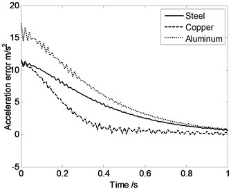
c)
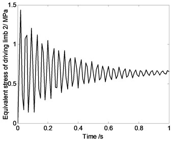
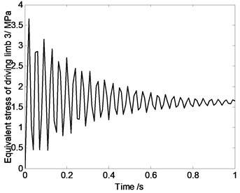
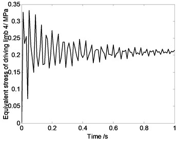
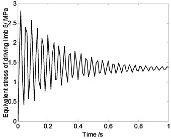
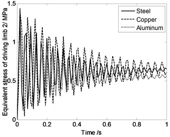
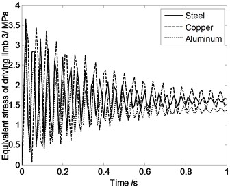
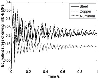
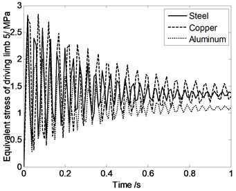
Fig. 6Equivalent stress of driving limbs changing with time
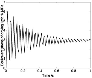
a)
b)
c)
d)
e)
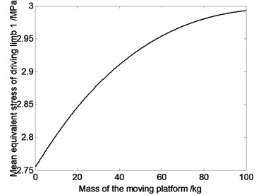
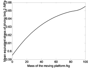
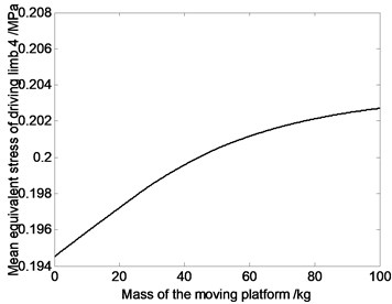
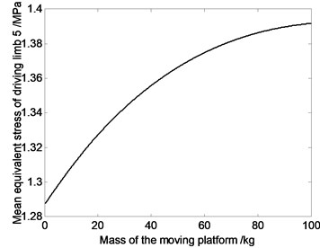
Fig. 7The relation curve of equivalent stress of driving limbs and mass of moving platform
a)
b)

c)
d)
e)
As shown in Fig. 6, the driving limb’s maximum equivalent stress oscillates when parallel robot mechanism’s position changes. That is because, components’ elastic deformation is closely related to the system reciprocating vibration movement characteristics. In the process of movement, stress characteristics of high speed spatial parallel robot mechanism is very complex. When doing the mechanism design and motion planning, it is necessary to do the dynamic analysis. For this 4-UPS-RPS spatial parallel robot mechanism, when motion is described as Eq. (17), maximum equivalent stress appears on driving limb 1, and its maximum value is 6 MPa.
Fig. 7 shows that average value of equivalent stress on driving limb decreases with the decrease of the mass of moving platform. So dynamic response of the mechanism can be improved by choosing reasonable mass of the moving platform. That is because, if the components’ mass get smaller, the inertia force would get smaller. Under the same kinematics condition, dynamic characteristic of lighter mechanism is better. Meanwhile, the smaller the joints’ counter-forces are, the smaller the joints’ driving devices will be, and that will cause the miniaturization of the joints’ driving devices.
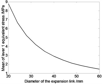
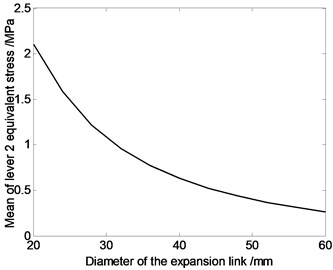
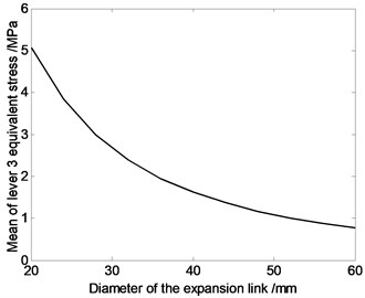
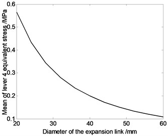
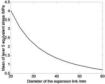
Fig. 8The relation curve of equivalent stress of driving limbs and diameter of the driving limb
a)
b)
c)
d)
e)
According to Fig. 8, average value of equivalent stress on driving limb 1 is larger, and each driving limb’s average equivalent stress decreases with the increase of the driving limb’s sectional area. That is because the greater the driving limb’s cross-sectional area is, the greater the driving limb’s strength will be, and mechanical properties will improve.
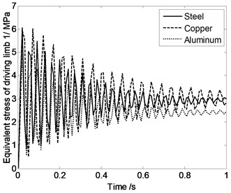
According to Fig. 9, Equivalent stress of driving limbs are similar when the moving platform and expansion links are made by different materials. That means material property has very little influence on the equivalent stress of driving limbs.
Fig. 9Equivalent stress of driving limbs changing with time when the moving platform and expansion links are made by different materials
a)
b)
c)
d)
e)
Fig. 10 shows that the numerical value of system natural frequency changes related to the different pose and position of mechanism. This conclusion is different from the serial mechanism. Main reason is that, the coupled parallel robot mechanism system is closed-loop organization system, and many factors, such as kinematic and dynamic constraints among limbs and mass of moving platform, seriously affect the dynamic characteristics of the system. Therefore, relations between the system’s first order natural frequency of rigid-flexible coupling parallel robot mechanism and the components material parameters are pretty complex.
Fig. 10The first three natural frequency changing with time
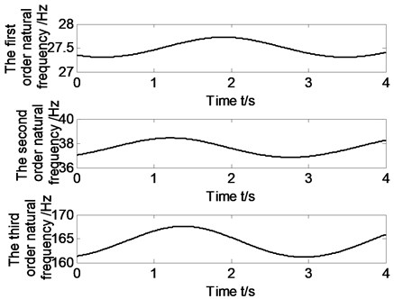
Fig. 11The relation curve of the first order natural natural frequency and mass of moving platform
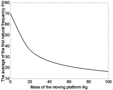
It is clear that in Fig. 11, with increasing of the mass of moving platform, the first order natural frequency of system sees a downward trend. Therefore, when doing system structure design of rigid-flexible coupling parallel robot mechanism, we can achieve the goal of improving system dynamic characteristics by choosing reasonable mass of the moving platform.
Fig. 12Natural frequency changing with time when the moving platform and expansion links are made by different materials
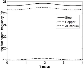
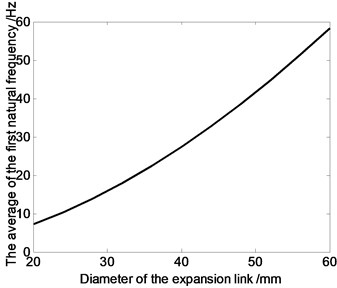
Fig. 13The relation curve of the first order natural frequency and expansion links’ diameter
According to Fig. 12, system natural frequency differect with components made by different materials, such as steel, aluminum and copper. Maximum natural frequency appears when the moving platform and expansion links are made by steel and minimum natural frequency appears when the driving limbs are made by Copper. These conclusions provide a basis for the parallel robot mechanism’s materials selection.
Fig. 13 shows that the numerical value of the first order natural frequency of system changes related to the differect flexible expansion links’ radius. With increasing of the expansion links’ radius, the first order natural frequency of system sees a upward trend. Therefore, when doing system structure design of rigid-flexible coupling parallel robot mechanism, we can achieve the goal of improving system dynamic characteristics by choosing reasonable diameter of the flexible expansion links.
5. Conclusions
Taking the 4-UPS-RPS high speed spatial parallel robot mechanism as the research object, elastokinetics model is established, and dynamic behavior is analysed. The main conclusions are as follows
1) Based on KED method, using finite element method, Lagrange equation and substructure modeling method, the analytical model of elastic dynamics of the parallel robot mechanism is successfully established under the ideal situation.
2) According to the fourth strength theory, equivalent stress of the driving limbs is studied. Natural frequency of the parallel robot mechanism is analyzed. These works laid the important theoretical basis for further dynamics behavior study and optimization design of the high-speed spatial parallel robot mechanism.
3) By giving a trajectory, using Matlab simulation software, dynamics behavior such as displacement error, velocity error and acceleration error, driving limbs’ equivalent stress and system natural frequency, are acquired.
References
-
Piccin O., Bayle B., Maurin B., de Mathelin M. Kinematic modeling of a 5-DOF parallel mechanism for semi-spherical workspace. Mechanism and Machine Theory, Vol. 44, Issue 8, 2009, p. 1485-1496.
-
Chen Xiulong, Sun Xianyang Dexterity analysis of 4-UPS-RPS parallel mechanism. International Journal of Advanced Robotic Systems, Vol. 9, 2012, p. 1-8.
-
Chen Xiulong, Jia Shuaishuai, Deng Yu, Zhao Yongsheng Dynamic behaviors of rigid flexible coupling for novel 4-UPS-UPU parallel coordinate measuring machine. Journal of Jilin University (Engineering and Technology Edition), Vol. 41, Issue 4, 2011, p. 1020-1024, (in Chinese).
-
Zhang Xuping, Mills James K., Cleghorn William L. Coupling characteristics of rigid body motion and elastic deformation of a 3-PRR parallel manipulator with flexible links. Multibody System Dynamics, Vol. 21, Issue 2, 2009, p. 167-192.
-
Xu Qingsong, Li Yangmin Statics and dynamics performance evaluation for a high precision XYZ compliant parallel micromanipulator. 2007 IEEE International Conference on Robotics and Biomimetics, 2008, p. 65-70.
-
Lee J. D., Geng Z. A dynamic model of a flexible Stewart platform. Computer and Structures, Vol. 48, Issue 3, 1993, p. 367-374.
-
Kang B., Mills J. K. Dynamic modeling of structurally flexible planar parallel manipulator. Robotica, Vol. 20, Issue 3, 2002, p. 329-339.
-
Kang B., Yeung B., Mills J. K. Two-time scale controller design for a high speed planar parallel manipulator with structural flexibility. Robotica, Vol. 20, Issue 5, 2002, p. 519-528.
-
Wang Xiaoyun, Mills James K. Dynamic modeling of a flexible-link planar parallel platform using a substructuring approach. Mechanism and Machine Theory, Vol. 41, Issue 6, 2006, p. 671-687.
-
Zhao Yongjie, Gao Feng, Dong Xingjian, Zhao Xianchao Dynamics analysis and characteristics of the 8-PSS flexible redundant parallel manipulator. Robotics and Computer-Integrated Manufacturing, Vol. 27, Issue 5, 2011, p. 918-928.
-
Xu Yundou, Yao Jiantao, Zhao Yongsheng Inverse dynamics and internal forces of the redundantly actuated parallel manipulators. Mechanism and Machine Theory, Vol. 51, 2012, p. 172-184.
-
Wang Shaochi, Hikita Hiromitsu, Kubo Hiroshi, Zhao Yongsheng, Huang Zhen, Ifukube Tohru Kinematics and dynamics of a 6 degree-of-freedom fully parallel manipulator with elastic joints. Mechanism and Machine Theory, Vol. 38, Issue 5, 2003, p. 439-461.
-
Piras G., Cleghorn W. L., Mills J. K. Dynamic finite-element analysis of a planar high-speed, high-precision parallel manipulator with flexible links. Mechanism and Machine Theory, Vol. 40, Issue 7, 2005, p. 849-862.
-
Liu Shanzeng, Yu Yueqing, Sun Li ying, Yang Jianxin Dynamics modeling and frequency analysis of a 3-RRS flexible parallel manipulator. China Mechanical Engineering, Vol. 19, Issue 10, 2008, p. 1219-1223.
-
Chen Xiulong, Wei Deyong, Li Wenbin, Deng Yu Nonlinear elastodynamic behaviour analysis of high-speed spatial parallel coordinate measuring machines. International Journal of Advanced Robotic Systems, Vol. 9, 2012, p. 918-928.
-
Lu Y., Zhao J., Zhang L., Wang Y. Study on the dynamic characteristics of a virtual-axis hybrid polishing machine tool by flexible multibody dynamics. Proceedings of the Institution of Mechanical Engineers, Vol. 218, Issue 9, 2004, p. 1067-1076.
-
Liu Dejun, Huang Qingcheng, Che Rensheng, Ai Qinghui A measuring model study of a new coordinate measuring machine based on the parallel kinematic mechanism. Measurement Science and Technology, Vol. 10, Issue 11, 1999, p. 1020-1024.
-
Khan Waseem Ahmad, Krovi Venkat N., Saha Subir Kumar, Angeles Jorge Modular and recursive kinematics and dynamics for parallel manipulators. Multibody System Dynamics, Vol. 14, Issues 3-4, 2005, p. 419-445.
-
Chen Xiulong, Feng Weiming, Sun Xianyang, Gao Qing Kinematics analysis of a parallel coordinate measuring machine. International Journal of Advanced Robotic Systems, Vol. 10, 2013, p. 1-6.
-
Wu Peidong, Xiong Hegen, Kong Jianyi Dynamic analysis of 6-SPS parallel mechanism. International Journal of Mechanics and Materials in Design, Vol. 8, Issue 2, 2012, p. 121-128.
About this article

This research is supported by the National Natural Science Foundation of China (Grant Nos. 51005138, 11272190, 11272167), Shandong Young Scientists Award Fund (Grant No. BS2012ZZ008), Program for Changjiang Scholars and Innovative Research Team in University (IRT1266), Taishan Scholarship Project of Shandong Province (No. tshw20130956), Supported by Program for Scientific Research Innovation Team in Colleges and Universities of Shandong Province, Special funds for Cultivation of Taishan Scholars, the Science Foundation of SUST (Grant No. 2011KYJQ102), the project of Jiangsu key Laboratory of Digital Manufacturing Technology (Grant No. HGDML-1104).
