Abstract
Variable guide vanes turbines are widely applied in turbocharger. To assess the effects of pulsation inlet conditions on the aerodynamic excitation and the forced vibration of turbine wheel, the weak fluid structure interaction method was adopted. Firstly, a pulsation flow with the frequency of 60 Hz (which corresponds to the engine speed of 2400 r/min) was applied at the turbine inlet to conduct the unsteady flow calculation. The results show that the aerodynamic loads are highly influenced by the pulsation inlet conditions, which fluctuate with the inlet pulsation wave in a pulse cycle, and the maximum and minimum blade load corresponding to the peak and trough of the inlet pulsation wave respectively. For the forced vibration analysis of turbine wheel, the calculated aerodynamic loads in pulsation flow were imposed as the loading boundaries to perform the harmonic vibration and transient structural response by FE calculations, based on the natural frequency and mode of the blade disk. The results show that the forced response of the blade disk not only reflects the contribution of low frequency pulsation excitations but also contains the high frequency pressure fluctuations caused by rotor rotation.
1. Introduction
Nowadays, most vehicle engines are turbocharged to meet the ever-increasing demands of stricter exhaust emission, higher engine power and fuel economy. Compared with the heavy turbomachines applied to the power plants, the exhaust gas turbochargers used in the automobiles are much smaller and work at higher rotor speeds in various operating conditions. The rotor speeds of turbine and compressor wheels are up to 120,000 rpm and the maximum circumferential velocity of turbine is approximately 560 m/s [1]. The aerodynamic and inertial forces acting on the rotor blades will cause excessive rotor forced vibration and lead to structural high cycle fatigue (HCF) [2, 3]. Therefore, the forced response of the turbocharger turbine caused by the aerodynamic excitations should be paid special attentions.
In exhaust gas turbocharger system, besides the inherent unsteady flow of turbomachinery, the non-uniform flow phenomenon is inevitable existed in the turbine internal because of the unsteady inlet condition. Turbocharger is directly mounted at the downstream exhaust manifold of the engine, which means the inlet of turbine is pulsation flow due to the reciprocate motion of internal combustion engine (ICE). Compared with the steady inlet conditions, the pulsation flow through the turbine stage certainly enhances the unsteadiness of the flow, induces blade pressure fluctuation and affects the aerodynamic performance of turbine. Investigations on the performance and the unsteady flow of turbocharger turbines with pulsation inlet conditions had been conducted both in experimental and numerical methods, such as, by Winterbone, et al. [4], Szymko et al. [5], Lam et al. [6], Palfreyman and Martinez-Botas [7], Padzillah et al. [8]. The researches most paid attentions to the effects of pulsation inlet conditions on the turbine’s aerodynamic performance and the unsteady flow phenomenon, but few of them considered the effects of pulsation flows on the blade pressure fluctuation and the forced response of turbine rotor. Hans et al. [9] presented an analysis of the aerodynamic excitation and blade vibration in a radial inflow turbine. Liu et al. [10] investigated the forced response of the radial turbine in the frequency domain by numerical method. Both of them paid attentions to the aerodynamic excitations resulting from the interference with guide vanes, but neglected the pulsation inlet conditions in the unsteady calculations. Filsinger et al. [11] studied the vibration characteristics of a radial turbine wheel for automotive turbocharger application. But the pulsating nature of inlet flow conditions was also not considered in CFD modeling.
Additionally, for the blade disk of turbine, mistuning inevitably exits due to small differences in geometry and material among the blades, which causes the number of possible resonances increase significantly and leads to mode localization and induces significant dynamic stress [12-14]. Researches on mistuning identifications have been performed mainly in the aero engine fields. Recently, mistuning investigations are gradually conducted in automotive turbocharger. Hemberger et al. [15-17] pointed out that the mistuning of turbine or compressor leads to an amplification of blade vibration amplitudes and hence to increases the stresses of blades by theoretical and experimental investigations. And the numerical models of the mistuning effects of turbine wheels for automotive turbocharger applications were created and validated. Hattori [18] investigated the mistuned vibration for the turbine blade disk of automotive turbocharger considering the frequency and geometric mistuning.
In this work, the non-uniform pulsation flow through the turbine was investigated and the pressure perturbation caused by the pulsation flow was obtained. The application of numerical method based on weak fluid and structure interaction (FSI) was adopted to evaluate the blade vibration and forced response of the turbine wheel with the effect of mistuning issue considered.
2. Theory analysis
The partially coupling method was used to solve the coupled fluid and structure problems for turbocharger turbine. The sequential coupling method introduced by Filsinger et al. [19, 20] was adopted, which based on the assumption of the sufficient small blade deformation so that aerodynamic excitation can be calculated by assuming to a non-vibrating structure.
For the unsteady flow calculation, the Reynolds-Averaged Navier-Stokes (RANS) equations are expressed by the form of integral as follow:
where, is the volume and is the surface; is the vector of the conservative variable; and are respectively the inviscid and viscous flux vectors; contains the source terms.
By numerical solving the RANS equations, the time-resolved pressures on the blade surfaces are obtained, which can be divided into two parts, including the time average term and the fluctuation term, given by:
For the pressure fluctuation term, it is time-variation. The Fourier transformation (FFT) is performed to convert the pressure fluctuation from the time domain to frequency domain.
The general structural dynamic equations are written as follow:
where, and are the stiffness and mass matrix; and are mechanical and aerodynamic damping matrix; is the displacement, and is the force. Deviations of the mass and stiffness respectively represent the mass and frequency mistuning.
To model the mistuned systems of the turbocharger turbine blade disk, a reduced order model is used, which has been detailed discussed in ref. [21, 22]. By assuming the aerodynamic excitation as the sinusoidal disturbance, the steady-state harmonic responses of mistuned blade disk are conducted. The mode superposition method is adopted to solve the structural dynamic equations, which uses the natural frequencies and mode shapes to solve the response of a sinusoidal varying forcing function. Convert the motion equations to modal form:
where, the mistuning effects in Eq. (3) are all considered. is the modal coordinate, is natural circular frequency, is ratio of critical damping, is pressure in modal coordinate.
For a steady sinusoidal vibration, and have the forms:
where, is complex amplitude of modal coordinate, is complex force amplitude, is imposed circular frequency. Here, the pressure is assumed as the harmonic form because the inlet pulsation is simplified by the sinusoidal, and the pressure fluctuation is similar to the sinusoidal harmonic form.
Substituting Eq. (5) into Eq. (4), the complex amplitude of modal coordinate is obtained:
The complex displacements are obtained:
where, is complex displacements, is the mode shape.
After providing all the input parameters and solving the fluid and structural equations, the transient pressure fluctuations on blade surfaces and the forced response characteristics of turbine blade disk are obtained.
3. Calculation models and boundaries
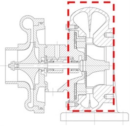
In this work, the JK90S turbocharger is adopted, which fixes to a 6-cylinder diesel engine, the assembly drawing of the turbocharger is shown in Fig. 1(a). The rated speed of the engine is 2400 r/min, corresponding to the pulsation frequency of 60 Hz. In this paper, the turbine stage is investigated, marking with the red dotted line regions in Fig. 1(a), including volute, guide vanes and rotor blades. For the rotor, the numbers of blades are 10, the inlet diameter is 83.5 mm, the outlet diameter is 73.5 mm, and the endwall clearance is 0.6 mm. For the nozzle, the numbers of vanes are 15 and the endwall clearance is 0.6 mm.
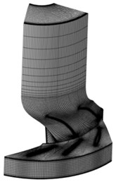
Considering the time-consuming and computing resources of the unsteady calculation with pulsation inlet conditions, the numerical model of turbine was simplified and the volute was neglected in CFD simulations, and the numbers of the rotor blade and nozzle vane were reduced to 2 and 3 respectively according to the blade reduction method of turbomachinery. The structured hexahedron multi-block topology was adopted to generate computation grids by numerical software. As shown in Fig. 1(b), the girds of single nozzle passage were about 150,000 and the numbers of single rotor blade passage grids were almost 250,000. The total grids numbers of turbine computation domain were about 1,000,000.
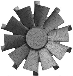
The material of impeller is chrome-nickel alloy, the density 8000 kg/m3, the Poisson ratio 0.3, the elastic modulus 2×10⁵ MPa, the ultimate yield strength 760 MPa. Solid187 element is used to generate the FE calculation grids, which has three degrees of freedom at each node: translations in the nodal , , and directions. The element has plasticity, stress stiffening, large deflection and large strain capabilities; it also has a quadratic displacement behavior and is well suited to model irregular meshes. The FE grids of the turbine were shown in Fig. 1(c). It was consisted of almost 90,000 tetrahedron elements. A modal eigen-value extraction of Block Lanczos method was performed to obtain the eigen-frequencies and mode shapes. In dynamic calculations, the turbine wheel shaft was cylindrical supported to load the rotational speed, the radial and axial direction were fixed, the tangential was free, and blades were fixed on the hub.
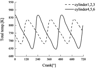
According to the test results of pulsation exhaust conducted by Dale and Watson [23], as shown in Fig. 2. It can be observed that the pressures and temperatures of the engine exhaust were changing with time, and the pulsation wave was similar to the sinusoid curve.
Fig. 1Models of turbine
a) Turbocharger
b) CFD grids of turbine
c) FEA grids of turbine
Fig. 2Pulsation exhaust features
a) Total pressure
b) Total temperature
In this work, the pulsating total pressure and total temperature were simulated by sinusoidal variation curves of total pressure/temperature and imposed at turbine inlet for the CFD calculations, as follow:
where, is transient total value, is the average value in pulsation cycle, is the amplitude, is the frequency. Here, the pulsation frequency is determined by the number of cylinders of the engine rotational speed.
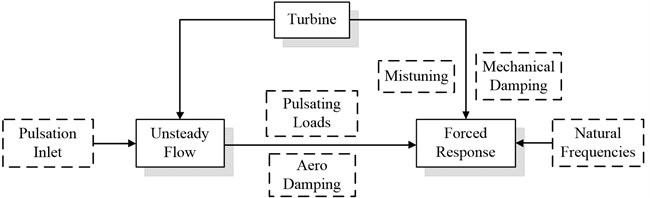
As illustrated in Fig. 3, the solutions of the fluid and structural equations are performed by the decoupled method. The unsteady flow of the turbine with pulsating inlet conditions, discussed above, is conducted by solving the RANS equations. The CFD analysis is performed not only to obtain the aerodynamic excitations due to unsteady interaction of pulsating flow in turbine internal, but also to get the aerodynamic damping ratio. Then, the aerodynamic loads are transformed from time domain to frequency domain by FFT. Harmonic vibration of the turbine is performed, with considering the aerodynamic excitations provided by periodic aerodynamic disturbances of pulsating flow, aerodynamic and mechanical damping and the mistuning issue of the blade disk. The natural frequencies and mode shapes of the turbine blade disk are obtained by modal analysis using the commercial FE solver. The forced response analysis including the harmonic vibration and transient structural response are conducted.
Fig. 3A schematic diagram of solution process
4. Results and discussion
4.1. Aerodynamic loading
The unsteady flow calculation of the turbine under pulsation inlet condition was performed using the numerical models and boundaries presented above. The numerical calculation process consumed more than 100 CPU time with 8 nodes parallel computation and took up more than 300 GB computer memory. Considering the numerical convergence criterion, the mass flows at inlet and outlet were monitored, and the difference is 1.485 %, which can be acceptable [24].
To observe the variation of aerodynamic loading on the blade surfaces in a pulsation cycle, three monitoring points were set at the leading edge of blade, which were the crossover points of 10 % chord and 0.1 span, 0.5 span, 0.9 span respectively. Fig. 4 shows the changes of blade loadings in a pulsation cycle at these three monitoring points. In the figure, the blade loading is defined by the static pressure difference between the PS and SS side. It can be seen that the aerodynamic loadings of blade are fluctuating with the change of pulsating inlet conditions. At various spans, the changes of blade loadings accord with the inlet pulsation conditions. The maximum and minimum blade loading respectively correspond to the peak and trough of inlet pulsation pressure. And the significant loading fluctuations are observed near the maximum and minimum point. The blade loading at high span is larger than that at low spans.
Fig. 4Blade loads in a pulsation cycle
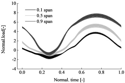
Fig. 5Pulsation inlet conditions
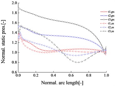
Fig. 5 shows the static pressures on the PS and SS at various typical pulsation time steps. In the figure, , , correspond to the wave trough, the equilibrium position and the wave peak of the pulsation inlet respectively. It can be seen that the pressure difference between PS and SS side at is the minimum, at is the maximum and at is the middle, which corresponds to the trough and peak locations of the inlet pulsation waves.
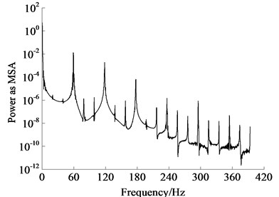
The FFT is conducted to transfer the blade loading from time-domain to frequency domain. The result of FFT contains the frequency data and the complex transformed results. Meanwhile, it can also provide the magnitude, amplitude, phase, power density and other computation results. The power density estimation can be made by three different methods: MSA, SSA and TISA. Fig. 6 and Fig. 7 shows the FFT results of blade loadings at 0.5 span, including the amplitude-frequency characteristics and MSA power density features. It can be seen that the low frequency characteristics of the blade loading are mainly reflected by the inlet pulsating frequency, especially for the one time and twice of the pulsating frequency. The power spectrum curve also shows the dominant role of the integral multiple of the pulsating frequency.
Fig. 6Amplitude-frequency characteristic
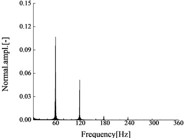
Fig. 7Power-frequency diagram
4.2. Natural frequencies and modes
The finite element analysis of turbine rotor were performed to extract the modal eigenvalues and to obtain the structure’s vibration behaviors. For the coupled blade disk of turbine, the vibration modes can be characterized by the node diameter lines of turbine wheel. Nodal diameter (ND) is used to describe the vibration characteristic of blade disk, and the detailed description can be referred by refs. [9, 11].
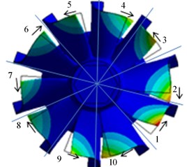
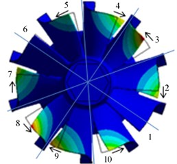
In this work, the blade number of turbine rotor is ten, and the maximum ND number is 5. Fig. 8 shows the first order mode shapes of the blade disk of turbine wheel in various NDs. In these figures, the blades are marked with 1, 2,…, 10; the blue lines passed through the center of turbine wheel present the nodal diameter lines; the non-deformed geometry wireframes are presented by black lines; the arrows show the move directions of mode deformations. It can be seen that the natural modes of the blade disk are various among different NDs. For ND 0, the mode shape with zero nodal diameters and all blades vibrate along the circumferential direction which shows an in-phase vibration. For ND 1 to ND 5, it can be observed that the movement directions of the mode deformation in both sides of the ND lines are opposed, and the deformation amplitudes are various. Blades located on the ND lines are not deformed, adjacent blades swing out of phase when separated by ND lines, such as in ND 4, blade 1 and blade 6 are almost still because they are situated at one of the ND lines. Meanwhile, blades close to the nodal points on the disk bear the maximum excitation accompanying with the maximum blade tip deformation, whereas blades at the antinodes are much less or even stand still.
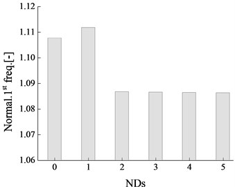
To further observe the blades mode deformations in various NDs, the mode deformations of blade tips are presented in Fig. 9. It can be seen that the deformations at blade tips are jumping in ND 1 to ND 5, but the mode deformations of blade 1 to blade 10 in ND 0 are almost keep the same. It is also can be found this phenomenon in Fig. 8. For ND 0, the vibration characteristics are conducted on the tuned blade disk and the modes of the blades is uniform. For ND 1 to ND 5, the mistuning effects cause the mode localization of the blade disk and the vibration differences among blades are generated, meanwhile, the mode deformation fluctuations among blades are also formed. Fig. 10 shows the first order natural frequencies of the turbine blade disk in various NDs, it can be seen that the frequency mistuning effects among various NDs are produced. Compared with ND 0, the natural frequency in ND 1 increases, but the frequencies in ND 2, ND 3, ND 4 and ND 5 decrease with the same amplitude of frequency.
Fig. 8Mode shapes of blade disk
a) ND 5
b) ND 4
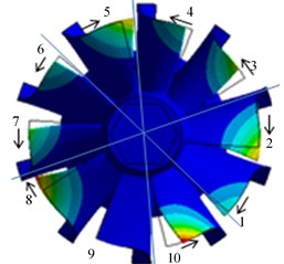
c) ND 3
d) ND 2
e) ND 1
f) ND 0
Fig. 9Blade tips deformations in various NDs
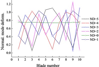
Fig. 10First natural frequencies in various NDs
4.3. Forced vibrations
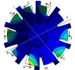
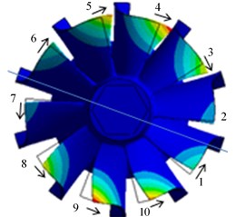
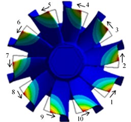
Based on the natural modes and frequencies of the blade disk, the harmonic vibration and transient response are performed to investigate the forced response behaviors of the turbine wheel, which are the combined results of the eigen-modes of the blade disk and the time-depended pressure fluctuations caused by the pulsation flow in turbine internal. For the harmonic vibration analysis, the pressure fluctuations are transformed from time domain to frequency domain by FFT method, and then the aerodynamic loadings are applied to harmonic vibration in FE method. Fig. 11 shows the calculated strains of rotor blades near the first natural frequency. It can be seen that the strains of the blades are with the pair due to the phase differences among the blades, such as, the strains of blade 1 and blade 6 are the same because the phase difference between them is 180°, similar regulars can be also observed from blade 2 and 7, blade 3 and 8, blade 4 and 9, blade 5 and 10. Meanwhile, the strains of the five pairs of blades are various due to the mode localization of the blade disk caused by traveling wave effects. To observe the effects of the phases on the harmonic responses of the blades, Fig. 12 shows the deformations of the blade disk in various phases at the first natural frequency. Obviously, the maximum deformations located at the phase of 90° and 270°, while the minimums are at 0° and 180°, which are according with the sinusoidal harmonic vibration.
Fig. 11Blade tips deformations in various NDs
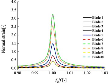
Fig. 12First natural frequency in various NDs
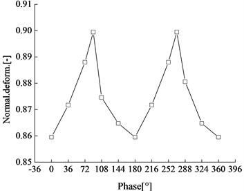
Fig. 13Transient deformations in a pulsation cycle
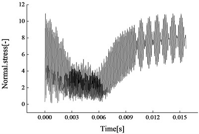
Fig. 14Transient stresses in a pulsation cycle
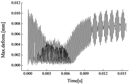
Further, the transient structural response of the blade disk is performed after putting the aerodynamic excitations and measured damping, combining with the natural frequency and mode. The deformations and the stresses of the blade disk in a pulsation cycle are presented in Fig. 13 and 14. It can be seen that both the transient deformations and the stresses and are changing with the pulsating pressure fluctuations. In a pulsation cycle, the deformations and the stresses of the blade disk are following by the pulsating wave of inlet condition. Meanwhile, the high frequency rotational characteristics of the turbine rotor are also reflected in the figures. The deformations and stresses are jumping in a rotor rotational cycle, and the time is shorter compared with pulsation steps. Therefore, the forced vibration of the blade disk in pulsation flow is not only affected by the low frequency pulsating excitation, but also affected by the high frequency excitation of rotor rotation due to the rotor-stator interaction, wake and potential flow.
5. Conclusions
The work in this paper investigated the aerodynamic excitation and the forced vibration of a automotive turbocharger turbine with the variable guide vanes under pulsation inlet conditions. A pulsation flow with the frequency of 60 Hz was applied at the turbine inlet according to the exhaust of the engine and the unsteady calculation of the turbine was performed. The calculation process consumed more than 100 CPU time with 8 nodes parallel computations and took up more than 300 GB computer memory. The results of the unsteady flow in turbine internal demonstrated the aerodynamic loads of the blades are highly influenced by the pulsation inlet conditions, which follow the change of the inlet pulsation wave, in a pulse cycle, the maximum and minimum corresponding to the peak and trough of the pulsation inlet respectively.
A detailed analysis for the natural dynamic behaviors of the turbine wheel was conducted, especially, the first order natural mode was paid special attentions. The results of the eigen mode of the blade disk show that nodal diameter vibrations appear in pairs, marked with ND 0, ND 1, ND 2, ND 3, ND 4 and ND 5. Compared with ND 0, the vibration modes in other NDs are separated by their ND lines, and the deformations of the natural vibration are various. The phases among the blades significantly affect the vibration of turbine blade disk. Blades close to the nodal points on the disk bear the maximum excitations accompanying with the maximum blade tip deformations, whereas blades at the antinodes are much less or even stand still. The maximum stress caused by the first order vibration locates at the trailing edge of the blade.
The forced vibration calculations of the turbine blade disk, including the harmonic vibration and transient structural response were performed based on the calculated aerodynamic loads in pulsation flow and the natural modes of the blade disk. The harmonic responses of the blades obey the nodal diameter vibration characteristics of the blade disk and separated by the ND line. The deformation responses of the blades with the phase difference of 180° have the same response trend and present in pairs, such as, blade 1 and 6, blade 2 and 7, blade 3 and 8, blade 4 and 9, blade 5 and 10. The results of the transient structural response of the blade disk show that forced response of the blade disk not only contains the contribution of the low frequency excitations of the pulsation flow but also reflects the high frequency pressure fluctuations of rotor rotation.
References
-
Nguyen-Schäfer H. Rotordynamics of Automotive Turbochargers. Springer Berlin Heidelberg, 2012, p. 33-57.
-
Kulkarni A., Larue G. Vibratory response characterization of a radial turbine wheel for automotive turbocharger application. ASME Turbo Expo, No. GT2008-51355, 2008.
-
Gnesina V. I., Kolodyazhnaya L. V., Rzadkowski R. A numerical modelling of stator-rotor interaction in a turbine stage with oscillating blades. Journal of Fluids and Structures, Vol. 19, 2004, p. 1141-1153.
-
Winterbone D., Nikpour B., Alexander G. Measurement of the performance of a radial inflow turbine in conditional steady and unsteady flow. Proceedings of the 4th International Conference on Turbocharging and Turbochargers, 1990.
-
Szymko S., Martinez-Botas R. F., Pullen K. R. Experimental evaluation of turbocharger turbine performance under pulsating flow conditions. ASME Turbo Expo, No. GT2005-68878, 2005.
-
Lam J., Roberts Q., McDonnell G. Flow modelling of a turbocharger turbine under pulsating flow. 7th International Conference on Turbochargers and Turbocharging, 2002, p. 181-196.
-
Palfreyman D., Martinez-Botas R. F. The pulsating flow field in a mixed flow turbocharger turbine: an experimental and computational study. Journal Turbomachinery, Vol. 127, Issue 1, 2005, p. 144-155.
-
Padzillah M. H., Rajoo S., Martinez-Botas R. F. Numerical assessment of unsteady flow effects on a nozzled turbocharger turbine. ASME Turbo Expo, No. GT2012-69062, 2012.
-
Liu Y. X., Yang C., Ma C. C., Lao D. Z. Forced responses on a radial turbine with nozzle guide vanes. Journal of Thermal Science, Vol. 23, Issue 2, 2014, p. 138-144.
-
Hans-Jorge B., Achmed S. Aerodynamic excitation of blade vibrations in radial turbines. Research on Vibration, Vol. 74, 2013, p. 48-54.
-
Filsinger D., Sekavcnik M., Ihli T., Schulz A., Wittig S. Vibration characteristics of a radial turbocharger impeller. 7th International Conference on Turbochargers and Turbocharging, 2002, p. 117-127.
-
Ewins D. J. Vibration modes of mistuned bladed disks. Journal of Engineering for Power, Vol. 98, Issue 3, 1976, p. 349-355.
-
Sinha A. Statistics of the peak maximum amplitude of the forced response of a mistuned bladed disk. ASME Turbo Expo, No. GT2005-69070, 2005.
-
Sinha A. Computation of eigenvalues and eigenvectors of a mistuned bladed disk. ASME Turbo Expo, No. GT2006-90087, 2006.
-
Hemberger D., Filsinger D., Bauer H. Investigations on maximum amplitude amplification factor of real mistuned bladed structures. ASME Turbo Expo, No. GT2012-68084, 2012.
-
Hemberger D., Filsinger D., Bauer H. Mistuning modeling and its validation for small turbine wheels. ASME Turbo Expo, No. GT2013-94019, 2013.
-
Hemberger D., Filsinger D., Bauer H. Source of mistuning identification for casted wheels of small size. ASME Turbo Expo, No. GT2014-25099, 2014.
-
Hattori H. Study on mistuning identification of vehicle turbocharger turbine blade disk. ASME Turbo Expo, No. GT2014-27217, 2014.
-
Filsinger D., Schäfer O., Szwedowicz J. Approach to unidirectional coupled CFD-FEM analysis of axial turbocharger turbine blades. ASME Turbo Expo, No. GT2001-0288, 2001.
-
Filsinger D., Frank C., Schäfer O. Practical use of unsteady CFD and FEM forced response calculation in the design of axial turbocharger turbines. ASME Turbo Expo, No. GT2005-68439, 2005.
-
Giersch T., Honisch P., Beirow B., Kuhhorn A. Forced response analyses of mistuned radial inflow turbines. Journal of Turbomachinery, Vol. 135, 2013, p. 031034.
-
Yang M. T., Griffin J. H. A reduced-order model of mistuning using a subset of nominal system modes. Journal of Engineering for Gas Turbines and Power, Vol. 123, 2001, p. 893-900.
-
Dale A. P., Watson N. Vaneless radial turbocharger turbine performance. Turbocharging and Turbochargers, ImechE, 1986, p. 65-76.
-
Chen L., Zhuge W. L., Zhang Y. J., Li Y. Z, Zhang S. Y. Investigation of flow structure in a turbocharger turbine under pulsating flow conditions. SAE International Journal of Fuels and Lubricants, Vol. 1, Issue 1, 2008, p. 1167-1174.
About this article

The work was funded by National Natural Science Foundation of China (No. 51276017).
