Abstract
The combined dynamic characteristics of the centrifugal pump induced by the fluid and motor excitation forces are investigated in this paper. The coupling vibrations of a centrifugal pump during the operation are mainly caused by the fluid excitation and the motor excitation forces. The finite element model was constructed in this paper under the consideration of the fluid excitation which was obtained from the numerical simulation and the motor excitation force which came from the experiments; compared with the experimental results and well agreement, the components of the whole model were validated to be accurate enough for simulation. Applying the approach of the modal dynamics, the dynamic analysis was conducted to study the influence of the flow rate, the blade number, the exit installation angle and the outside diameter of impeller on the responses. The suggested optimal parameters were provided from the perspective of the vibration reduction. The results of the calculation are helpful to the designation and the safe operation of the centrifugal pumps.
1. Introduction
Centrifugal pump is a type of rotary fluid machinery. The working fluid gets the energy from the rotating blades during its operation; and then the working fluid excites the body of pump and the shaft of rotation by means of an unsteady pressure. This excitation leads to a coupling vibration of sound field within the pump and structural response. The vibration and noise propagate outward along the pipeline. The mechanical noise is directly related with the pump, for example from the bearings and the sealing elements. However, the mechanical noise is not significant unless there is a mechanical fault existing. The fluid dynamic noise mainly comes from the interior of the pump shell and it is directly related with the unsteady pulsating flow within the pump. This kind of vibration and noise affects the performance of the machinery system. Therefore, the investigation of the vibrational characteristics for the centrifugal pump is meaningful for the engineering application.
The excitation which causes the vibration of the centrifugal pump originates from three facets; the first facet is an excitation of the same frequency for the rotation due to the mass asymmetry of the rotating shaft, impeller and other accessories; the second facet is the periodic transitive moment and torque due to the misalignment of the engine shaft and the rotor shaft; the third is the unsteady fluid excitation within the centrifugal pump. The influence degree of the three excitations on the vibration of centrifugal pump depends on the working condition. The mechanism of the structural vibration induced by the asymmetry and misalignment has been studied deeply. During the last decades, much progress has been obtained about the vibration of the centrifugal pump. C. G. Rodriguez [1] et al. carried out a theoretical analysis to predict and explain in a qualitative way the frequencies and amplitudes for the rotor stator interaction in a centrifugal pump turbine. A successful corrective action is proposed as a consequence of this new interpretation. Y. Y. Jiang et al. [2] reported on a full-scale structural simulation of flow-induced mechanical vibrations and noise in a 5-stage centrifugal pump. They clarified the mechanisms of the resonant vibration and the noise generation and propagation, which can then be used for noise reduction. Andreas Lucius et al. [3] researched on the velocity fluctuations during rotating stall of a centrifugal pump in order to determine their importance for excitation of structural vibrations. Lohasz M. et al. [4] and Byskov R. et al. [5] applied the large eddy simulation in the field of turbomachinery to solve more details of the flow field and restricted to low Reynolds numbers. In addition, the hybrid methods [6-9] like detached eddy simulation are used increasingly. Many researchers [10-14] studied the fault diagnoses of the centrifugal pump or rotational machinery. Zhou Yunlong and Zhao Peng [15] proposed a new fault diagnose method for the nonlinear and non-stationary characteristics of the vibration signals of centrifugal pump based on complexity feature of Empirical Mode Decomposition (EMD). While V. Muralidharana et al. [16] carried out an investigation of fault diagnose for the monoblock centrifugal pump using the support vector machine (SVM) and artificial neural networks were employed for continuous monitoring and fault diagnosis. R. Barrioa et al. [17] explored the use of a commercial CFD code to estimate the total radial load. Liu Hou-lin et al. [18] studied the unsteady attached sheet-cavitating flows in a centrifugal pump by experimental investigation and numerical analysis. Even though the mass unbalance is difficult to be eliminated completely, the dynamic balance technology is applied to decrease the influence of the mass unbalance for a minor excitation force. For the rotor misalignment, the periodic excitation force can be effectively decreased if the flexible connections are applied to the junctions of the two rotors. Based on the modal dynamics method, Nan et al. [19] studied the influence of some parameters on the vibrations of the centrifugal pump only under the consideration of fluid excitation.
The motor excitation is a causation of the vibration and noise and it has not been eliminated effectively at present. Therefore, the construction of the centrifugal pump model and the study of the combined vibrational characteristics are essential for the theory and engineering application. Dynamic characteristics of centrifugal pump induced by the fluid and motor excitation forces have studied rarely in the published articles, this research will be reported in this paper.
2. Modal dynamics method
The modal dynamics are applied in this paper to calculate the responses. Modal dynamics method is an analytical approach for the transient dynamics, including implicit dynamics analysis, subspace explicit dynamics analysis, explicit dynamics analysis and modal dynamics analysis. This method applies the modal superposition method to solve the transient responses of the linear system. The characteristic modes should be extracted before this method based on the characteristic modes is applied. The method is adopted to make the time-domain analysis of a linear system, where the excitation is a function of time and there is an assumption that the amplitude in every incremental time step is linear under the determined excitation. Projecting the physical model to the characteristic modal coordinate system leads to a set of equation of motion:
where means the critical damping ratio; is the kinematic variable under the modal coordinates; is the circular frequency of the un-damped vibration; is the modal force and is the increment of the modal force with . The solution of Eq. (1) is formulated as:
The non-rigid solution of Eq. (2) is divided as three situations by damping:
a) It is the common sense that the damping is less than the critical damping, in this case, it is under damping, the coefficients in Eq. (2) are as follows:
b) The damping is equal to the critical damping, in this case, , it is critical damping.
c) The damping is over critical damping, . For the case B and C, the coefficients and can be derived.
Integrating the equation of motion to time leads to the dynamic response under the modal coordinate and then the physical response of coordinate can be obtained by mode superposition:
where , , and represent modal shape, modal stain, modal stress and modal reaction force, respectively. Using the modal dynamic method, the transformation of the initial displacement and the initial velocity is determined by:
where , and represent the generalized mass, shape and mass matrix, respectively.
3. Modelling and validation
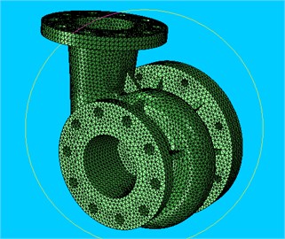
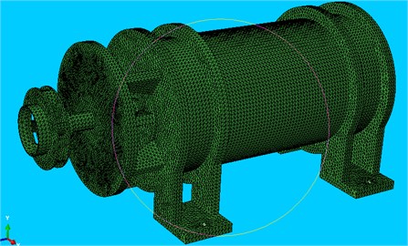
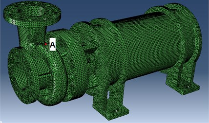
Importing the geometry model into the Software Abaqus and then meshing the components by using the type of C3D4 lead to the analytical model, as seen in Fig. 1(a), (b). Different types of elements and different dimensions are applied for different parts in order to get the fined geometry features. The quality of the element is checked for a good quality and re-meshed the part if the quality does not meet the requirements until the quality is good enough for calculation. The coefficients used are: Modulus of elasticity 210 GPa, density 7850 Kg/m3, Poisson ratio 0.3. After calculating the free modal of the components, comparing the results with that of experiments, they agree well, as seen in Table 1.
The connection between the two components in centrifugal pump mainly includes the bolting, the shaft coupling and so on. The springs with the different stiffness coefficients are adopted to simulate the connections in this paper. The absorber on the frame and the connections between the inlet/outlet pipe with the exterior are also simulated as the spring with certain stiffness coefficients, but the type of these springs is connecting point to ground. The springs are built with different types and different stiffness under the consideration of the stiffness in three directions in order to be closer to reality.
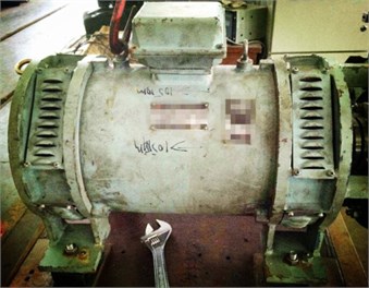
Fig. 1a), b) The FE model of the main components for the pump, c) experimental figure
a)
b)
c)
Table 1Comparison of the FE results with experiments for the 1st natural frequency
Components | Experiments (Hz) | Fem (Hz) | 1st natural frequency error (%) |
Volute | 911 | 888 | –2.5 |
Pump lid | 2682 | 2640 | –1.6 |
Overall machine | 282 | 281 | –0.3 |
For the fluid FEM mesh, the dividing region mesh method is adopted to mesh for an ideal topology structure; the local mesh encryption technology is applied to the wall of the blade, the impeller and the vortex tongue for a better mesh quality. The hex grid structure is employed in the computational domain; the total number of the elements is about 2,900,000, as shown in Fig. 2.
4. Results and analysis
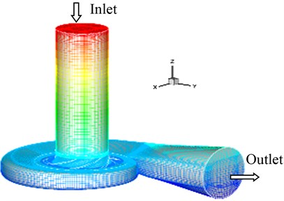
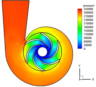
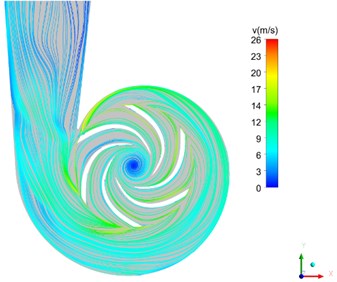
The response on the volute under the fluid excitation which comes from the numerical simulation and the motor excitation which is obtained from the experiments will be investigated in this paper. The unsteady flow in the centrifugal pump induces the noises and the vibrations. With the help of the CFD and Fluent, the steady and the unsteady flow of the channel with the impeller and the volute are calculated to obtain the internal pressure field and the streamline distribution, as seen in Fig. 3.
The constrained modes of the centrifugal pump which are connected with the inlet/outlet pipe are calculated before the responses are computed. Applying the spring (connect point to ground), the feet of the machine, the inlet and the outlet are joined by springs to the ground. The constrained modes are calculated by using the Lanczos Method; the results are seen in Table 2; and the 1st and 2nd modes are shown in Fig. 4.
Fig. 2The schematic diagram for the fluid FEM mesh of the centrifugal pump

a) Impeller mesh
b) Global mesh of fluid FEM model
Fig. 3a) The internal pressure field and b) the streamline distribution for the 50 % blade height plane (blade number = 6)
a)
b)
Fig. 4a) The first mode and b) the second mode
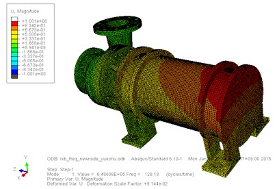
a) 1st mode
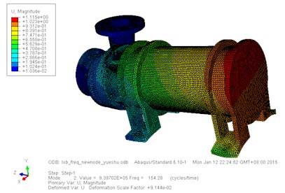
b) 2nd mode
In order to study the effect of the flow rate, impeller number, impeller outside diameter, exit installation angle on the response of the analytical point, the number of the impeller is selected as: 4 blades, 5 blades, 6 blades, 7 blades and 8 blades, respectively; the outside diameter of the impeller is selected as: 170 mm, 171 mm, 172 mm, 173 mm and 174 mm, respectively; the exit installation angle is 20°, 23°, 27°and 35°, respectively. The point on the volute A is selected as the analytical point of the response, as seen in Fig. 5. Thereupon then, the response signal of the analytical point is extracted for analysis.
Table 2The main constrained mode (constrained on the inlet, outlet and the feet of the machine)
Order number | Frequency (Hz) |
1 | 128.18 |
2 | 154.28 |
3 | 184.43 |
4 | 282.95 |
5 | 301.85 |
6 | 343.89 |
7 | 363.71 |
8 | 384.88 |
9 | 617.03 |
10 | 686.75 |
Fig. 5The analytical point of the response (red point A)
4.1. The influence of the flow rate on the vibrations
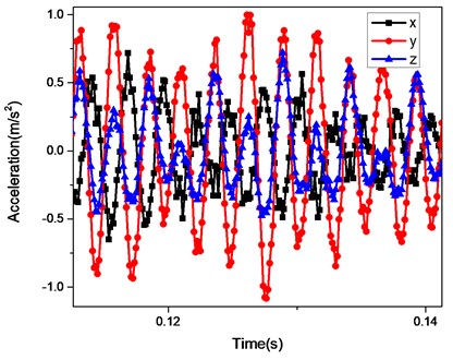
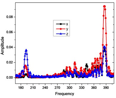
The fluid excitation and motor excitation are exerted to study the effect of the excitation on the dynamic response. The flow rate is the liquid quantity delivered in unit time; it is the fundamental parameter of the performance for the centrifugal pump. The influence of the flow rate on the vibration is investigated in this section. Fig. 6 shows the time history and Frequency-Response curves for the analytical point. The FR curves show the response for the , and components; and it can be seen from the curves that the three components have the same peak value of response 291 Hz.
Fig. 6a) The time history and b) FR curve (6-Blade, outside diameter174 mm, flow rate 0.6)
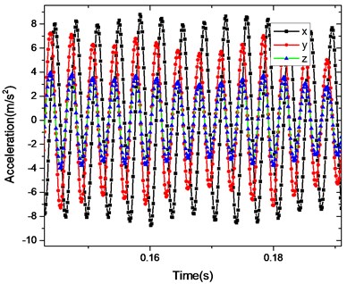
a)
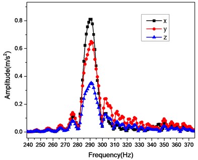
b)
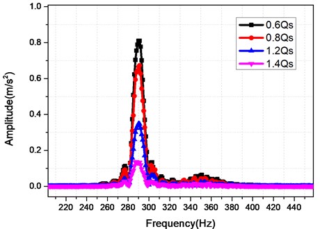
Fig. 7 shows the FR curves for the analytical point with the different flow rate 0.6 Q, 0.8 Q, 1.2 Q and 1.4 Q. It can be seen from Fig. 7 that the acceleration responses of the analytical point for the centrifugal pump decreases with the increasing of the flow rate; the different flow rates excite the same resonant frequency 291 Hz.
Fig. 7The influence of the flow rate on the FR curves
4.2. The influence of the blade number on the vibrations
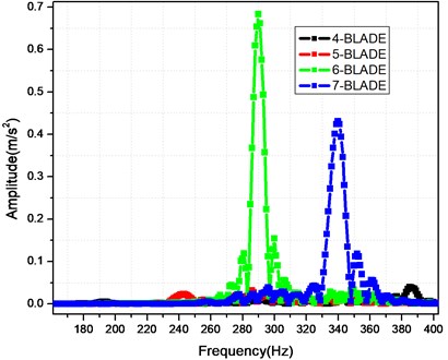
The blade number is the important parameter of the centrifugal pump. Fig. 8 shows the time history and Frequency-Response curves for the analytical point of the 4-blade. The FR curves show the FR curves for the , and components; and the three components have the same peak value of response 386 Hz. Fig. 9 shows the FR curves for the analytical point with the different blade number 4-blade, 5-blade, 6-blade and 7-blade. It can be seen from Fig. 9 that the max acceleration responses of the analytical point is for the 6-blade, while the minimal acceleration is for the 5-blade; the frequency multiplication 193 Hz, 242 Hz, 290 Hz and 338 Hz, which are the multiplications of the shaft frequency 48.3 Hz, appear for the blade number 4-blade, 5-blade, 6-blade and 7-blade, respectively; the frequency of the response peak is 386 Hz, 296 Hz, 290 Hz, 340 Hz for the 4-blade, 5-blade, 6-blade and 7-blade, respectively. Therefore, the optimal number of the blade is 5-blade only under the consideration of the vibration reduction. The resonant frequency and the reducing vibration should be considered comprehensively in selecting the blade number.
Fig. 8a) The time history and b) FR curve for the analytical point (4-blade)
a)
b)
Fig. 9The influence of the blade number on the FR curves
4.3. The influence of the exit installation angle on the vibrations
The exit installation angle is an essential parameter of the centrifugal pump. The exit installation angles are selected as 20°, 23°, 27°, 30° and 35°. The influence of them on the vibrations is shown in Fig. 10. It can be seen from Fig. 10 that the different angles have the same resonant frequency 290 Hz; and the maximal amplitude is for the 30° while the minimal amplitude is for 20°.
Fig. 10The influence of the exit installation angle on the FR curves
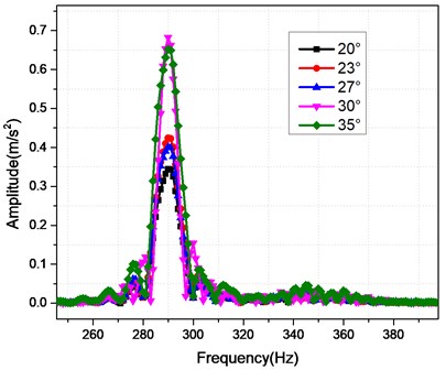
Fig. 11The influence of the outside diameter on the FR curves
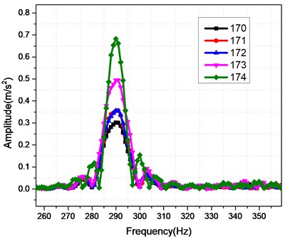
4.4. The influence of the outside diameter on the vibrations
The outside diameter of the impeller for the centrifugal pump has effect on the dynamic characteristics of the system. The outside diameters of the impeller are selected as 170 mm, 171 mm, 172 mm, 173 mm and 174 mm. The influence of them on the vibrations is shown in Fig. 11. It can be seen from Fig. 11 that the different outside diameters have the same resonant frequency 290 Hz; and the maximal amplitude of the response is for the 174 mm while the minimal amplitude is for 170 mm; the diameter 171 mm and 172 mm almost have the same amplitude. Accordingly, the design of the outside diameter should consider the response to get a better damping; in this calculation example, the 170 mm is the better selection only from the vibration reduction.
5. Conclusions
The finite element model was built in this paper with consideration of the motor excitation and the fluid excitation forces. The analysis is conducted to study the influence of the flow rate, the blade number, exit installation angle and impeller outside diameter on the dynamic characteristics. The conclusions of the calculation are as follows:
1) The acceleration responses of the centrifugal pump decreases with the increasing of the flow rate; the different flow rates excite the same resonant frequency 291 Hz.
2) The optimal number of the blade is 5-blade under the consideration of the vibration reduction. The resonant frequency and the reducing vibration should be considered comprehensively in selecting the blade number.
3) The different angles have the same resonant frequency 290 Hz; and the maximal amplitude is for the 30° while the minimal amplitude is for 20°.
4) The design of the outside diameter should consider the response to get a better damping; in this calculation example, the 170 mm is the better selection only from the vibration reduction.
References
-
Odriguez C. G., Egusquiza E., Santos I. F. Frequencies in the vibration induced by the rotor stator interaction in a centrifugal pump turbine. Journal of Fluids Engineering, Vol. 129, Issue 11, 2007, p. 1428-1435.
-
Jiang Y. Y., Yoshimura S., Imai R., Katsura H., Yoshida T., Kato C. Quantitative evaluation of flow-induced structural vibration and noise in turbomachinery by full-scale weakly coupled simulation. Journal of Fluids and Structures, Vol. 23, 2007, p. 531-544.
-
Lucius Andreas, Brenner Gunther Numerical simulation and evaluation of velocity fluctuations during rotating stall of a centrifugal pump. Journal of Fluids Engineering, Vol. 133, Issue 8, 2011, p. 081102.
-
Lohasz M. M., Nagy L., Wurm H. LES of the transitional flow in a miniature centrifugal pump. Proceedings of the 14th Conference on Modelling Fluid Flow, 2009.
-
Byskov R., Jacobsen C., Pedersen N. Flow in a Centrifugal pump impeller at design and off-design conditions – part 2: large eddy simulations. Journal of Fluids Engineering, Vol. 125, 2003, p. 73-83.
-
Feng J., Benra F.-K., Dohmen H. Unsteady flow visualization at part-load conditions of a radial diffuser pump: by PIV and CFD. Journal of Visualization, Vol. 12, Issue 1, 2009, p. 65-72.
-
Martini P., Schulz A., Bauer H.-J., Whitney C. Detached Eddy simulation of film cooling performance on the trailing edge cutback of gas turbine airfoils. Journal of Turbomachinery, Vol. 128, Issue 2, 2006, p. 292-299.
-
Iwakiri K., Furukawa M., Ibaraki S., Tomita I. Unsteady and three-dimensional flow phenomena in a transonic centrifugal compressor impeller at rotating stall. Proceedings of the ASME Turbo Expo, Vol. 7, 2009, p. 1611-1622.
-
Lucius A., Brenner G. Unsteady CFD simulations of a pump in part load conditions using scale-adaptive simulation. International Journal of Heat and Fluid Flow, Vol. 31, 2010, p. 1113-1118.
-
Sakthivel N. R., Nair Binoy B., Sugumaran V. Soft computing approach to fault diagnosis of centrifugal pump. Applied Soft Computing, Vol. 12, Issue 5, 2012, p. 1574-1581.
-
Sakthivel N. R., Sugumaran V., Babudevasenapati S. Vibration based fault diagnosis of monoblock centrifugal pump using decision tree. Expert Systems with Applications, Vol. 37, Issue 6, 2010, p. 4040-4049.
-
Wang Shengwei, Cui Jingtan Sensor-fault detection, diagnosis and estimation for centrifugal chiller systems using principal-component analysis method. Applied Energy, Vol. 82, Issue 3, 2005, p. 197-213.
-
Zhao Yang, Wang Shengwei, Xiao Fu A statistical fault detection and diagnosis method for centrifugal chillers based on exponentially-weighted moving average control charts and support vector regression. Applied Thermal Engineering, Vol. 51, Issues 1-2, 2013, p. 560-572.
-
Sakthivel N. R., Nair Binoy B., Elangovan M., Sugumaran V., Saravanmurugan S. Comparison of dimensionality reduction techniques for the fault diagnosis of mono block centrifugal pump using vibration signals. Engineering Science and Technology, an International Journal, Vol. 17, 2014, p. 30-38.
-
Zhou Yunlong, Zhao Peng Vibration fault diagnosis method of centrifugal pump based on EMD complexity feature and least square support vector machine. Energy Procedia, Vol. 17, 2012, p. 939-945.
-
Muralidharana V., Sugumaranb V., Indirac V. Fault diagnosis of monoblock centrifugal pump using SVM. Engineering Science and Technology, an International Journal, Vol. 17, 2014, p. 152-157.
-
Barrioa R., Fernándezb J., Blancoa E., Parrondoa J. Estimation of radial load in centrifugal pumps using computational fluid dynamics. European Journal of Mechanics B/Fluids, Vol. 30, 2011, p. 316-324.
-
Liu Hou-lin, Liu Dong-xi, Wang Yong, Wu Xian-fang, Wang Jian, Du Hui Experimental investigation and numerical analysis of unsteady attached sheet-cavitating flows in a centrifugal pump. Journal of Hydrodynamics, Vol. 25, Issue 3, 2013, p. 370-378.
-
Nan G., Zhang Y. Influence of parameters on vibrations for centrifugal pump based on the modal dynamics method. International Conference on Applied Science and Engineering Innovation, 2015.
About this article

The authors are grateful to the financial support of the National Science Foundation of China (Granted No. 51305267).
