Abstract
This paper presents theoretical contributions for the flexural vibration analysis of the Rayleigh beam having an edge crack with either symmetrical/asymmetrical two sided axial progressions (T shaped crack) or one sided axial progression (L shaped crack). Cracks are modelled as breathing that covers the conditions of open and closed crack cycles during the vibration of the beam. The energy release formulations given in fracture mechanics are rearranged to obtain the energy consumed due to the cracks considered. Natural frequencies of the beams with T and L shaped cracks are calculated by the Ritz’s approximation method that employs a continuous model of balanced energy distribution. Results of the method proposed are compared by the results obtained by the finite element (FE) analysis. Good agreements are achieved for several case studies including various axial progression lengths, depths, and locations of the crack.
1. Introduction
Crack occurrence in a beam element may bring about catastrophic failures for machines or structures that include lots of such elements under dynamic effects. Since the vibration characteristics of the elements instantaneously change with any damages, accurate identification of these characteristics is crucially important in respect of vibration based crack detection. The studies presenting the methods based upon vibration analyses are summarized in several overview papers [1, 2].
In literature, vibration analyses of beams with transverse edge cracks, which are considered as slots, have become main subject of many studies since early 1970’s [3-11]. Although most of the researchers use simplified crack model that is assumed to be propagated in cross-sectional plane, it is definite that real cracks grow with its own random way which varies based upon the strength of beam material in front of the crack tip. Transverse cracks can be approximately accurate when the crack propagates into beam around the cross-sectional plane passing from the crack mouth. However, the assumption of transverse slot cannot be true if the crack dominantly progresses in the axial direction.
Except for the transverse cracks, a few papers are introduced for the vibration analysis of homogeneous metallic beam with a unique crack. One of them can be the axial crack that does not open to the stressed or strained surfaces of the beam [12, 13]. On the other hand, axial cracking can be handled as interface crack that most likely exists on layered composite beams. Typical example for the interface crack can be the delamination of the beam whose vibrational effects are regularly studied by the researchers [14, 15]. The cases such as double edge [11], height-edge [16], inclined edge [17] and internal [18] cracks are also demonstrated as unique crack cases for vibrating beam. To the best of author’s knowledge, there is no research work addressing the vibration analysis of the metallic beam with a novel case of the edge crack that starts in cross-sectional plane and progresses in axial direction.
Numerous methods comprising analytical or numerical solutions have been proposed for the vibration analyses of the beams with transverse cracks. Most of the analytical solutions use rotational spring model to define local flexibility changes and compatibility conditions at the crack locations [3-7]. Apart from this, usage of energy based solution methods employing the continuous flexibility approach have significantly increased in recent years [8-11]. Continuous flexibility can be supplied by defining crack caused energy lost distributed through the beam. The usage of continuous flexibility model can be more appropriate for the axially progressed crack, since the cross-section with increased flexibility widens along the axial progression.
In this paper, vibration analysis of the beam with an edge crack progressed in axial direction is presented. Not only T shaped crack cases, but also the scenarios for L shaped crack and for the crack with asymmetrical progressions in axial direction are taken into consideration. The energy release formulations that are given for stressed element with T shaped crack progressed through short span of axial direction are extended for bending beam with the cracks progressed through much longer span. Breathing crack model makes the accurate result possible for long span of axial crack progression. As a result, effects of these cracks on natural frequencies are computed by Ritz’s solution method employing the distribution of the energy balance.
2. Theoretical analyses
Energy balance method of fracture mechanics is utilized in theoretical analyses. The energy release of stressed beam with an axially progressed edge crack is described as follows [19]:
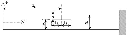
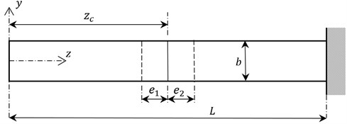
where and are the lengths of axial crack progressions in right and left hand sides, respectively. Fig. 1 shows all of the dimensions related to cantilever beam with the crack discussed as an example. is called the strain energy release rate that can be formulated as . symbolizes modulus of elasticity, , for plain stress, or for plain strains where denotes Poisson’s ratio. is the stress intensity factor calculated for total effects of Mode I and Mode II crack surface displacements given as follows [19]:
where is the coefficient varying with the ratio :
and is the symbolic of the maximum stress that is formulated as:
where and are height and width of the beam, respectively. is the bending moment varying along beam length coordinate, :
and denote the moment of inertia and transverse displacement, respectively. As a result, the energy release due to the crack specified can be generalized as follows:
where, is shortened notation used instead of following equation:
Fig. 1Dimensions of the beam with a T shaped crack
Tada et al.[19] present that the accuracy of their energy balance equation is better than 1 % for shaped crack cases providing where This restriction allows considering very small values of e for the cracks in thin beam. One may expect that breathing crack effects increase and become non-ignorable when the axial crack propagates further. Breathing cracks have open and closed phases that cause varying energy release during a period of vibration. As a result, since the energy release is minimized in closed phases, rising rate of energy release is expected to decrease with increasing axial crack length. Breathing crack effect can be simply contributed to Eq. (6) by making following modification:
where is the extension to the energy release providing admissible accuracy for :
Clapeyron’s Theorem states that while one half of the work done by external moment is transformed into additional stress/strain energy around the crack tip, the other half should be the energy released. Therefore, crack based energy release is equal to the change in strain/stress energy which is maximum around the crack tip and exponentially decays toward the ends of the beam. Two different maximum energy release points exist around the crack tips whose locations vary with axial progression length. Throughout the un-cracked cross-sections of the beam, energy releases are distributed in following form [10, 11]:
where and can be defined as follow:
Eq. (10) describes the energy release distribution that is originated from the crack propagated toward one of directions. Note that energy releases due to both Mode 1 and Mode 2 crack surface displacements are taken into account. However, it does not contain the effects of stressed/strained cross-sections varying part by part during the cycles of bending vibration. Therefore, the distribution form should be rearranged part by part for both open and closed phases of the crack.
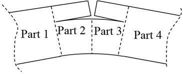
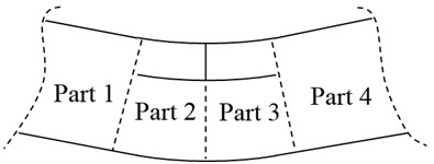
Fig. 2a) Open and b) closed phases of the crack
a)
b)
Open and closed phases of the edge crack progressed along left and right hand sides of a bending beam are exaggeratedly illustrated in Fig. 2. When the crack is in the open phase during the first cycle of vibration, stress/strain effects of the cracked parts separated from the beam can be neglected. It is for this reason that the energy release distribution caused by the crack propagated toward left side should be multiplied by for the parts 2, 3, and 4. On the contrary, the distribution come into existence due to the crack propagated toward right side should be multiplied by for the parts 1, 2, and 3. Secondly, even if the cracked parts are stressed during the closed phases of cracks, stress waves cannot pass over the edge of crack. In this case, multiplication is applied for the parts 3 and 4 due to the energy releasing from the crack tip at the left side and vice versa. All these distributions can be superposed to obtain total energy release distribution, , considered part by part as follows:
where the subscripts “”, “”, “”, “”, and “” are the abbreviations of the words “part”, “left crack”, “right crack”, “open phase” and “closed phase”, respectively. Since the work is done using the available maximum potential energy, the crack based energy release results in a decrease of maximum potential energy with the assumption that there is no mass loss at the crack location. Thus, the energy balance, , can be formulated by using the conservation of energy law as follows:
and represent the distributions of the maximum potential and kinetic energies as follow:
In the equation of potential energy distribution, moment of inertia, , should be modified by taking the reduced cross-section into account throughout axially cracked parts 2 and 3. In Eq. (16), the second term describes the effect of rotary inertia that is included by the Rayleigh beam. According to the Ritz’s approximation method, the derivatives of energy balance with respect to coefficient of admissible mode shape function, , should be equal to zero:
If are a series of functions satisfying the end conditions, the mode shape function can be written as:
It is well known that the natural frequencies are singular values of the matrix formed by the coefficients of function series. These series vary with the end conditions whose general cases are given in Table 1.
Table 1Series of functions satisfying general end conditions
End conditions | |
Fixed-fixed | |
Pinned-pinned | |
Fixed-free | |
Fixed-pinned |
3. Results and discussion
In this section, the vibration theory proposed for the beam with either T or L shaped edge crack is verified using the beam modelled by the commercial finite element (FE) package (Ansys©). Comparative studies have been implemented on an aluminum alloyed cantilever beam having square cross-sectional area of 0.01×0.01 m2 and length of 0.36 m. Modulus of elasticity, density and Poisson ratio of the beam are given as 69 GPa, 2678 kg/m3, and 0.3, respectively. The beam has been modelled by the FE package using the element type “solid95” that covers 20 nodes per element. It is slotted using subtracting slender blocks to form axially progressed edge cracks. Crack width, 0.0003 m, is designated as thin as possible so that sufficient sensitivity is provided without the need of unnecessarily long solution time. Default element size is set to 0.0045 m which causes separation of the smallest edge with two elements. The beam is smartly meshed using refined elements for increasing the sensitivity of free meshing procedure in the vicinity of crack. An example for meshing view around T shaped crack is shown in Fig. 3. As a result, natural frequencies are obtained by using modal analysis tool of the package. It should be noted that the number of elements, which varies with the location and the size of crack, has negligible effects on the results.
Un-cracked beam’s natural frequencies are tabulated in Table 2 which shows good agreement of the frequencies obtained by the Ritz’s approximation and the FE analysis. Results of the approximation and the FE analysis also need to be compared with each other for several cracked beam cases to inspect the success of present approach. In this respect, vibration analyses of cracked beams are performed to verify proposed crack related formulations. Cases including variety of crack locations, crack depths, and axial crack progressions are listed below:
Case 1: 0.2, , 0.2, , variable.
Case 2: , , , variable, .
Case 3: variable, , , , .
Case 4: , , , variable, .
Case 5: variable, .
Fig. 3The FE package meshing view around T shaped crack
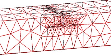
Table 2Un-cracked beam’s natural frequencies given for the first four vibration modes
Vibration mode | Natural frequencies (Hz) | |
The FE package | The Ritz’s approximation with 9 terms | |
1 | 63.37 | 63.26 |
2 | 395.72 | 396.09 |
3 | 1101.7 | 1107.47 |
4 | 2141.6 | 2165.7 |
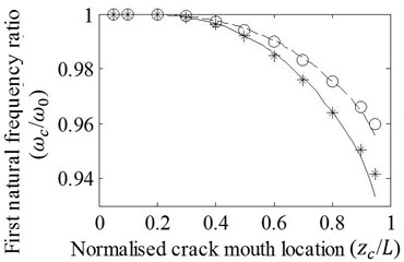
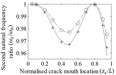
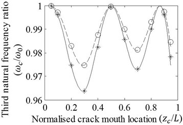
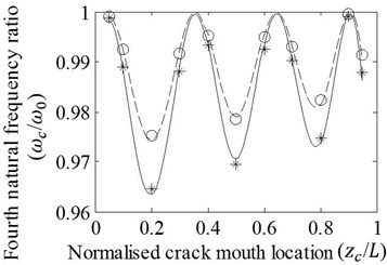
Case 1: T shaped cracks with varying locations for two axial progression lengths are covered. Good agreement between the first four natural frequency ratios of cracked/un-cracked beams attained by the FE analysis and the approach is shown in Fig. 4. When a crack is shifted along the beam, natural frequency ratios fluctuate due to the effect of modal bending moment varied through beam. It is also seen that natural frequency ratios representing similar fluctuations decrease with increasing length of axial crack progression. Results are shown through the normalized crack mouth locations of 0.05-0.95 due to the necessity of spacing for axial crack progression. Moreover, the FE analysis may have difficulty in calculation of accurate result as well as the Ritz’s approximation method when the crack is very close to the beam ends.
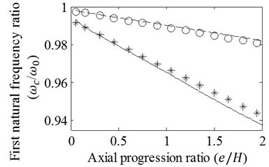
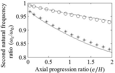
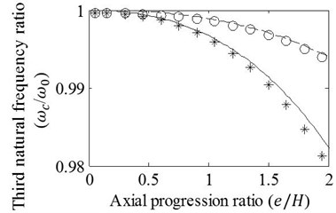
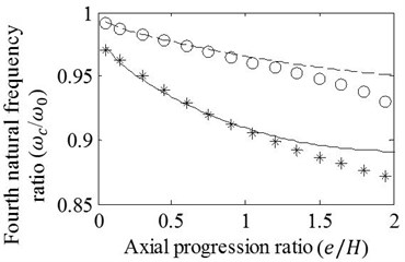
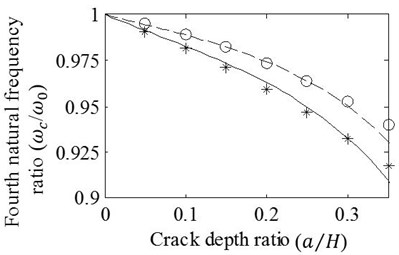
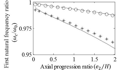
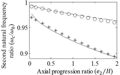
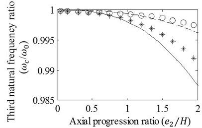
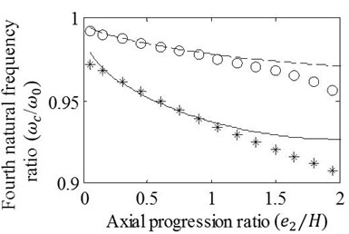
Case 2: T shaped cracks with varying axial progression lengths are modelled at the mid-span of the beam. Analyses are carried out for the crack depth ratios 0.15 and 0.30. Results obtained by the FE analysis and presented approach are shown in Fig. 5. It is obvious that natural frequency ratios decrease with increasing axial progression length and depth ratio of crack. It is also seen that differences between the results remain admissible for the first three vibration modes even if the ratio of axial crack progression, , is extended to very large values as 2. As one may expect, the accuracy of the approximation reduces with increasing vibration mode. Therefore, results of the approximation given as the ratios of the fourth mode natural frequencies seems not tolerable for . In other respects, Fig. 5(a) shows that axial crack progression results in almost linear alteration of the first natural frequency ratio that is reasoned by linear bending moment variation of the first vibration mode. When the natural frequency ratios of higher vibration modes are reflected, curvilinear changes are observed due to higher order bending moment variation that invites the energy release fluctuation varying with the location of crack tip. Since the mid-span crack is very close to the node point where the location has no energy release for the third vibration mode, Fig. 5(c) shows minor natural frequency drops whose rate slightly rises with increasing ratio of axial progression. On the contrary of Fig. 5(c), drop rate of natural frequencies decreases in Figs. 5(b), (d) because of the fact that the crack tips move away from the location of crack mouth where it has close proximity to the location of maximum bending moment for second and fourth vibration modes.
Fig. 4Effects of variation in zc/L on the a) first, b) second, c) third, and d) fourth natural frequency ratios of cracked/un-cracked beams. Ratios obtained by the FE analysis (o,*) and present method (—,– –) are plotted under the conditions: a/H=0.2, e1=e2=e, e/H=0.2 (o,– –) and e/H=0.4 (*,—)
a)
b)
c)
d)
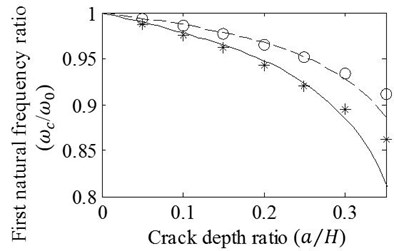
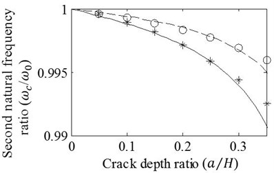
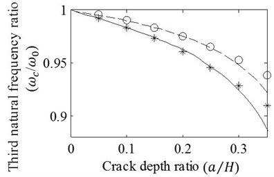
Case 3: Depth variation effects of T shaped cracks are inspected with axial progression ratios, 0.5 and 1. The cracks are modelled at the normalized location of 0.75. The first four modal frequency ratios obtained by the FE analysis and the method presented are shown in Fig. 6. It is observed that good agreement is achieved through , and nearly achieved up to even though the axial progression ratio reaches to significant level of 1. The figure also demonstrates that crack depth increments characterize the changes of natural frequency ratios as decaying curvilinear for all vibration modes.
Case 4: L shaped cracks located at the mid-span of the beam are modelled for inspecting the vibrational effects of varying axial progression length. The cracks with the depth ratios and are propagated to fixed side of cantilever beam.
Fig. 7 illustrates that when the depth ratio is 0.15, there exist allowable differences between the results of the approximation and the FE analysis even if the axial progression ratios, , reach to 2 for the first three vibration modes and 1.5 for the fourth mode. However, degree of matching between the results slightly decreases when the crack axially progresses with the depth ratio, 0.3. Discrepancies between the results become clear especially for the third and fourth natural frequency ratios obtained on condition of . The cracks analyzed in this case have the axial progressions that are one sided form of the cracks considered in case 2. Thus, of course the graphics seen in Fig. 7 resembles the graphics given in Fig. 5 except for the differences in amounts of natural frequency drops.
Fig. 5Effects of variation in e/H on the a) first, b) second, c) third, and d) fourth natural frequency ratios of mid-span cracked / un-cracked beams. Ratios obtained by the FE analysis (o,*) and present method (—,– –) are plotted under the conditions: e1=e2=e, a/H=0.15 (o,– –) and a/H=0.3 (*,—)
a)
b)
c)
d)
Fig. 6Effects of variation in a/H on the a) first, b) second, c) third, and d) fourth natural frequency ratios of cracked/un-cracked beams. Ratios obtained by the FE analysis (o,*) and present method (—,– –) are plotted under the conditions: zc/L=0.75, e1=e2=e, e/H=0.5 (o,– –) and e/H=1 (*,—)
a)
b)
c)
d)
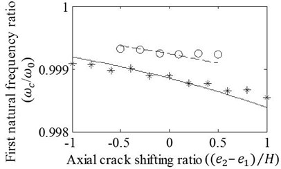
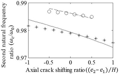
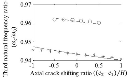
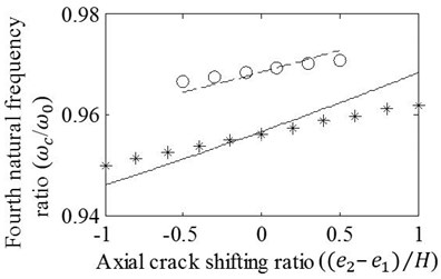
Case 5: Asymmetrical progression effects of the axial crack shifted around the crack mouth location are inspected by using the ratios of total axial progression fixed to 0.5 and 1. Fig. 8 illustrates resulting natural frequency ratios that linearly vary with shifting of axial crack. It is seen that the agreement of results obtained by the FE analysis and the approach slightly decreases as the T shaped crack transformed into L shaped. However, minor disparities between the results, which are particularly recognized for the beam with L shaped crack, is accepted to be still satisfactory. Another remarkable fact seen in the figure is the variation of the natural frequency ratio that shows either decreasing or increasing trends changing with vibration mode while the axial cracking is moved toward fixed side of the beam. This variation is in agreement with Fig. 4 that exhibits the slope of modal frequency fluctuation in the vicinity of normalized crack location, 0.25. In other respects, negligible differences may seem significant in Fig. 8 because of the depiction in narrow band that reveals the trend of natural frequency ratios changing slightly. It is seen that even the FE package cannot distinguish the neighbor cases of axial crack shifting that cause very small natural frequency drop changes illustrated in narrow band. Accordingly, it can be concluded that presented model is usable for the beams with either T or L shaped crack although it is more appropriate for the beam with T shaped crack.
Fig. 7Effects of variation in e2/H on the a) first, b) second, c) third, and d) fourth natural frequency ratios of mid-span cracked/un-cracked beams. The ratios obtained by the FE analysis (o,*) and present method (—,– –) are plotted under the conditions: e1=0, a/H=0.15 (o,– –) and a/H=0.3 (*,—)
a)
b)
c)
d)
4. Conclusions
In this paper, theoretical contributions are introduced for identifying the flexural vibration of the beam with T shaped crack progressed symmetrically/asymmetrically or L shaped crack. To the best knowledge of the author, this can be the first paper presenting the vibration analyses of the beam including these types of cracks. The theory presented is numerically verified using the FE analysis that models the cantilever beam with several crack scenarios. Vibrational effects of T shaped cracks are inspected in case studies by changing the axial crack progression, crack mouth location, and crack depth ratio. L shaped cracks and asymmetrical axial progression of cracks are also studied in other cases.
The energy release formulations are given in fracture mechanics for the stressed element with T shaped crack progressed through short span of axial direction. These formulations have been rearranged to find the energy consumed by a breathing crack in bending beam. Proposed theoretical adjustments make available the identification of consumed energy distribution for bending beam with T or L shaped cracks axially progressed through much longer span. As a result of the characterization of balanced energy distribution, the natural frequencies of beams with the cracks considered are easily obtained by performing the Ritz’s method with 9 terms.
Fig. 8Effects of variation in (e2-e1)/H on the a) first, b) second, c) third, and d) fourth frequency ratios of cracked/un-cracked beams. Ratios obtained by the FE analysis (o,*) and present method (—,– –) are plotted under conditions: zc/L=0.25, (e1+e2)/H=0.5 (o,– –) and (e1+e2)/H=1 (*,—)
a)
b)
c)
d)
Results show that the theory presented and the solution approximation achieve to obtain vibration characteristics of the beam with the cracks considered. Theoretical adjustments largely extend the accuracy limits given for the axial progressions and depths of the cracks. A significant advantage of the method presented is to find solution in acceptable period of time that does not change even if the crack has long axial progression. However, duration of the solution raises with increasing length of the crack modelled in the FE package. Consequently, it is possible to foresee that good results for long span of axial crack progression satisfy the researchers who pay attention to vibrational effects of the fractures in mechanical or structural elements. Results may also open up one’s horizon to analyze the vibration of layered composite beams with an edge crack progressed through layers. Finally, results form a basis to develop an inverse method for considered crack types since the natural frequencies obtained by experimental tests are frequently employed as inputs of crack identification techniques. Thus, results can be tested experimentally in future works on frequency based inverse techniques.
References
-
Dimarogonas A. D. Vibration of cracked structures: a state of the art review. Engineering Fracture Mechanics, Vol. 55, Issue 5, 1996, p. 831-857.
-
Jassim Z. A., Ali N. N., Mustapha F., Abdul Jalil N. A. A review on the vibration analysis for a damage occurrence of a cantilever beam. Engineering Failure Analysis, Vol. 31, 2013, p. 442-461.
-
Ostachowicz W. M., Krawczuk M. Analysis of the effect of cracks on the natural frequencies of a cantilever beam. Journal of Sound and Vibration, Vol. 150, Issue 2, 1991, p. 191-201.
-
Dado M. H. A comprehensive crack identification algorithm for beam under different end conditions. Applied Acoustics, Vol. 51, Issue 4, 1997, p. 381-398.
-
Khiem N. T., Lien T. V. A simplified method for natural frequency analysis of a multiple cracked beam. Journal of Sound and Vibration, Vol. 245, Issue 4, 2001, p. 737-751.
-
Lin H. P. Direct and inverse methods on free vibration analysis of simply supported beams with a crack. Engineering Structures, Vol. 26, 2004, p. 427-436.
-
Attar M. A transfer matrix method for free vibration analysis and crack identification of stepped beams with multiple edge cracks and different boundary conditions. International Journal of Mechanical Sciences, Vol. 57, Issue 1, 2012, p. 19-33.
-
Christides S., Barr A. D. S. One dimensional theory of cracked Bernoulli-Euler beams. International Journal of Mechanical Sciences, Vol. 26, 1984, p. 639-648.
-
Chondros T. G., Dimarogonas A. D., Yao J. Vibration of a beam with a breathing crack. Journal of Sound and Vibration, Vol. 239, Issue 1, 2001, p. 57-67.
-
Yang X. F., Swamidas A. S. J., Seshadri R. Crack identification in vibrating beams using the energy method. Journal of Sound and Vibration, Vol. 244, Issue 2, 2001, p. 339-357.
-
Mazanoglu K., Sabuncu M. Flexural vibration of non-uniform beams having double edge breathing cracks. Journal of Sound and Vibration, Vol. 329, Issue 20, 2010, p. 4181-4191.
-
Ishak S. I., Liu G. R., Lim S. P. Study on characterization of horizontal cracks in isotropic beams. Journal of Sound and Vibration, Vol. 238, Issue 4, 2000, p. 661-671.
-
Thalapil J., Maiti S. K. Detection of longitudinal cracks in long and short beams using changes in natural frequencies. International Journal of Mechanical Sciences, Vol. 83, Issue 1, 2014, p. 38-47.
-
Kıral B. G. Free vibration analysis of delaminated composite beams. Science and Engineering of Composite Materials, Vol. 16, Issue 3, 2009, p. 209-224.
-
Li D., Qing G. Free vibration analysis of composite laminates with delamination based on state space theory. Mechanics of Advanced Materials and Structures, Vol. 21, Issue 5, 2014, p. 402-411.
-
Mazanoglu K., Sabuncu M. Vibration analysis of non-uniform beams having multiple edge cracks along the beam’s height. International Journal of Mechanical Sciences, Vol. 52, Issue 3, 2010, p. 515-522.
-
Nandwana B. P., Maiti S. K. Modelling of vibration of beam in presence of inclined edge or internal crack for its possible detection based on frequency measurements. Engineer Fracture Mechanics, Vol. 58, Issue 3, 1997, p. 193-205.
-
Eisenberger M. Exact vibration frequencies and modes of beams with internal releases. International Journal of Structural Stability and Dynamics, Vol. 2, Issue 1, 2002, p. 63-75.
-
Tada H., Paris P. C., Irwin G. R. The Stress Analysis of Cracks Handbook, Third Edition. ASME, Newyork, 2000.
About this article

