Abstract
Due to the machining errors, alignment error, wear, tear and time varying stiffness of hypoid teeth, the vibration of hypoid gears is inevitably produced in the course of working, and its vibration and noise is the main sources of vibration and noise in the automobile transmission. Study on nonlinear vibration and noise of the hypoid gear pair, and investigating on reducing its vibration and noise are of great significance. Firstly, a simplified nonlinear vibration model of the hypoid gears of main reducer, with considering the time-varying teeth stiffness and teeth surface friction damping, was established. Then, a numerical simulation method was employed to simulate different gear backlash effects on the hypoid gear vibration behaviors caused by the gear worn, and effects on the gear non-linear vibration from different work speeds of gear and different loading torques were investigated. In order to help to explain the non-linear vibration phenomenon of the hypoid gears, the 2-D phase plane diagram and the 3-D trajectory were employed. Lastly, the bench test was carried out to verify the simulation results on vibration of hypoid gears with backlash.
1. Introduction
The hypoid gear is usually used in the main reducer of automobile driving axle assembly. Due to the machining errors, alignment error, wear, tear and time varying stiffness of hypoid teeth, the vibration of hypoid gears is inevitably produced in the course of working. The dynamic characteristics of the hypoid gear directly affects the smooth running and reliability of driving axle, and its dynamic characteristics research has attracted the attentions of a lot of scholars. Many achievements on linear vibration investigations and dynamic tests have been obtained. The hypoid gear pair transmission system consists of many nonlinear factors, such as time-varying mesh stiffness, transmission error, the tooth backlash, etc., which have great influences on the pair meshing stability and work reliability. Dequan Jin and Huibin Li [1, 2], Jianping Gao [3], Zongde Fang, Jianjun Wang, Runfang Li [4-6], Kahraman A. [7-15] et al. have performed a lot of theoretical and experimental studies on vibration problems from the teeth stiffness, gear backlash and eccentric quality. Their researches showed that the tooth clearances altered fault vibration frequencies, and with the increase of the tooth clearances, the sub-harmonic and ultra-harmonic responses would be generated. Mohammadpour M., et al. [16, 17] presented a combined multi-body dynamics and lubricated contact mechanics model of vehicular differential hypoid gear pairs, demonstrating the transient nature of transmission efficiency and noise, vibration and harshness performance under various driving conditions. The coefficient of friction was obtained using an analytical approach for non-Newtonian lubricant shear and supplemented by boundary interactions for thin films. Additionally, road data and aerodynamic effects are used in the form of resisting torque applied to the output side of the gear pair. Sinusoidal engine torque variation is also included to represent engine order torsional input resident on the pinion gear. Zhang Xiaofan, et al. [18-20] studied the gear transmission error, temporal and spectral characteristics of the angular acceleration with conditions of advancing, retreating or hang gap using dynamics simulation, as well as the analysis of the acceleration, and noise under different load and speed. The results show that the meshing noise and the contact pressure of the cycloid hypoid gears are smaller, and the meshing performance is optimal in driving forward state. However, the dynamic performance is poor at hand gap state. The data from these studies provide some design basis of the cycloid hypoid gears.
In this paper, a simplified nonlinear vibration model of the hypoid gears of main reducer, with considering the time-varying-teeth stiffness and teeth surface friction damping, will be established. Then, a numerical simulation method, namely the classical Runge-Kutta method was employed to calculate different gear backlash effects on the hypoid gear vibration behaviors caused by the gear worn, and effects on the gear non-linear vibration from different work speeds of gear and different loading torques will also be investigated. In order to help to explain the non-linear vibration phenomenon of the hypoid gears, the 2-D phase plane diagram and the 3-D trajectory were employed. Lastly, the bench test was carried out to verify the simulation results on vibration of hypoid gears with backlash.
2. Nonlinear vibration model for hypoid gear pair
Shown as Fig. 1 (a) and Fig. 1(b), a hypoid gear pair where the small gear is a driving gear, the big gear is the driven gear, and their nonlinear vibration mechanics model is shown as Fig. 1(c). Suppose the angular displacement, angular velocity, angular acceleration and rotating angular velocity of the driving gear’s torsional vibration are , , and respectively, and the angular displacement, angular velocity, angular acceleration and rotating angular velocity of the driven gear’s torsional vibration are , , and respectively. Then, ( is transmission ratio). In Fig. 1(c), – gear meshing stiffness, – gear damping coefficient, – gear backlash, – eccentricity, – gear composite error, – moment of inertia of driving gear, – moment of inertia of driven gear.
Fig. 1A nonlinear vibration model for a hypoid gear pair
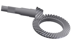
a) 3-D model of a hypoid gear pair
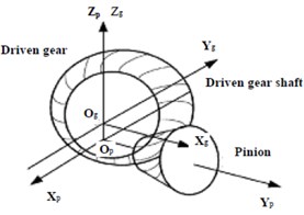
b) Geometric model
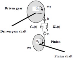
c) Vibration model
3. Nonlinear vibration equations of hypoid gear pair
According to the analysis of force of single stage hypoid gear system with two degrees of freedom, the gear vibration differential equations can be driven:
where relative vibration displacement of a pair of hypoid gears , and relative vibration velocity of a pair of hypoid gears . The derivative of the comprehensive gear errors with time is . The meshing radius of driving gear and driven gear are and respectively. In above equations, and are meshing point position vectors, and are normal unit vectors at meshing points, and are unit vectors along driving gear shaft and driven gear shaft respectively.
Obviously, due to the coefficients of , and related to time-varying stiffness and nonlinear function , Eq. (1) are nonlinear time-varying equations.
4. Numerical solutions for nonlinear vibration equations
If only considering gear backlash, then the Eq. (1) can be simplified as following:
As Eq. (2) are nonlinear time-varying, their theoretical solutions are difficult to be obtained and the numerical solutions are employed. For the convenience of calculation, the Eq. (2) are transformed into the state space, and the Eq. (2) are expressed as:
Then the original equations can be expressed as:
Numerical solutions of the Eq. (4) was obtained by using four orders of the classical Runge-Kutta method or four orders of Runge-Kutta-Gill method, and the vibration response of the hypoid gear pair can be obtained. Table 1 is the parameters of hypoid gear pair for calculation.
Table 1The main parameters of hypoid gear pair for calculation
Parameters | Values |
Shaft angle | 90° |
Big endian modulus | 3.953 mm |
Number of teeth | 9, 43 |
Offset distance | 30.000 mm |
Pitch circle radius | 20.823 mm, 72.382 mm |
Rated Torque | 284 Nm, 679 Nm |
Teeth width | 31.99 mm, 26.00 mm |
Equivalent mass of gear | 0.293 kg, 1.216 kg |
Moment of inertia | 0.0005 kg∙m2, 0.0125 kg∙m2 |
Rotating speed of driving gear | 1311-3686 rpm, corresponding to 30 km/h to 84 km/h of automobile’s driving velocity |
Backlash | 0.01-1.00 mm |
5. Simulation results
When digital simulations are performed by using Eq. (4), different combinations of backlash, gear rotating speed, torque (shown in Fig. 2 and Fig. 3) and teeth error of the gear pair are considered, and the simulation results are shown in Fig. 4 to Fig. 15.
Fig. 2Input torque of driving gear
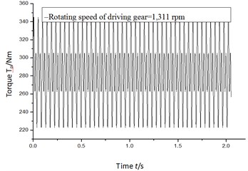
Fig. 3Load torque of driven gear
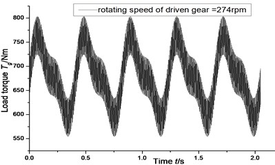
Fig. 4Vibration trajectory of a pair of hypoid gears (n= 1,311 rpm, Tp= 284 Nm, b= 0.01 mm)
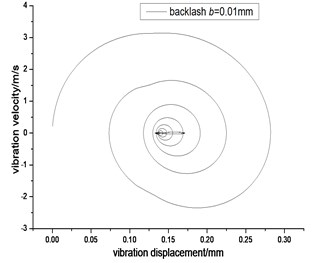
a) 2-D phase plane diagram
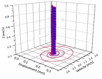
b) 3-D trajectory
Fig. 5Relative vibration velocity of a pair of hypoid gears (n= 1,311 rpm, Tp= 284 Nm, b= 0.01 mm)
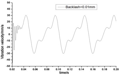
a) Response in time domain
b) Response in frequency domain
Fig. 6Vibration trajectory of a pair of hypoid gears (n= 1,311 rpm, Tp= 284 Nm, b= 0.1 mm)
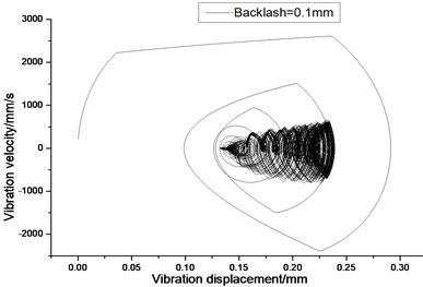
a) 2-D phase plane diagram
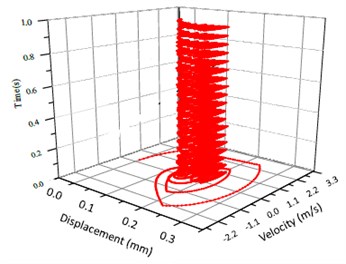
b) 3-D trajectory
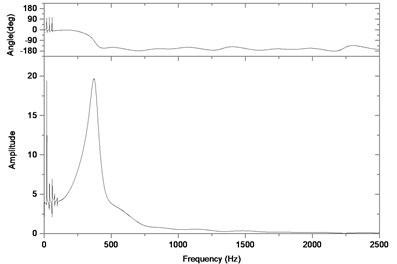
Fig. 7Relative vibration velocity of a pair of hypoid gears (n= 1,311 rpm, Tp= 284 Nm, b= 0.1 mm)
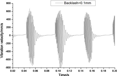
a) Response in time domain
b) Response in frequency domain
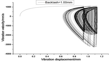
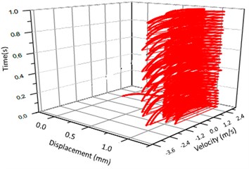
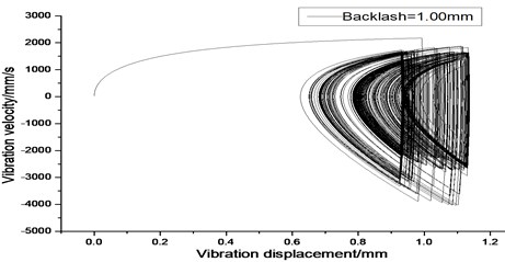
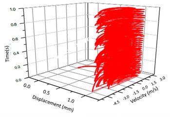
Fig. 8Vibration trajectory of a pair of hypoid gears (n= 1,311 rpm, Tp= 284 Nm, b= 1.0 mm)
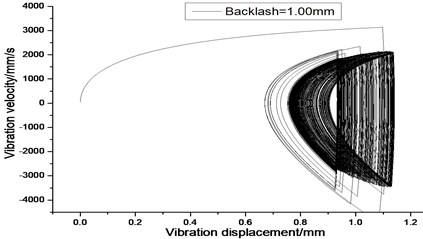
a) 2-D phase plane diagram
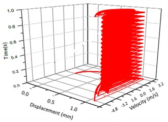
b) 3-D trajectory
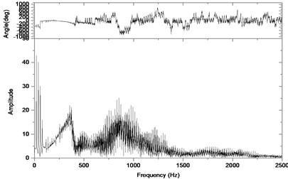
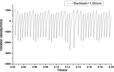
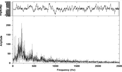
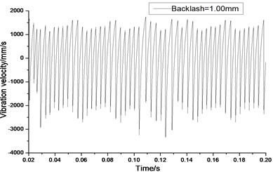
Fig. 9Relative vibration velocity of a pair of hypoid gears (n= 1,311 rpm, Tp= 284 Nm, b= 1.0 mm)
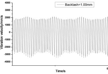
a) Response in time domain
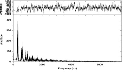
b) Response in frequency domain
Fig. 10Vibration trajectory of a pair of hypoid gears (n= 2,304 rpm, Tp= 76.5 Nm, b= 1.0 mm)
a) 2-D phase plane diagram
b) 3-D trajectory
Fig. 11Relative vibration velocity of a pair of hypoid gears (n= 2,304 rpm, Tp= 76.5 Nm, b= 1.0 mm)
a) Response in time domain
b) Response in frequency domain
Fig. 12Vibration trajectory of a pair of hypoid gears (n= 2,304 rpm, Tp= 153.0 Nm, b= 1.0 mm)
a) 2-D phase plane diagram
b) 3-D trajectory
Fig. 13Relative vibration velocity of a pair of hypoid gears (n= 2,304 rpm, Tp= 153 Nm, b= 1.0 mm)
a) Response in time domain
b) Response in frequency domain
Fig. 14Vibration trajectory of a pair of hypoid gears (n= 3,686 rpm, Tp= 96 Nm, b= 0.6 mm)
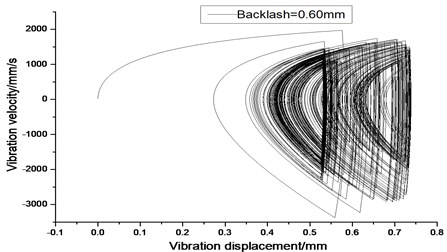
a) 2-D phase plane diagram
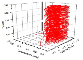
b) 3-D trajectory
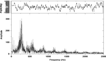
Fig. 15Relative vibration velocity of a pair of hypoid gears (n= 3,686 rpm, Tp= 96 Nm, b= 0.6 mm)
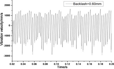
a) Response in time domain
b) Response in frequency domain
According to the above simulation results, we can find that when the gear tooth wear is small, 2-D vibration phase trace closes to an ellipse and 3-D trajectory of relative vibration of hypoid gear tends to a cylinder. While the gear pair is in the moderate wear, for example, backlash 0.1 mm, the tooth side clearance of gear tooth is larger, and the relative vibration velocity waveform changes a lot. At the same time, gear vibration velocity rises sharply, and there is the emergence of beat vibration. The 2-D phase traces oscillate among multiple horn type curves, and vibration bifurcation appears. Furthermore, the 3-D trajectory develops to form two parabolic, one large and other small.
When the gear tooth wears much severely, for example, backlash 1.0 mm, the relative displacement amplitude of gear teeth changes little and its vibration frequency spectrum characteristics also changes slightly, but the spectrum characteristics of vibration velocity changes significantly. Under such a situation, the beat vibration appears, phase trace oscillates among multiple horn type curves, and the vibration belongs to the bifurcation and chaos. Then the 3-D trajectory still develops to form two parabolic, one large and other small.
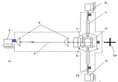
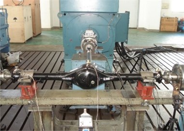
Fig. 16Bench test layout for vibration and noise measurement of driving axle: 1 – variable frequency driving motor; 2 – universal joint; 3 – driving shaft; 4 – main reducer; 5 – driving axle case; 6 – the differential; 7 – differential axle; 8 – loading motor; 9 – torque sensor; 10 – acoustical sensor; 11 – acceleration sensor
a)
b)
6. Bench test on vibration and noise of driving axle with hypoid gears
Fig. 16 is Bench test layout for vibration measurement of driving axle with a hypoid gear pair. The bench experiment is to verify the above simulation results. As the main frequencies of vibration of driving axle are below 2,000 Hz, so the sampling rate was set as 4,000 Hz. Three acceleration signals, three torque signals, four acoustical signals, and one tachometer signal were sampled synchronously. The data acquisition system was DASP 306. The vibration acceleration sensor model is BZ1113, its frequency response range of 0.2 Hz-5 kHz, and its sensitivity of 10 PC/ms-2 (at 1,000 Hz). The microphone model is B&K4197, its frequency response range of 20 Hz-40 kHz, and its sensitivity of 12.5 mv/Pa (at 250 Hz).
Fig. 17Trend of vibration and noise near main reducer with meshing cycles
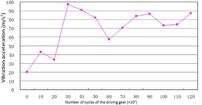
a) Trend of vibration
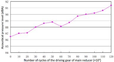
b) Trend of noise
Fig. 18Vibration near the main reducer at starting time (n= 2,304 rpm, Tp= 153.0 Nm, b= 0.1 mm)
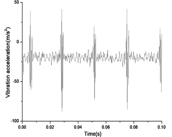
a) Response in time domain
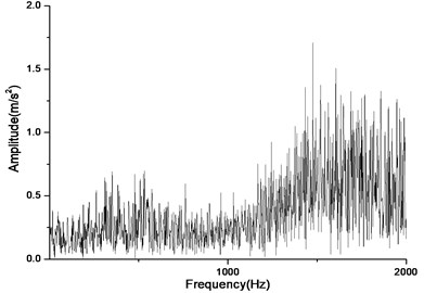
b) Response in frequency domain
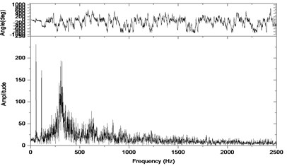
Fig. 19Vibration near the main reducer with wear and spot teeth fault (n= 2,304 rpm, Tp= 153.0 Nm, b= 1.0 mm)
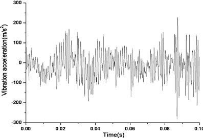
a) Response in time domain
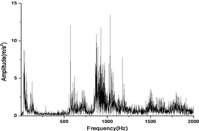
b) Response in frequency domain
According to Fig. 17(a) and Fig. 17(b), we can find out that the noise and vibration level increase with the development of wear and crack of gears and bearings. Due to the increment of teeth’s wear, the backlash between a pair of gears increase and the meshing impacts naturally are raised. By comparing Fig. 18 and Fig. 19, we can also find out that the main frequency components of vibration change with the development of wear and crack of gears and bearings. In the starting time of the experiment, as the pair of gears belongs to not a good product, the main frequency components of vibration near the main reducer consist of one time, twice, three and four times of gears’ meshing frequencies. But at moment of the fault for the driving axle, main frequency components of noise near the main reducer consist of twice, three times and four times of gears’ meshing frequencies. In addition to these frequencies, one and two times of rotating frequencies of driving shaft. Fig. 20 is the pair of hypoid gears with wear and spot teeth fault.
Shown as Fig. 17 to Fig. 20, the bench test verified the simulation results. The experimental results show that not only do the vibration level and noise level change with the wear of gears and bearings, but also with the development of the wear of gear and bearings, do the frequency components of vibration and noise change more with the number of cycles. These reasons come from the nonlinear vibration of gears caused by backlash and time-varying stiffness of the meshing teeth. The above experiment results also show that the simulation results could predict the fault of driving axle correctly in the different stages of services.
Fig. 20A pair of hypoid gears with wear and spot teeth fault
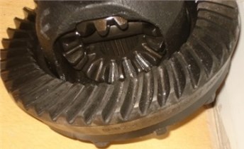
a) Driven gear
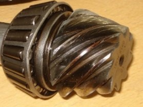
b) Pinion
7. Conclusion
1) In this paper a simplified dynamic model of the hypoid gears of main reducer, with considering the time-varying-teeth stiffness, was established, and on the basis of the work, a non-linear vibration equation of the hypoid gear with the backlash was derived. A numerical simulation method was employed to calculate different gear backlash effects on the hypoid gear vibration behaviors caused by the gear worn, and study effects on the gear non-linear vibration from different work speeds of gear and different loading torques.
2) Under situation of the gear working speed and load unchanged, the gear’s wear has effects on the vibration displacement, vibration velocity and vibration acceleration. When the gear wear is intensified, then the tooth backlash increases. This reduces tooth stiffness and results in the change of vibration displacement, vibration velocity and vibration acceleration amplitude. As a result, the beat vibration appears, phase trace oscillates among multiple horn type curves, and the vibration belongs to the bifurcation and chaos. Furthermore, the 3-D trajectory develops to form two parabolic, one large and other small.
3) The nonlinear vibration simulation with gear’s backlash shows that the changes of the working speed have great influence on the vibration velocity of gear at those fault frequencies. The higher working speeds, the more obvious vibration velocity amplitude at fault vibration frequencies.
4) The nonlinear vibration simulation with gear’s backlash also shows that the changes of working load amplitude have small influence on both gear vibration frequencies and the amplitudes of the vibration velocity.
5) In order to study deeply the non-linear vibration phenomenon of the hypoid gears with backlash and wear, the 2-D phase plane diagram and the 3-D trajectory could be employed. And the simulation results indicate that when the pair of gears of main reducer produce wear and the backlash between the pair of gears belongs to moderate degree and above, the 3-D trajectory develops to form two parabolic, one large and other small.
6) The presented results could be used for damage detection in hypoid gears in most working situations and the on-line driving axle’s hypoid gear damage diagnosis system has been developed for the product line of an automobile corporation. But if the better effects for damage diagnosis in hypoid gears are wanted, then the other diagnosis techniques such as Kurtosis coefficient and wavelet packet coefficients need to be combined.
References
-
Jin D. Q., Li H. B., Gao H. C. Study on vibration of hypoid gear with backlash. Proceeding of AMEII, 2015, p. 800-804.
-
Li H. B. Reports on Optimization Analysis of the Commercial Vehicle Driving System for Chongqing Changan Automobile Company. Beijing Institute of Technology, 2012, (in Chinese).
-
Gao J. P., Fang Z. D., Yang H. B. Dynamic analysis of spur gear pairs with time-varying mesh stiffness and clearance non-linearity. Acta Aeronautica et Astronautica Sinica, Vol. 20, Issue 5, 1999, p. 440-443, (in Chinese).
-
Li R. F., Wang J. J. Gear System Dynamics. Science Publishing Company, Beijing, 1997, (in Chinese).
-
Ozguven H. N., Houser D. R. Mathematical models used in gear dynamics-a review. Journal of Sound and Vibration, Vol. 121, Issue 3, 1988, p. 383-411.
-
Wang S. M., Shen Y. W., Dong H. J. Non-linear dynamical characteristics of a spiral bevel gear system with backlash and time-varying stiffness. Chinese Journal of Mechanical Engineering, Vol. 39, 2003, p. 28-32.
-
Kahraman A. Dynamic analysis of a multi-mesh helical gear train. ASME Journal of Mechanical Design, Vol. 116, Issue 3, 1994, p. 706-712.
-
Kahraman A., Singh R. Non-linear dynamics of a geared rotor-bearing system with multiple clearance. Journal of Sound and Vibration, Vol. 113, Issue 3, 1991, p. 469-506.
-
Kahraman A., Blankenship G. W. Gear dynamics experiments. Part 3: effect of involute tip relief. American Society of Mechanical Engineers, Vol. 88, 1996, p. 389-396.
-
Kahraman A., Blankenship G. W. Effect of involute contact ratio on spur gear dynamics. ASME Journal of Mechanical Design, Vol. 121, Issue 1, 1999, p. 112-118.
-
Yang D. C. H., Lin J. Y. Herztian damping, tooth friction and bending elasticity in gear impact dynamics. ASME Journal of Mechanisms Transmissions and Automations in Design, Vol. 191, Issue 2, 1987, p. 189-196.
-
Blankenship G. W., Singh R. A new gear mesh interface dynamic model to predict multi-dimensional force coupling and excitation. Mechanism and Machine Theory, Vol. 30, Issue 1, 1995, p. 43-57.
-
Blankenship G. W., Singh R. Dynamic force transmissibility in helical gear pairs. Mechanism and Machine Theory, Vol. 30, Issue 3, 1995, p. 323-339.
-
Raghothama A., Narayanan S. Bifurcation and chaos in geared rotor bearing system by incremental harmonic balance method. Journal of Sound and Vibration, Vol. 121, Issue 3, 1999, p. 469-492.
-
Seyranian A. P., Solem F., Pedersen P. Multi-parameter linear periodic systems: sensitivity analysis and applications. Journal of Sound and Vibration, Vol. 122, Issue 1, 2000, p. 89-111.
-
Mohammadpour M., Theodossiades S., Rahnejat H., Kelly P. Transmission efficiency and noise, vibration and harshness refinement of differential hypoid gear pairs. Proceedings of the Institution of Mechanical Engineers, Part K (Journal of Multi-Body Dynamics), Vol. 228, Issue 1, 2014, p. 19-33.
-
Mohammadpour M., Theodossiades S., Rahnejat H. Tribo-dynamics of differential hypoid gears. Proceedings of the International Design Engineering Technical Conferences and Computers and Information in Engineering Conference, Vol. 5, 2013.
-
Yan H. Z., Liu M., Wang Y. Dynamic meshing performance of cycloid hypoid gear. Journal of Central South University (Science and Technology), Vol. 44, Issue 10, 2013, p. 4026-4032.
-
Karagiannis I., Theodossiades S. Dynamic analysis of automotive hypoid gears. Proceedings of the International Design Engineering Technical Conferences and Computers and Information in Engineering Conference, Vol. 7, Issue A, 2013.
-
Zhang X. F., Rao D. J., Zhao J. T. Vibration analysis of micro-vehicle main reducer based on ADAMS. Journal of Hefei University of Technology (Natural Science), Vol. 36, Issue 2, 2013, p. 129-170.
About this article

