Abstract
Herein, the pull-in instability of cantilever NEMS is studied considering the presence of dispersion forces and squeezed film damping. Recently developed consistent couple stress theory in combination with the Gurtin-Murdoch elasticity is employed to incorporate the coupled effects of size phenomena and surface energy. The governing equation was solved using Rayleigh-Ritz method. Effects of various parameters including surface layer, size dependency, dispersion forces and damping on the pull-in characteristics of the nano-actuator are discussed.
1. Introduction
Beam-type nano-actuators have become one of the common components in developing nano-electromechanical systems (NEMS). A typical NEMS actuator consists of a conductive beam suspended above a rigid conductive plate, by a dielectric spacer between the two components. By exceeding voltage beyond upper limit, the beam spontaneously collapses towards the plate and the pull-in instability occurs. In recent decade, comprehensive studies have been conducted on modeling the pull-in instability of micro-actuators [1-3]. With the decrease in device dimensions to the nano-scale the dispersion forces, i.e. Casimir and van der Waals (vdW) attractions, appear [4, 5]. At separations typically less than several tens of micrometers, the attraction between two surfaces could be described by the Casimir interaction [6]. Previous researchers studied the effect of the Casimir force on the instability of electromechanical systems [7-10]. However, when separation is less than several tens of nanometers, the Casimir force should be replaced by the vdW force. Some investigators have studied the effect of vdW attraction on the instability of electromechanical systems [11-13].
In addition, with dispersion forces, the surface layer characteristics might highly affect the behavior of nano-beams. Gurtin and Murdoch [14, 15] developed a continuum theory for modeling both residual surface stress and surface elasticity. This theory has been previously applied to investigate the effect of surface energy on the buckling [16], bending [17] and vibration [18] of nano-structures. In recent years, some researchers have investigated the influence of surface energy on the pull-in characteristics of electromechanical nano-bridge [19], nano-switches [20, 21], graphite NEMS [22] and micro-plates [23, 24].
Besides the surface energy, the effect of size i.e. microstructure-dependency of material characteristics at small scale might be necessary to be considered in modeling the nano-actuators. Experimental works [25-27] demonstrate that the size dependency is an inherent property of conductive metals. The classical continuum theory is not able to model the effect of microstructure. To overcome this shortcoming, the non-classical theories such as couple-stress theory [28], modified couple-stress theory [29], consistent couple stress theory (CCST) [30] etc. have been developed to consider the size effect. According to the modified couple stress theory the materials are in equilibrium if the applied forces, classical couples and moments of couples equal zero. The last premise is just an assumption and was not considered in the classical elasticity theories. Although the theory predicts stiffer models of micro/nanostructures, its correctness is still under question. In addition, this assumption results in a symmetric stress and couple-stress tensors that are not so reasonable due to the nature of the original theory especially for the couple-stress tensor. Since this additional consideration might not be acceptable, some researchers tried to find another reasonable solution. This could be achieved by using CCST [30, 31].
In this work, a modified beam model is developed for investigating the pull-in behavior of nano-actuators. The coupled effects of surface energy and microstructure are incorporated Analytical Rayleigh-Ritz method is employed to solve the nonlinear governing equation.
2. Theory
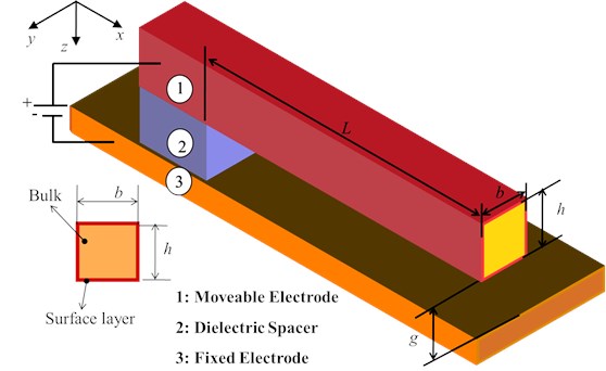
Fig. 1 shows the schematic representation of a nano-actuator. The NEMS actuator is modeled by a nano-beam of length , and a uniform cross-section of thickness and width .
Fig. 1Schematic representation of a cantilever nanoactuator
2.1. Fundamentals of consistent couple stress theory (CCST)
In the CCST, the equations of the isotropic materials are formulated as [30]:
where and represent the force-stress tensor (classical) and couple-stress tensors, respectively. In addition, and are the body force and the body couple per unit volume of the body, respectively. Here is the permutation tensor or Levi-Civita symbol.
The stress tensor is generally non-symmetric. Thus, it can be decomposed to the symmetric and skew-symmetric components as following:
where is the symmetric part and is the skew-symmetric part of the force-stress tensor.
In order to define the elements of Eqs. (1) and (2), the kinematic parameters should be utilized. The displacement gradient can be decomposed into two distinct parts:
where the strain tensor and the rotation tensor can explain as:
The rotation tensor is skew-symmetrical and a vector can be defined dual to it as:
The gradient of rotation tensor can be decomposed into two sub-tensors as:
where:
The corresponding dual vector of the skew-symmetric curvature tensor can be formulated as:
Substituting Eq. (6) in (8) one obtain:
The symmetrical part of the force-stress tensor in Eq. (2) is same as the force-stress tensor in classical elasticity and can be obtained as:
where and are the Lame’s constants. The couple-stress tensor is skew-symmetrical and a vector can be introduced dual to the tensor:
For the isotropic linear materials, the couple stress can be computed as [30]:
The parameter, , varies from one scale to another scale. Hadjesfandiari and Dargush [30] showed that the skew-symmetric component of the stress tensor can be obtained as:
Therefore, the strain energy density can be written as [31]:
2.2. Fundamentals of surface elasticity
According to the surface elasticity the strain energy in the surface layer () is [32]:
The governing equations for the surface layer of zero thickness can be explained as [32]:
where are the components of the traction vector on the surface, are the components of the surface curvature tensor, are the components of the outward unit normal to the surface () (with being the in-plane components of ), and are given by:
where and are the surface elastic constants, and is the residual surface stress and the out-of-plane components of the surface stress tensor are given by [15]:
2.3. Nonlinear constitutive equation
For a Euler-Bernoulli beam, the displacement field can be expressed as [33]:
where is the centerline deflection of the beam in the direction and , and are the displacement components in the , and directions, respectively.
2.3.1. Size dependent strain energy of the bulk
Substituting Eq. (20) in Eqs. (4)-(6) and (13) the nonzero components are obtained as:
By substituting Eq. (21) in Eq. (15) after some elaboration and integrating over the beam volume, the bending strain energy is obtained as the following:
2.3.2. Strain energy in the surface layer
By substituting Eq. (20) in Eqs. (17)-(19), one obtains:
where is the surface elastic modulus. By substituting Eq. (23) in Eq. (16) the surface energy conclude as:
For rectangular cross section we have:
2.3.3. Work of external forces
The work by the external forces can be obtained as:
The external force () is the summation of electrical and dispersion forces.
The electrostatic force per unit length of the nano-beam can be written as[21]:
where 8.85×10⁻¹² c2 N-1m-2 is the vacuum permittivity and is the permittivity of dielectric.
The Casimir force per unit length of beam can be obtained as [32]:
where 1.055×10⁻³⁴ Js is the reduced Planck’s constant and 2.998×10⁸ m/s is the light speed.
The vdW force per unit length of beam can be explained as [4]:
where is the Hamaker constant.
2.3.4. Kinetic energy and squeezed film damping
The kinetic energy of the beam can be expressed as:
The squeezed film damping of parallel plates per unit length can be defined as [34]:
where is viscosity coefficient. Therefore, the virtual work performed by damping effects can be expressed as:
2.4. Dimensionless energy of system
The total energy of system can be summarized as:
Now, by substituting Eqs. (27)-(29) in Eq. (33), considering and and some mathematical elaboration the dimensionless total energy can be explained as:
where the dimensionless parameters are identified as:
3. Solution methods
To solve the governing equation using Rayleigh-Ritz method the displacement is expressed as a combination of independent basis functions in the form of:
where the index refers to the number of modes included in the simulation.
We use the linear mode shapes (based on the classic theory) as basic functions:
where is the th root of characteristic equation of the cantilever beams in the classical theory. For minimize the total energy of the system we must have:
This leads to a system of time-dependent equations which can be solved numerically. Substituting Eqs. (34) and (36) into Eq. (38), assuming the orthogonality of and following some mathematical operations, a system of governing equations is found as:
where:
The Maple software is employed to numerically solve the system of equations.
4. Results and discussion
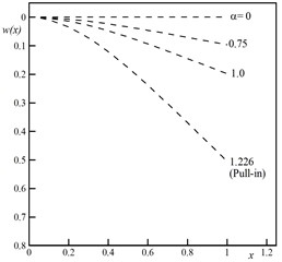
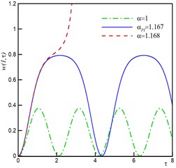
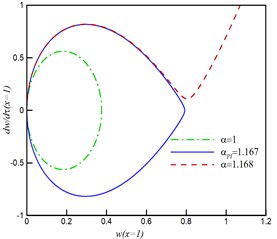
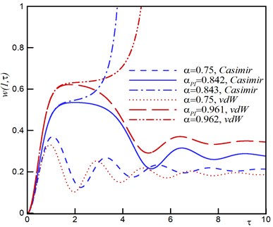
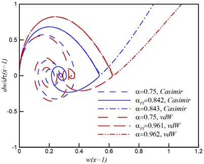
Fig. 2a shows the variation of static deflection of the actuator. The deflection of the actuator increases by increasing the applied voltage from zero to the pull-in value, . The time history and phase plane is shown in Fig. 2b and 2c. By increasing the voltage, the maximum amplitude of the tip deflection increases. If the applied voltage exceeds its critical value, , the pull-in occurs. The phase plane has two fixed points; the stable center point and the unstable saddle node.
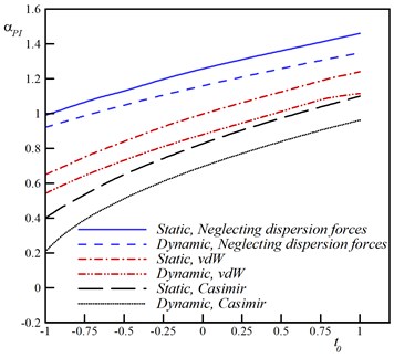
The impact of surface energy on the pull-in voltage is shown in Fig. 3a. As seen, by increasing the surface residual stress (), the pull-in voltage enhances. Surface stresses induce hardening or softening effect depends on its sign; when it is positive, surface effect increase the pull-in voltage and if it is negative, the surface effect reduces the pull-in voltage. The dynamic pull-in voltage is smaller than the static pull-in voltage due to inertia forces.
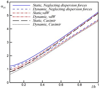
The influences of microstructure and dispersion forces on the pull-in voltage is shown in Fig. 3b. This figure reveals that the size parameter () results in increasing the pull-in voltage. While for lower values of the size parameter the presence of dispersion forces reduces the pull in voltage, for larger size parameter the effects of dispersion force are negligible.
Fig. 2Behavior of nano-actuator by neglecting size, surface and damping effect for different values of α from zero to pull-in voltage, a) Static deflection, b) Dynamic behavior, c) Phase plane
a)
b)
c)
Fig. 3Influence of small scale effect on the pull-in voltage
a) Surface effect
b) Size effect
Fig. 4 shows the influence of size parameter on the pull-in voltage when the positive and negative surface stresses, and , are considered as well as dispersion forces. This figure reveals that consideration of the size effect increases the pull-in voltage and has hardening effect. Fig. 4 reveals that the size effect always has hardening effect i.e. increases the pull-in voltage. For positive surface stress the surface effect increases the pull-in voltage (hardening effect) but for negative surface stress this effect decreases the pull-in voltage (softening effect).
Fig. 4Influence of size effect on pull-in voltage
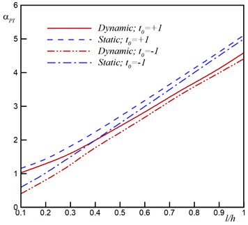
a) vdW regime
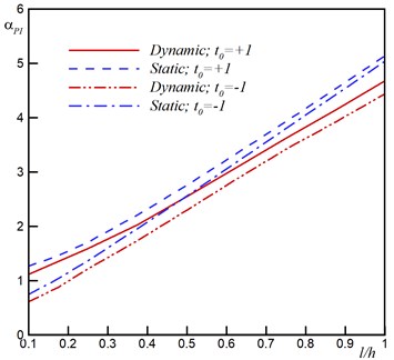
b) Casimir regime
Fig. 5Influence of damping on the dynamic behavior
a) Time history
b) Phase plane
To investigate the effect of damping, the time history and phase plane are plotted for 0.1, 0.05 0.5, 1, 0.2 and 0.5. As seen in Fig. 5, the system returns to the stable focus point. By considering the damping effect, the actuator will oscillate with decreasing amplitude and converges to equilibrium. For the pull-in voltage, the trajectories which are attracted to the stable focus point, diverge and the actuator becomes unstable.
4.1. Validation
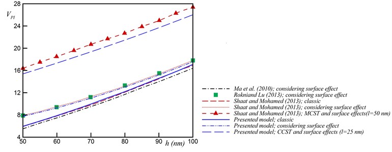
Consider an actuator with = 1 μm, = 5 h, = 50 nm and = 50–100 nm made of silver where the , , , , and values are 0.37, 25 nm 76 GPa, 0.89 N/m, 1.22 N/m, 3.5×10⁻¹⁹ J respectively. Fig. 6 represents the comparison between available results in the literature and those of our model. According to the present model, surface energy increases the pull-in voltage. However, the model by Ma et al. [20] shows reversed trends due to ignoring the surface stress in the boundary conditions. The results of the present model for classic state are in good agreement with Ma et al. [20]. By considering the surface effect the results of present model are close to those of Rokni and Lu [22] and Shaat and Mohamed [35].
Fig. 6Comparison of results from the present model with those from literatures
5. Conclusions
The coupled effects of surface energy and microstructure on pull-in behavior of the nano-actuators were studied. The obtained results revealed that the surface layer might significantly affect the pull-in of the actuators and cannot be ignored in theoretical model. For positive surface stress, the surface layer increases the pull-in voltage. However, if the surface stress be negative, the surface effect reduces the pull-in voltage. The size effect always increases the pull-in voltage, while the dispersion forces decreases the pull-in voltage.
References
-
Lin W. H., Zhao Y. P. Pull-in instability of micro-switch actuators: model review. International Journal of Nonlinear Sciences and Numerical Simulation, Vol. 9, Issue 2, 2008, p. 175-184.
-
Moghimi Zand M., Ahmadian M. T. Vibrational analysis of electrostatically actuated microstructures considering nonlinear effects. Communications in Nonlinear Science and Numerical Simulation, Vol. 14, Issue 4, 2009, p. 1664-1678.
-
Tajaddodianfar F., Pishkenari H. N., Yazdi M. R. H., Miandoab E. M. On the dynamics of bistable micro/nano resonators: Analytical solution and nonlinear behavior. Communications in Nonlinear Science and Numerical Simulation, Vol. 20, Issue 3, 2015, p. 1078-1089.
-
Soroush R., Koochi A., Kazemi A. S., Noghrehabadi A., Haddadpour H., Abadyan M. Investigating the effect of Casimir and van der Waals attractions on the electrostatic pull-in instability of nano-actuators. Physica Scripta, Vol. 82, Issue 4, 2010, p. 045801.
-
Batra R. C., Porfiri M., Spinello D. Effects of Casimir force on pull-in instability in micromembranes. EPL (Europhysics Letters), Vol. 77, Issue 2, 2007, p. 20010.
-
Gusso A., Delben G. J. Dispersion force for materials relevant for micro-and nanodevices fabrication. Journal of Physics D: Applied Physics, Vol. 41, Issue 17, 2008, p. 175405.
-
Batra R. C., Porfiri M., Spinello D. Reduced-order models for microelectromechanical rectangular and circular plates incorporating the Casimir force. International Journal of Solids and Structures, Vol. 45, 2008, p. 3558-3583.
-
Gusso A., Delben G. J. Influence of the Casimir force on the pull-in parameters of silicon based electrostatic torsional actuators. Sensors and Actuators A: Physical, Vol. 135, Issue 2, 2007, p. 792-800.
-
Lin W. H., Zhao Y. P. Nonlinear behavior for nanoscale electrostatic actuators with Casimir force. Chaos, Solitons and Fractals, Vol. 23, Issue 5, 2005, p. 1777-1785.
-
Koochi A., Kazemi A. S., Beni Y. T., Yekrangi A., Abadyan M. Theoretical study of the effect of Casimir attraction on the pull-in behavior of beam-type NEMS using modified Adomian method. Physica E: Low-dimensional Systems and Nanostructures, Vol. 43, Issue 2, 2010, p. 625-632.
-
Batra R. C., Porfiri M., Spinello D. Reduced-order models for microelectromechanical rectangular and circular plates incorporating the Casimir force. International Journal of Solids and Structures, Vol. 45, Issue 11, 2008, p. 3558-3583.
-
Dequesnes M., Rotkin S. V., Aluru N. R. Calculation of pull-in voltages for carbon-nanotube-based nanoelectromechanical switches. Nanotechnology, Vol. 13, Issue 1, 2002, p. 120-131.
-
Rotkin S. V. Analytical calculations for nanoscale electromechanical systems. Electrochemical Society Proceedings, Vol. 6, 2002, p. 90-97.
-
Gurtin M. E., Murdoch A. I. A continuum theory of elastic material surfaces. Archive for Rational Mechanics and Analysis, Vol. 57, Issue 4, 1975, p. 291-323.
-
Gurtin M. E., Murdoch A. I. Surface stress in solids. International Journal of Solids and Structures, Vol. 14, Issue 6, 1978, p. 431-440.
-
Wang G. F., Feng X. Q. Surface effects on buckling of nanowires under uniaxial compression. Applied Physics Letters, Vol. 94, Issue 14, 2009, p. 141913.
-
He J., Lilley C. M. Surface effect on the elastic behavior of static bending nanowires. Nano Letters, Vol. 8, Issue 7, 2008, p. 1798-1802.
-
Yan Z., Jiang L. Y. The vibrational and buckling behaviors of piezoelectric nanobeams with surface effects. Nanotechnology, Vol. 22, Issue 24, 2011, p. 245703.
-
Fu Y., Zhang J. Size-dependent pull-in phenomena in electrically actuated nanobeams incorporating surface energies. Applied Mathematical Modelling, Vol. 35, Issue 2, 2011, p. 941-951.
-
Ma J. B., Jiang L., Asokanthan S. F. Influence of surface effects on the pull-in instability of NEMS electrostatic switches. Nanotechnology, Vol. 21, Issue 50, 2010, p. 505708.
-
Koochi A., Kazemi A. S., Khandani F., Abadyan M. Influence of surface effects on size-dependent instability of nano-actuators in the presence of quantum vacuum fluctuations. Physica Scripta, Vol. 85, Issue 3, 2012, p. 035804.
-
Rokni H., Wei L. A continuum model for the static pull-in behavior of graphene nanoribbon electrostatic actuators with interlayer shear and surface energy effects. Journal of Applied Physics, Vol. 113, Issue 15, 2013, p. 153512.
-
Ansari R., Gholami R., Shojaei M. F., Sahmani S. Surface stress effect on the pull-in instability of circular nanoplates. Acta Astronautica, Vol. 102, 2014, p. 140-150.
-
Wang K. F., Wang B. L. Effect of surface energy on the non-linear postbuckling behavior of nanoplates. International Journal of Non-Linear Mechanics, Vol. 55, 2013, p. 19-24.
-
Fleck N. A., Muller G. M., Ashby M. F., Hutchinson J. W. Strain gradient plasticity: theory and experiment. Acta Metallurgica et Materialia, Vol. 42, Issue 2, 1994, p. 475-487.
-
Lam D. C. C., Yang F., Chong A. C. M., Wang J., Tong P. Experiments and theory in strain gradient elasticity. Journal of the Mechanics and Physics of Solids, Vol. 51, Issue 8, 2003, p. 1477-1508.
-
McFarland A. W., Colton J. S. Thermoplastic polymer microcantilever sensors fabricated via micromolding. Journal of Micromechanics and Microengineering, Vol. 15, Issue 5, 2005, p. 1060-1067.
-
Ejike U. B. The plane circular crack problem in the linearized couple-stress theory. International Journal of Engineering Science, Vol. 7, Issue 9, 1969, p. 947-961.
-
Yang F., Chong A. C. M., Lam D. C. C., Tong P. Couple stress based strain gradient theory for elasticity. International Journal of Solids and Structures, Vol. 39, Issue 10, 2002, p. 2731-2743.
-
Hadjesfandiari A. R., Dargush G. F. Couple stress theory for solids. International Journal of Solids and Structures, Vol. 48, Issue 18, 2011, p. 2496-2510.
-
Fakhrabadi M. M. S., Yang J. Comprehensive nonlinear electromechanical analysis of nanobeams under DC/AC voltages based on consistent couple-stress theory. Composite Structures, Vol. 132, 2015, p. 1206-1218.
-
Wang K. F., Wang B. L. Influence of surface energy on the non-linear pull-in instability of nano-switches. International Journal of Non-Linear Mechanics, Vol. 59, 2014, p. 69-75.
-
Dym C. L., Shames I. H. Solid Mechanics: A Variational Approach. Railway Publishing House, Beijing, China, 1984.
-
Krylov S. Lyapunov exponents as a criterion for the dynamic pull-in instability of electrostatically actuated microstructures. International Journal of Non-Linear Mechanics, Vol. 42, Issue 4, 2007, p. 626-642.
-
Shaat M., Mohamed S. A. Nonlinear-electrostatic analysis of micro-actuated beams based on couple stress and surface elasticity theories. International Journal of Mechanical Sciences, Vol. 84, 2014, p. 208-217.
Cited by
About this article

