Abstract
An analysis of existing air independent propulsion system solutions shows that fuel cells have the potential to achieve the greatest energy efficiency and silencing actions resulting from direct conversion of energy during a chemical reaction without moving parts. This paper describes research intended to identify noise generated by a fuel cell demonstrator and the first phase of work related to its silencing. During these investigations main noise sources were determined, while sound propagation and sound insulation of the fuel cell enclosure were performed in accordance with the civilian and military standardization guidelines.
1. Introduction
In recent years an increasingly important trend for NATO forces emerged – to drive from the sea on land, using the expeditionary force and arms to the so-called deep strokes. That translates into future growth of military importance of coasts. Currently, the most likely tasks for submarines include: support activities in coastal waters, technical observation of shipping lanes and waters vulnerable to terrorist attacks (ISR scenarios), communications nodes in the network-centric command systems and securing Special Forces operations. In all these operations in the first place put at the necessity to use on Air Independent Propulsion (AIP) allows as long as possible and underwater silent movement. Currently three different technical solutions are applied to address the issue in question: Stirling engines, MESMA system and PEM fuel cells. Analysis of existing AIP system solutions demonstrates that fuel cells have potential to achieve the greatest energy efficiency and silencing actions resulting from direct conversion of energy during a chemical reaction without moving parts [1, 2].
The Polish Naval Academy (PNA) made hardware technology demonstrator backup power supply for submarine using a hydrogen fuel cell, and the Polish Ministry of Defence commissioned from PNA a project No. DNiSW/U/9/BN/1.16/2008/847 regarding such technology. In the framework of that project, based on data obtained from previous simulation studies designed, built and tested the basic performance characteristics demonstrator proton exchange membrane (PEM) fuel cell. It electromechanical parameters meet the assumptions regarding backup power source Kobben type submarine used in the Polish Navy. Realized physical demonstrator allows to become familiar with the advantages and limitations of operating the most modern technologies currently power supply as well as to identify sources of work-related distribution systems, reagents and flow of water to ensure proper operation of the stack, as well as the development of methods to minimize them.
The configuration of fuel cell demonstrator allows further research in aspect of generating noise. The assumption that fuel cell is backup power used in emergency of submarine resulted in a lack of requirements for level and characteristics noise. The design and construction of warships and submarines in particular is subordinated to the low detection task, so each device mounted on a ship must also satisfy conditions of low observable in this case the maximum noise reduction [3]. The research described in this article is intended to identify noise generated by the fuel cell demonstrator (also in relation to the existing civilian and military standardization documents) and are the first phase of work related to its silencing [4].
2. Measurement methods and equipment
The measurement of vibration and analysis were performed in accordance with standard ISO 10816-1 [6] concerning evaluation of machine vibration by measurements on non-rotating parts and PN-EN 60994 [7]. In all cases time courses of acceleration (in frequency band 0.5 to 3000 Hz) has been measured at body of FC PEM 6 kW and at two significant sources of vibration: a hydrogen recirculation pump, a cooling pump (see Fig. 1).
The acoustic measurements to determine the sound propagation and sound insulation of the fuel cell enclosure were performed in accordance with the guidelines contained in [8-17].
In all cases time courses of sound pressure (in frequency band 2 Hz to 20 kHz) has beed measured at two points according [9] (see Fig. 1 and Fig. 2). Measuring microphones has been placed at a distance of 0.5 m from the enclosure of FC PEM 6 kW at a height of 0.7 meters above ground level.
Fig. 1View of the device under test with location of microphones and 3-axis acceleration sensors
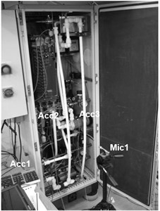
a) Microphone (Mic1); accelerometers (Acc1-Acc3)
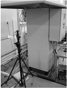
b) Microphone (Mic2)
Fig. 2View of the mounting of 3-axis acceleration sensors with directions of vibration measurements on
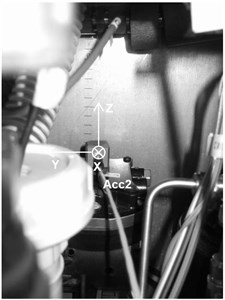
a) The hydrogen recirculation pump
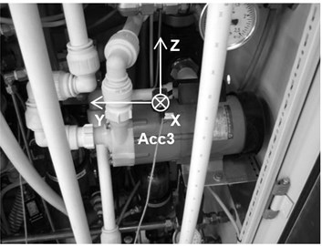
b) The cooling pump
The measurements were carried out parallely for both acoustic and vibration channels during 4 states of working: start-up, no-load operation, load operation, withdrawal in 2 variants – with a closed and an open housing of the fuel cell (Fig. 1).
The measurements were performed using:
• 16 channels LMS Scadas Mobile System with 2 input modules: VM8-E, V8-E;
• LMS Test.Xpress 7A Siemens Software;
• 2 pieces ½” random – incidence microphones with preamplifiers PCB Model No. 378B20;
• 3 pieces 3-axis accelerometers Model PCB ICP No. 356B18.
Measuring precision has been ensured by reference sound source type 4231 Brüel & Kjær with a level of 114 dB at 1 kHz and by reference hand-held accelerometer calibrator type 4294 Brüel & Kjær with a level 10.0 m/s2 at 159 Hz.
The measure of the acoustic effectiveness of enclosure is its' sound insulation value, as determined by the expression [17, 20]:
where – the average value of sound pressure level of all measuring points during operation without enclosure [dB], – the average value of sound pressure level of all measuring points during operation with enclosure [dB].
According to standard [9] sound insulation can be, inter alia, determined:
• by measuring the reduction of sound power level (unweighted or A-weighted) obtained through the casing for the actual source of the noise spectrum, in dB;
• by measuring the reduction in sound pressure level (unweighted or A-weighted) in a particular place, obtained through enclosure, in dB.
In the case of acoustic research equipment without the enclosure and with the enclosure are held under identical test conditions (i.e., for identical environmental improvements) is not necessary to transform the measured sound pressure levels to sound power levels before calculating the difference in levels. The sound insulation of enclosure can be determined for different frequency ranges – 1/1 or 1/3 octave band. Standard [9] recommends that the frequency ranges from 50 Hz to 10 kHz in 1/3 octave band or from 63 Hz to 8 kHz in 1/1 octave band. It is also permissible frequency range from 100 Hz to 5 kHz in 1/3 octave band or from 125 Hz to 4 kHz in 1/1 octave band. It is strongly expected in each case to reveal frequency range designation of enclosure sound insulation. The 1/3 octave band center frequencies from 20 to 20 kHz are also used for assessing audio frequency in vibroacoustic research of nonstandard devices – however the differences in relation to the band recommended in standard [9] are usually imperceptible. This fact is related to the significant attenuation range of the material of the acoustic wave occurring up to 8 kHz.
Table 1The results of sound insulation calculations for status – no-load and load operations of FC PEM 6 kW, background noise measurements, dB. Marks „X“ correspond to measurements not conducted
(20-20000 Hz) | (20-20000 Hz) | (20-20000 Hz) | |
Open enclosure | 79,8 | 90,6 | 91,8 |
Closed enclosure | 69,2 | 88,5 | 89,5 |
Differences | 10,6 | 2,1 | 2,3 |
(2-20000 Hz) | (2-20000 Hz) | (2-20000 Hz) | |
Open enclosure | X | X | 92,1 |
Closed enclosure | X | X | 89,9 |
Differences | X | X | 2,2 |
(63-8000 Hz) | (63-8000 Hz) | (63-8000 Hz) | |
Open enclosure | 79,6 | 90,5 | 90,6 |
Closed enclosure | 69,1 | 87,7 | 87,1 |
Differences | 10,5 | 2,8 | 3,5 |
(50-10000 Hz) | (50-10000 Hz) | (50-10000 Hz) | |
Open enclosure | 79,8 | 90,6 | 91,3 |
Closed enclosure | 69,2 | 88,5 | 89,3 |
Differences | 10,6 | 2,1 | 2,0 |
(20-20000 Hz) | (20-20000 Hz) | (20-20000 Hz) | |
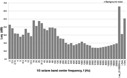
Background noise | 31,3 | 50,7 | 60,4 |
3. Noise and vibration measurements of FC PEM 6 kW
The following noise parameters were measured in the room where a fuel cell PEM 6 kW was mounted: – A-weighted, equivalent sound level; – C-weighted, equivalent sound level; – unweighted, equivalent sound level, as well as the spectrum of unweighted equivalent sound level in dB. ; ; (spectrum and dB) were also measured for the assessment of the background noise of the room. The time history of FC PEM 6 kW noise levels are shown in Fig. 3 and Fig. 4. The corresponding average spectrums of the noise levels are shown in Fig. 5. The time histories of background noise levels are shown in Fig. 6, and the corresponding average spectrums of noise levels are shown in Fig. 7. The results of sound insulation calculation for the most loudness operating status – no-load and load operations of FC PEM 6 kW are shown in Table 1.
Fig. 3Time courses of: sound pressure level, unweighted (Leq, 1 s, dB) – black line, sound pressure level, C-weighted (LCeq, 1 s, dBC) – gray line, sound pressure level, A-weighted (LAeq, 1 s, dBA) – discontinuous line, during the four cycles of FC PEM 6 kW work: start-up, no-load operation, load operation, withdrawal. Microphone 1, open enclosure
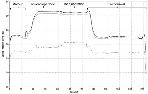
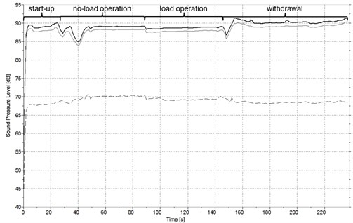
Fig. 4Time courses of: sound pressure level, unweighted (Leq, 1 s, dB) – black line, sound pressure level, C-weighted (LCeq, 1 s, dBC) – gray line, sound pressure level, A-weighted (LAeq, 1 s, dBA) – discontinuous line, during the four cycles of FC PEM 6 kW work: start-up, no-load operation, load operation withdrawal. Microphone 1, closed enclosure
4. Identification of noise sources of FC PEM 6 kV
The following sources of noise are predominant in the systems of PEM fuel cells:
– the pump which ensures the gas recirculation reaction and the circulation of the coolant;
– solenoid valves;
– fans and compressors;
– the coolant flow and reaction gases by elements of the installation.
Below is a brief description of the methods and achieved results.
Fig. 5The spectra of equivalent sound pressure level (Leq), unweighted during no-load and load operations of FC PEM 6 kW a) with closed enclosure, b) with open enclosure. Presented data correspond to Microphone 1
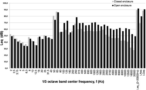
Fig. 6Time courses of: sound pressure level, unweighted (Leq, 1 s, dB) – black line, sound pressure level, C-weighted (LCeq, 1 s, dBC) – gray line, sound pressure level, A-weighted (LAeq, 1 s, dBA) – discontinuous line, background noise in room. Microphone 1
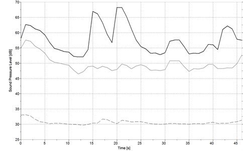
Fig. 7The spectrum of equivalent sound pressure level (Leq), unweighted of background noise in laboratory room. Microphone 1
4.1. Cross-correlation analysis of noise and vibration
The noise level of individual elements of the fuel cell varies with the regime of operation. Although measurements were performed for the following regimes: start-up, no-load operation, load operation, turn off the cell (all the regimes of the enclosure door open and closed doors – a total of 8 regimes work). They were the dominant source based on a full load regime with the door open housing. The purpose of the fuel cell is working in emergency. In such operating condition, other sources of electricity are turned off and the only source of electricity is based on cells. Typically, in the said state it is assumed to load from 50 to 75 % of rated power and hence the load condition is the most representative of the operation of the cell. The remaining operating states are short time states and it is assumed that the optimization of the noise level for the structure of the cell at this stage test is not necessary. Identification of the dominant source of noise consists of the following steps:
– The choice of place of the foundation sensors:
Accelerometers on the body (, , ), the hydrogen recirculation pump (, , ), and the cooling pump (, , ).
Microphone: at the same point as for determining the effectiveness of the sound insulating casing in the conditions of installation.
– Determination of the coherence function: A measure of the adequacy of the two signals (e.g. acceleration signal and noise signal ) is coherence. Matlab function “mscohere” is used for further computations. The magnitude squared coherence estimate is a function of frequency with values between 0 and 1 that indicates how well corresponds to at each frequency. The magnitude squared coherence is a function of the power spectral densities, and , of and ; the cross power spectral density of and [5] reads:
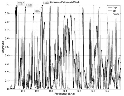
The coherence between hydrogen recirculation pump, cooling pump, the fuel cell casing and the noise signal measured by microphone No. 1 is illustrated in Fig. 8.
Fig. 8The coherence function between: hrc – hydrogen recirculation pump, cp – cooling pump, cover – cover of FC and the noise signal measured by Microphone 1
All calculations were done in Matlab using broadband signals. The Correlation block accepts two vector inputs. When and are sample-based column vectors with lengths and , the Correlation block performs the vector cross-correlation according to the following equation:
The dimensions of the sample-based output vector are determined by the dimensions of the input vectors: in this case both inputs are column vectors, the output is a ()-by-1 column vector [1].
Matlab function “xcorr” allows calculating the cross-correlation of two discrete-time sequences, e.g. digital signal of hydrogen recirculation pump and digital signal of microphone No. 1 and to determine the distance between two different sensors located at different points returns delay between two correlated signals. Results are expressed the delay as a number of samples and in seconds if the divide the number of samples corresponding to delay by the sampling frequency . Experimental formula for determining such relationship the speed of sound in dry air (humidity equal to zero) is given an approximate formula:
where: – speed of sound in dry air m/s; – temperature is in degrees Celsius during measurements (20° C).
Table 2Results of calculated distance between source and receiver
Accelerometer location | Open cover | Close cover | |||||
Distance to microphone No. 1 [mm] | |||||||
Real | Calculated | ||||||
Hydrogen recirculation pump | 920 | 1500 | 981 | 759 | 772 | 1058 | 435 |
Cooling pump | 820 | 266 | 545 | 1234 | 831 | 1344 | 805 |
Cover (left side from point of view measurement microphone) | 640 | 656 | 312 | 318 | 221 | 1130 | 1117 |
Fig. 9The cross-correlation function: between hrc – hydrogen recirculation pump and microphone No. 1
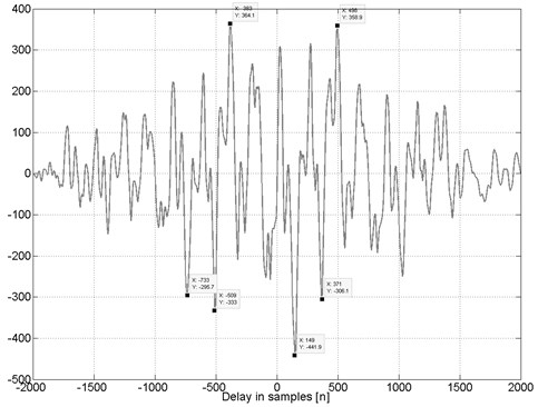
The delay time between the source (accelerometer) and the receiver (microphone) should be multiplied by the speed of sound in air to obtain the distance between them. Results are presented in Table 2. The table shows that the correct distance is obtained exclusively by the open door of an enclosure between the signals the acceleration of the hydrogen recirculation pump and signal noise recorded by the microphone No. 1. The results are shown in Fig. 9. Incompatibility distance remaining sources of noises due to the fact that both vibration and sound sensors recorded the common signal but the source of his not come from the place of the foundation vibration sensors.
5. Conclusions
The tested technology demonstrator is using fuel cell PEM 6 kW as reserve generator and is classified in the facilities complying with type “The panel of motor control and an emergency defense control room of the ship”, where the maximum sound pressure level at the speed of economic and maximum vessel must not exceed 70 dBA. The rules determine the permissible noise levels for vessels intended for military purposes are contained in documents [18, 19] and determine the limit values (maximum) the noise level to the premises and places on board the ship.
The conducted noise research shows that used enclosure is characterized by acoustic insulation above 10 dBA in the range of audible frequencies by human. As seen in Fig. 5 significant attenuation is in the range above 100 Hz. Low frequency noise in the range 2 to 100 Hz is greater in case of closed enclosure than in opened. This is probably related to the nature of work of the enclosure in this frequency band – enclosure works as a resonator (an amplifier). Equivalent sound pressure level at a distance of 0.5 m from the device under test, while no-load and load operation does not exceed the value of 69.2 dBA. Thus, the demonstrator meets the standard requirements. Further reduction of the emission of acoustic energy (sound power) by FC 6kW PEM is possible in the following ways: through the use of efficient sound isolation enclosures unit or by identifying relevant sources [21-24, 27, 28] by vibroacoustic analysis of individual unit elements generating vibrations [25, 26] and more reliable (e.g. with special shock absorbers) fixing elements of mechanical design and pipelines.
The calculations of coherence between hydrogen recirculation pump, cooling pump and the fuel cell casing and the microphone No. 1 shown in Fig. 8 confirmed the adequacy of the vibration signals and registered noise signal.
The results of cross-correlation calculations between hydrogen recirculation pump, cooling pump, the left side cover (from point of view measurement microphone No. 1) showed a convergence of noise sources and receiver but also confirm previous findings that the source of the noise are places outside of the designated locations accelerometers.
The investigation shows that the structure-born noise from pipes, supporting structures of the fuel cell should be considered as an important factor influencing acoustic fields. Further optimization of the structural elements of the fuel cell is an important objective of future research and should be seriously considered in industrial implementations.
References
-
Grzeczka G., Sobociński W. Hydrogen energy system as on energy source for navy ships. Polish Journal of Environmental Studies, Vol. 19, Issue 4A, 2010, p. 39-41.
-
Grzeczka G. Influence of exploitation way of lead-acid accumulators used on submarines on their durability. Polish Journal of Environmental Studies, Vol. 17, Issue 3C, 2008, p. 37-40.
-
Listewnik K. Some aspects of noise measurement of ships. Proceedings of the 20th International Congress on Sound and Vibration, Bangkok, Thailand, 2013.
-
Listewnik K. Sound silencing problem of underwater vehicles. Solid State Phenomena, Vol. 196, 2013, p. 212-219.
-
MATLAB. Signal Processing Toolbox User’s Guide. Mathworks Inc., http://www.mathworks.com/help/pdf_doc/signal/signal_tb.pdf, 2015.
-
ISO 10816-1:1995. Mechanical Vibration – Evaluation of Machine Vibration by Measurements on Non-Rotating Parts – Part 1: General Guidelines. 1995.
-
PN-EN 60994:1997. Guide for Field Measurement of Vibrations and Pulsations in Hydraulic Machines (Turbines, Storage Pumps and Pump-Turbines). 1997.
-
ISO 11546-1:1995. Acoustics – Determination of Sound Insulation Performances of Enclosures – Part 1: Measurements under Laboratory Conditions (For Declaration Purposes). 1995.
-
ISO 11546-2:1995. Acoustics – Determination of Sound Insulation Performances of Enclosures – Part 2: Measurements in Situ (For Acceptance and Verification Purposes). 1995.
-
ISO 11200:2014. Acoustics – Noise Emitted by Machinery and Equipment – Guidelines for the Use of Basic Standards for the Determination of Emission Sound Pressure Levels at a Work Station and at Other Specified Positions. 2014.
-
ISO 11202:2010. Acoustics – Noise Emitted by Machinery and Equipment – Determination of Emission Sound Pressure Levels at a Work Station and at Other Specified Positions Applying Approximate Environmental Corrections. 2010.
-
ISO 11204:2010. Acoustics – Noise Emitted by Machinery and Equipment – Determination of Emission Sound Pressure Levels at a Work Station and at Other Specified Positions Applying Accurate Environmental Corrections. 2010.
-
ISO 3740:2000. Acoustics – Determination of Sound Power Levels of Noise Sources – Guidelines for the Use of Basic Standards. 2000.
-
ISO 3743-1:2010. Acoustics – Determination of Sound Power Levels and Sound Energy Levels of Noise Sources Using Sound Pressure – Engineering Methods for Small Movable Sources in Reverberant Fields – Part 1: Comparison Method for a Hard-Walled Test Room. 2010.
-
ISO 3747:2010. Acoustics – Determination of Sound Power Levels and Sound Energy Levels of Noise Sources Using Sound Pressure – Engineering/Survey Methods for Use in Situ in a Reverberant Environment. 2010.
-
ISO 1683:2015. Acoustics – Preferred Reference Values for Acoustical and Vibratory Levels. 2015.
-
Engel Z., Sikora J. Sound Isolation Enclosures: Basis of Design and Use. AGH UST Press, Krakow, 1998, (in Polish).
-
NO-19-A203:2011. Naval Vessels and Auxiliary Surface Ships – Acoustic Environment of Ships – Requirements – Polish Implementation of STANAG 4293 Guidelines for the Acoustical Environment in NATO Surface Ships. 2011.
-
NO-63-A001:2014. Acceptable Levels a Sustainable Sound Battle Stations and Living Quarters Naval Vessels – General Requirements. 2014.
-
Batko W., Pawlik P. New method of uncertainty evaluation of the sound insulation of partitions. Acta Physica Polonica A, Vol. 123, Issue 6, 2013, p. 1012-1015.
-
Baranski R. Searching for new measurement solutions in the area of estimating danger of local vibrations at workplace. Acta Physcia Polonica A, Vol. 118, Issue 1, 2010, p. 3-6.
-
Klaczynski M. Identification of aircraft noise during acoustic monitoring by using 3D sound probes. Acta Physcia Polonica A, Vol. 125, Issue 4A, 2014, p. 144-148.
-
Klaczynski M., Wszolek T. Detection and classification of selected noise sources in long-term acoustic climate monitoring. Acta Physica Polonica A, Vol. 121, Issue 1A, 2012, p. 179-182.
-
Klaczynski M., Wszolek T. Artificial intelligence and learning systems methods in supporting long-term acoustic climate monitoring. Acta Physica Polonica A, Vol. 123, Issue 6, 2013, p. 1024-1028.
-
Cioch W., Knapik O., Leskow J. Finding a frequency signature for a cyclostationary signal with applications to wheel bearing diagnostics. Mechanical Systems and Signal Processing, Vol. 38, Issue 1SI, 2013, p. 55-64.
-
Jamro E., Cioch W. Digital signal acquisition and processing in FPGAs. Przegląd Elektryczny, Vol. 85, Issue 2, 2009, p. 7-9.
-
Burdzik R. Implementation of multidimensional identification of signal characteristics in the analysis of vibration properties of an automotive vehicle’s floor panel. Eksploatacja i Niezawodność – Maintenance and Reliability, Vol. 16, Issue 3, 2014, p. 439-445.
-
Burdzik R., Konieczny L. Application of Vibroacoustic Methods for Monitoring and Control of Comfort and Safety of Passenger Cars, Mechatronic Systems, Mechanics and Materials II. Book Series: Solid State Phenomena, Vol. 210, 2014, p. 20-25.
About this article

