Abstract
Firstly, FEM (Finite Element model) of the aluminum profile is built. The structural material parameters are then given to compute the free modals. After the comparison with the experimental results, the relative error of the modal frequency can be controlled within 5 %, which meets the requirements of CAE analysis. Secondly, pulse decay method is applied to measure damping loss factor of the aluminum profile. As shown from the results, its damping loss factor is 0.15 %-0.35 % within 0 Hz-1600 Hz, which can be used as the input parameter in the subsequent computation of the transmission loss. Thirdly, FE-SEA hybrid method is used to compute the transmission loss of the aluminum profile. As known from the computational results, the transmission loss troughs of the aluminum profile are appeared at 160 Hz, 400 Hz and 800 Hz, whose change trend is basically consistent with the experimental results. Therefore, the sound insulation performance of the aluminum profile at middle and low-frequency band can be reasonably predicted by the simulation model. Finally, based on the verified model of the aluminum profile, the optimization design is conducted on its acoustic-vibro performance from the following aspects such as sound-bridge, plate thickness and structural materials. As a result, a structure with relatively optimal acoustic-vibro performance is obtained.
1. Introduction
The lightweight technology of the high-speed train has been a key technique for their developments. In recent years, the advances of the aluminum profile have allowed it to be the leading material of the high-speed train [1-3]. As the ribbed plate, the aluminum profile can reduce the weight of the high-speed train. Meanwhile, many cross members are also reduced by the aluminum profile. Yu [4] and Yang [5] have conducted on the simulation analysis for the interior noises of the high-speed train. As shown from the results, the interior noises mainly come from vibration of the plates. Therefore, it is very necessary to optimize the aluminum profile structure of the high-speed train and improve its sound insulation performance. Based on FE-SEA hybrid method and periodic sub-structure principle, references [6, 7] have built the simulation model of sound insulation performance for the aluminum profile of the high-speed train, in order to analyze its sound insulation performance under different sound-bridge angles. Experiments of sound insulation performance for three kinds of aluminum profiles are conducted by Shen, and the corresponding requirements are then proposed for its sound insulation performance based on the spectral characteristics of sound source [8].
By means of the finite element and boundary element method, Kohrs has computed sound insulation performance of the aluminum profile. However, with the increasing frequency, the local modals of the web dominate and the modals of the entire plate get complicated [9, 10]. Xie has built SEA model of sound insulation performance for the aluminum profile. However, the predictive result of sound insulation performance is quite ideal under force loading, while it is not ideal under sound. The interior noises of the high-speed train are mainly in the middle and low- frequency. More local models are appeared in comparison with the low-frequency problem, and individual structures cannot entirely meet the requirements raised by SEA. Therefore, the interior noises have more significant middle and low-frequency characteristics, which belong to the typical middle frequency problem [11, 12]. As a result, FE-SEA hybrid method is proposed by Langley. The advantages when it handles the low frequency problems of FEM are combined with SEA superiority, in order to solve the middle frequency problem [13-16]. Based on references [13], Cotoni has built FE-SEA hybrid model of the aluminum profile and made the corresponding verification by the numerical method [17]. After proposing the periodic sub-structure, Mead has conducted on a lot of researches and made the theoretical analysis and experimental verification for the aluminum profile [18, 19].
2. FE-SEA basic theory
2.1. Reciprocal relation of subsystems
The system will be divided into many meshes when the dynamic response of system is analyzed by the finite element method. Each node will generate the corresponding displacement in the various degrees of freedom. On the boundary, the displacement in the boundary degree of freedom can be expressed as follows [11]:
where is the external excitation, and is the stiffness matrix.
Elastic waves generated by the boundary harmonic vibrations are propagated through system to the boundary region for reflection. In the dynamic stiffness matrix , the part without reflection is defined as the direct dynamic stiffness matrix , and there is a difference of “reverberation” force between the boundary force and the actual boundary force as follows:
Eq. (2) is then substituted into Eq. (1) to obtain the following formula [20]:
where, the subscripting “” means “reverberation”, and “” represents direction.
Based on wave propagation theory, the following formula can be obtained if the sound field is the diffusion field:
where, is the mean value of all structures, and is the vibration energy of the plate subsystem. is the modal density of the subsystem. The superscripting indicates the matrix transpose, and represents the imaginary part. Therefore, Eq. (4) is the reciprocity relation of the diffusion field.
2.2. Hybrid FE-SEA system function
The coupling effect between FE subsystem and SEA subsystem can be expressed by Eq. (4). The response of the deterministic system can be expressed as follows:
where, is the dynamic stiffness matrix of FEM subsystem, and indicates the mutual spectral of excitation force applied to FEM subsystem. means the average dynamic stiffness matrix of the subsystem. is the vibrational energy of the subsystem . is the modal density of the subsystem . is the angular frequency. The subscripting represents the deterministic system, and the subscripting indicates the mutual spectra. The subscripting and superscript means th subsystem. The subscripting means the dynamic stiffness, and the subscripting means the total dynamic stiffness. Since the power of each subsystem is balanced, the power balance equation of FE-SEA coupling system is as follows [12]:
where is the damping loss factor of the subsystem , and is the input power of the subsystem . is the input power generated from the force which is applied on the deterministic system. is the coupling loss factor of subsystem and . The subscripting and represent the th and th subsystem, respectively. According to Eq. (7), the energy response of the system can be obtained, and the responseof the deterministic system can also be obtained from Eq. (5).
3. Experiment of the transmission loss for the aluminum profile
Transmission loss can be obtained by means of Eq. (8). In the formula, is the incidence power, and is the transmission power [9]:
As shown in Fig. 1, the aluminum profile is fixed on a window between two reverberation chambers to test its transmission loss.
3.1. Sound pressure method
where is the average value of sound pressure level in the incidence side. is the average value of sound pressure level in the transmission side. is the surface area of the wooden component. is sound absorption. is volume of reverberation chamber. is reverberation time. The detailed experiment process can refer to reference [21].
3.2. Sound intensity method
The computational formula for sound intensity is as follows. is the transmission intensity, is density, and is sound speed in air. The other parameters have been described in the above:
Fig. 1Experimental process of transmission loss
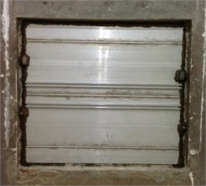
a) The incidence side
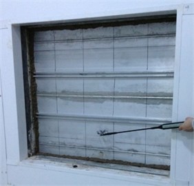
b) The transmission side
Fig. 2Comparison of experimental result for two methods under 1/3 octave
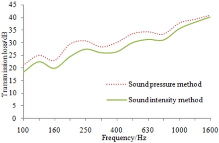
As shown from Fig. 2, the transmission loss of the aluminum profile is obtained by the sound pressure and sound intensity methods. It can be found that two curves have shown the consistent trends, while the transmission loss is differed about 3 dB at middle and low-frequency band below 1000 Hz, which may be related to the installation state of the experimental plate. As hooks are existed at both ends of the aluminum profile structure, the sealing of the aluminum profile and installation is hard to be made. Under the actual installation conditions, there may be sound leakage which affects less on far-field sound pressure but larger on near-field sound intensity. As a result, the radiation sound power is large and the transmission loss is small. Therefore, transmission loss obtained by sound intensity method would be lower than that obtained by sound pressure method in middle and low-frequency band. In addition, the transmission loss of the aluminum profile has shown a steady upward trend. Moreover, transmission loss at the frequency below 800 Hz is slowly increased, while that at the frequency over 800 Hz is rapidly improved. Therefore the coincidence frequency of transmission loss for the aluminum profile is about 800 Hz.
4. Numerical computation of the transmission loss for the aluminum profile
4.1. The finite element model of the aluminum profile
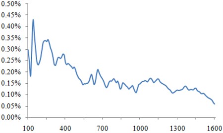
Damping loss factor is an important parameter for the finite element model. As a result, it should be measured. In this paper, it is measured as shown in Fig. 3 according to the method proposed by reference [21].
Fig. 3Damping loss factor of the aluminum profile
As shown in Fig. 4, the aluminum profile is a special structure which is made of two aluminum plates connected by sound-bridge. Considering the important impact of sound bridge on the vibration energy, some geometric characteristics will be missed due to building two-dimensional model. As a result, the computational model of the aluminum profile is built by using three-dimensional, as shown in Fig. 5. The structural and material parameters are shown in Table 1.
Fig. 4Geometric characteristics of the aluminum profile
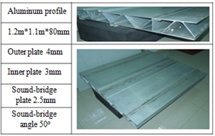
Fig. 5Three-dimensional model of aluminum profile
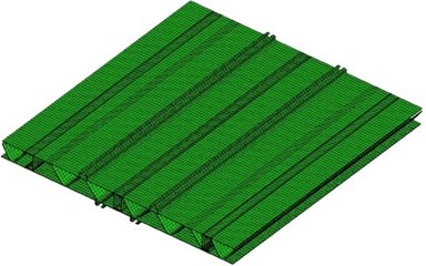
Table 1Structural and material parameters of the aluminum profile
Panel | Element type | Number of elements |
Aluminum profile | 6-node pentahedron, 8-node hexahedron | 44320 |
Physical parameters | Material parameters | Units |
Bulk density | 2685 | kg/m3 |
Young’s modulus | 7.24e10 | Pa |
Poisson’s ratio | 0.3 | – |
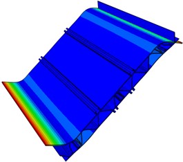
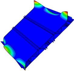
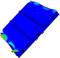
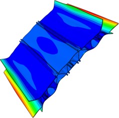
In order to verify the accuracy of the finite element model, the free modal test is conducted on the aluminum profile. Multi-points excitation and single-point response are adopted in the test. The aluminum profile is hung with a flexible rope, and the collection points are arranged in the positions with greater structure response. Besides, each excitation point is hammered three times. Frequency response functions with better consistency are selected. Finally, all frequency response functions are conducted on modal fitting to obtain modal parameters of the aluminum profile. The simulation and experimental results of free models are compared to verify the reliability of the finite element model, whose models are shown in Fig. 6.
As seen in Fig. 6, the first order modal refers to the torsional vibration. The second and third order modals are the bending vibration. The fourth and fifth order modals mainly show the torsional vibration at both ends, and the sixth order modal is the composite vibration. Among them, the positions with maximum amplitude are concentrated on both ends of the plate, because the aluminum profile is cut according to the experimental requirements and sound-bridge on both ends is not connected with the upper surface. As a result, the structure is weak in the both ends and easily generates the local vibration.
Fig. 6Modal shape of the first six orders for the aluminum profile
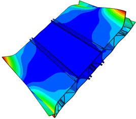
a) First order
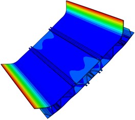
b) Second order
c) Third order
d) Fourth order
e) Fifth order
f) Sixth order
4.2. Selection of computational method and verification of transmission loss
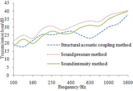
The structural-acoustic coupling method is also applied in the paper to calculate the transmission loss of the aluminum profile, whose simulation model is shown in Fig. 7. It can be seen that meshes of three-dimensional sound cavity are established on both sides of the finite element model of the aluminum profile in order to simulate the sender chamber and receiving chamber respectively. As known by Principle of 1/6 Wavelength, the maximum length of sound cavity element is 28 mm, which satisfies the calculation accuracy within 2000 Hz. In the process, all outer surfaces of the sound cavity are endowed with the attributes of self-adaptive matching layer in order to completely absorb and radiate sound power. And the structural meshes of both the inner surface and aluminum profile are defined as the structure-acoustic coupling surfaces to transfer the acoustic energy. The original boundary conditions applied by the simulation are simply-supported constraints for four longitudinal edges along the sound bridge, as well as the excitation source of 1 Pa reverberant sound at the incident side. Finally, the calculation results are compared with the experimental result, as shown in Fig. 8. It can be seen that better consistency can be found in the low frequency within 400 Hz while unreliable simulation result is appeared in the frequency range of more than 400 Hz. Such result can be explained by the complex structure of the aluminum profile that has many sound bridge structures rather than a regular panel. Therefore, the structural modal would be very intensive when the analyzed frequency is more than 400 Hz, thus resulting in serious errors by means of FEM techniques at this time.
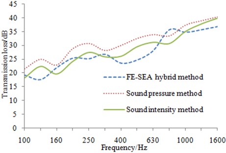
Based on the mentioned analysis, FE-SEA hybrid method is also applied in the paper to compute the transmission loss of the aluminum profile, as shown in Fig. 9. The upper and lower panels, sound bridges and other substructures of the aluminum profile are firstly divided into different mesh sets in the finite element software HYPERMESH, and then applied appropriate constraints. Later, the finite element model is imported into VAONE, and different mesh sets are selected to generate the corresponding subsystems. In the generation of the finite element subsystem, meanwhile, FE Face can be generated automatically from the software. At the incident side, 1 Pa reverberant sound source is applied on the FE Face in order to simulate the noise source in the experiment. In addition, semi-wireless fluid fields which are equivalent to SEA subsystem are defined at the incident side and transmission side respectively, in order to collect the radiation sound energy of the aluminum profile structure. After obtaining FE-SEA hybrid model of the aluminum profile, the transmission loss at the 1/3 octave band is computed in the software directly, as shown in Fig. 10. As can be seen Fig. 10, better consistency is found between the simulation and experimental results, thus indicating that the calculation method is obviously better than the traditional structural-acoustic coupling method.
Fig. 7Structural-acoustic coupling model of the aluminum profile
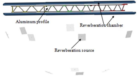
Fig. 8Simulation and experimental comparison of transmission loss
In addition, it can be seen at the middle and low-frequency between 100 Hz-1600 Hz, the simulation and experimental results are basically same in the change trend. For the experimental value, three insulation troughs which are 160 Hz, 315 Hz and 800 Hz are presented. However, the second insulation trough of the numerical results is at 400 Hz, this is caused by the differences in boundary conditions. In addition, the transmission loss obtained by sound pressure method is always higher than that of sound intensity method, and the difference is about 2.5 dB. Transmission loss curve obtained by the simulation is more close to the result of sound intensity method at the frequency band below 315 Hz, and more close to the result of sound pressure method at the frequency band over 630 Hz. Therefore, FE-SEA hybrid method is reliable to be predicted the transmission loss of the aluminum profile at the middle and low-frequency.
Fig. 9FE-SEA hybrid model of the aluminum profile
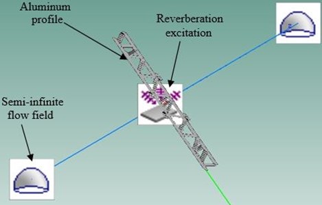
Fig. 10Simulation and experimental comparison of transmission loss
5. Parameter analysis of the transmission loss for the aluminum profile
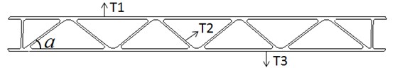
The transmission loss of the aluminum profile is easily studied based on the verified model. The cross section of the aluminum profile, as shown in Fig. 11, is comprised of trapezoidal sound bridge, upper and lower panels. Therefore, researches on these structures should be conducted necessarily in order to observe the change principle of the transmission loss for the aluminum profile.
Fig. 11Sectional characteristics of the aluminum profile
5.1. Structural design
The aluminum profile of the high-speed train is comprised of the upper and lower panels as well as the middle sound bridge. Since the upper and lower panels are the regularly planar structure, the geometric design towards them is of no significance. Therefore, the structural design of the aluminum profile is mainly reflected in the design of sound bridge. Currently, the sound-bridge forms of the aluminum profile are mainly divided into triangular, trapezoidal and quadrilateral.
The overall height of the aluminum profile and the thickness of each plate are remained constantly. Then the trapezoidal structure is attempted to change into quadrilateral and triangular structure as shown in Fig. 12, and the corresponding transmission loss is also calculated, whose results are shown in Fig. 13.
Fig. 12Cross sections of the aluminum profile with two kinds of sound bridges

a) Cross section of the aluminum profile with quadrangular sound bridge

b) Cross section of the aluminum profile with triangular sound bridge
Fig. 13Comparison of transmission losses for the aluminum profile with two kinds of sound bridges
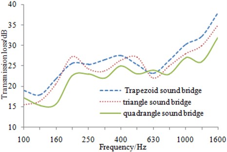
Triangular and trapezoidal sound bridges are of little difference as can be seen from Fig. 11 and Fig. 12. The trapezoidal structure is only featured with a smooth transitional cycle on the top, similar to the triangular structure. However, the external excitation can be better attenuated by such transitional cycle in the actual project, and the transmission loss reflected by the trapezoidal structure can be found in Fig. 13. The transmission loss of the aluminum profile with the trapezoidal sound bridge is higher than that of the triangular structure in most frequency points, except 200 Hz and 500 Hz where the transmission loss of the aluminum profile with the triangular sound bridge is increased by 2.3 dB and 2.1 dB respectively when it is compared to the original structure. It can be possibly explained by the modal changes at these frequency points caused by the minor structural changes. The average transmission losses of both trapezoidal andtriangular sound bridges are 26.1 dB and 24.7 dB, respectively, thus further indicating the better sound insulation effect of trapezoidal sound bridge. In addition, relatively small amplitude of the transmission loss and relatively concentrated modal density can be found in the entire frequency band for the aluminum profile with quadrilateral sound bridge. It is mainly because quadrilateral structure has poorer stability and relatively concentrated modal density than the triangular structure, thus reflecting more peaks and valleys in terms of the transmission loss curve. The average transmission loss of the quadrilateral bridge is 22.8 dB, significantly smaller than the mentioned two structures. In combination with the above analysis, it can be found the reasonability of trapezoidal sound bridge applied in the aluminum profile structure of the high-speed train.
5.2. Sound-bridge angle
The original section characteristics of the aluminum profile are shown as Fig. 11. Sound-bridge angle is 35° and it has 8 sound-bridges. The thickness of each plate remains unchanged, sound-bridge angle is increased to 60° with 5° as the step length, and two-dimensional model of the aluminum profiles is built, and the basic parameters are shown as Table 2.
Table 2Structural parameters of the aluminum profile under different sound-bridge angle
Basic dimensions | 4 mm, 2.5 mm, 3 mm | |||||
Sound-bridge angle (°) | 35 | 40 | 45 | 50 | 55 | 60 |
First order torsion (Hz) | 334.4 | 340.1 | 341.3 | 339.7 | 335.4 | 329.6 |
First order bending (Hz) | 361.1 | 371.2 | 376.5 | 379.3 | 378.3 | 376.7 |
Mass (kg) | 16.63 | 17.17 | 17.64 | 18.09 | 18.92 | 19.70 |
Number of sound-bridge | 8 | 10 | 12 | 14 | 17 | 20 |
Number of modes | 205 | 150 | 124 | 71 | 18 | 12 |
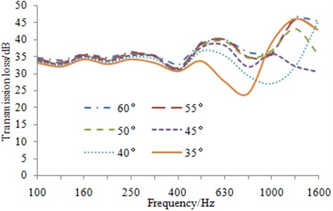
Similarly, FE-SEA hybrid method is applied to compute sound insulation performance of the aluminum profile under free boundary conditions, whose result is shown in Fig. 14. First of all, it is shown from Table 2 that although sound-bridge angle of the aluminum profile is increasing, the first order torsion and bending frequency has shown little change under free boundary condition. Therefore, it is reflected that the result of 1/3 octave spectrum has illustrated sound insulation trough concentrated at 400 Hz, as shown in Fig. 14. Before the first order torsional frequency, the transmission loss is quite gentle, and acoustic waves in the vertical section are equivalent to that passing through three layers of the aluminum plate. Therefore, the transmission loss is proportional to the number of sound-bridge. After 400 Hz, the transmission loss is more affected by mass law and structure resonance. With the increase of sound-bridge angle, especially after 50°, the modals number of the aluminum profile is significantly reduced. Transmission loss frequency is in conformity to mass law in all spectrums except the trough of modal frequencies. As can be seen in Fig. 14, the transmission loss is improved along with the increase of sound-bridge angle. Generally speaking, the aluminum profile at 55°-60° can be chosen for regions with higher structural strength, and transmission loss can be ensured at better level. However, the aluminum profile at 35°-40° can be selected when structural lightweight is the important index. Though the sound insulation performance of the structure itself is sacrificed, sound package can be applied for improving the sound insulation performance.
Fig. 14Transmission loss curve of the aluminum profile under different sound-bridge angles
5.3. Plate thickness
Based on the above analysis, 55° is chosen as sound-bridge angle. The basic geometric dimension is remained the same, the thickness of inner plate, sound-bridge plate and outer plate is chosen as variable, and structure-acoustic coupling method is applied to study the acoustic performance of the aluminum profile under the free boundary constraint.
Fig. 15Transmission loss with different plate thicknesses
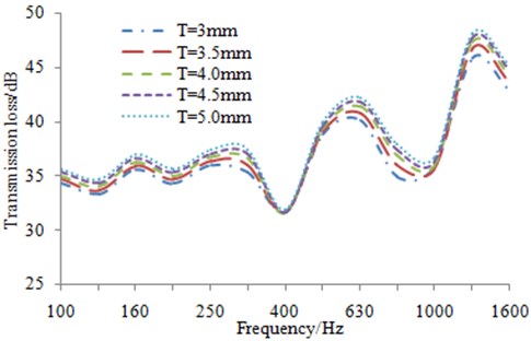
a) Transmission loss with inner panel thickness
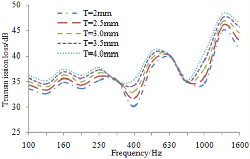
b) Transmission loss with sound-bridge plate thickness
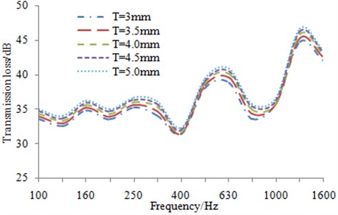
c) Transmission loss with outer plate thickness
Since the lightweight of the high-speed train is affected by the plate thickness directly, the allowed change scope is very limited. Considering that the combination of 3 mm outer plate, 2.5 mm sound-bridge plate and 4 mm inner plate is mostly applied in the structure of the original high-speed train, the thickness range of outer plate, sound-bridge plate and inner plate is defined as 3 mm-5 mm, 2 mm-4 mm and 3 mm-5 mm, respectively, and the corresponding step length is 0.5 mm. The simulation result of the transmission loss is shown in Fig. 15. As shown from Fig. 15, it is indicated that after increasing thickness for inner and outer plate of the aluminum profile, modals frequency and transmission loss trough have a little change. But structural mass and surface density are increased meanwhile, therefore transmission loss at other frequency bands is improved. And the maximum optimization value at the central frequency band of a single one-third octave band is about 3 dB. Therefore, on the premise of requirements for the structural strength and lightweight indexes of the aluminum profile, the appropriate thickening treatment is conducted for sound-bridge plate, which is a reasonable solution to optimize the sound insulation performance of the aluminum profile.
5.4. Structural material
Steel, aluminum and magnesium are three kinds of commonly-used structural materials. Initially, trains used high-strength steel and stainless steel as the body structure. Afterwards, the aluminum alloy became the preferred material of high-speed trains due to its advantages such as small proportion and high strength. As a kind of new lightweight material, magnesium alloy is applied in the field of aerospace and automobile in the past. This paper takes the same structure as the research object and compares the advantages and disadvantages in terms of vibration and acoustic performance by means of replacing materials. The basic material parameters are shown in Table 3.
Table 3Material parameters of three kinds of metals
Parameter | Material | ||
Aluminum alloy | Magnesium alloy | Steel | |
Elastic modulus (Pa) | 7.24e10 | 4.5e10 | 2.1e11 |
Bulk density (kg/m3) | 2685 | 1750 | 7800 |
Poisson’s ratio | 0.3 | 0.33 | 0.28 |
Damping loss factor | 1e-3 ~ 4e-3 | 2e-4 ~ 2.5e-3 | 1e-4 ~ 6e-4 |
Fig. 16Transmission loss curves of the structure with three kinds of materials
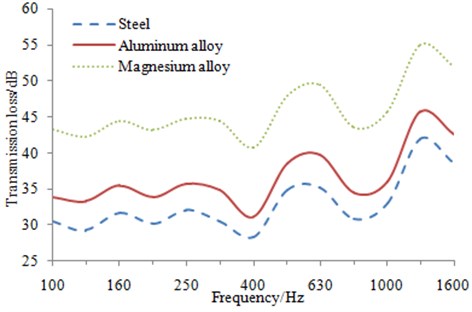
The simulation result of the transmission loss is shown in Fig. 16, which shows that the structures with different materials present obvious differences under the same volume. Steel has maximum bulk density and also the best sound insulation performance under the influence of mass law. The second is the aluminum alloy whose transmission loss is about 9 dB less than that of steel. Magnesium alloy will be the last one, due to its minimum bulk density and mass. Magnesium alloy is around 3.5 dB less than aluminum alloy in terms of transmission loss. The free modal frequencies of three kinds of materials do not differ much. Therefore, the sound insulation trough also stays the same basically. In the practical engineering, the bulk density of steel is about three times that of the aluminum alloy and it is very difficult to satisfy the demand of high-speed trains for lightweight. Magnesium alloy is only 2/3 the bulk density of that of aluminum alloy, but its panel needs to be thickened in order to reach the same transmission loss. In addition, magnesium alloy is usually used in the structural parts without high demand for impact resistance as its structural hardness is still flawed. Therefore, the structure which is designed by adopting aluminum alloy materials is the most reasonable main structure of high-speed trains.
6. Conclusions
1) FEM of the aluminum profile is built. The structural material parameters are given to compute the free modal. After the comparison with the experimental result, the relative error of the modal frequency is very little, and this can meet the requirements of CAE analysis. Therefore, this finite element model is reliable.
2) Pulse decay method is applied to measure damping loss factor of the aluminum profile. As shown from the results, its damping loss factor is 0.15 %-0.35 % within 0 Hz-1600 Hz, which can be used as the input parameter in the subsequent computation of the transmission loss.
3) FE-SEA hybrid method is applied to compute the transmission loss of the aluminum profile. As known from the results, the transmission loss troughs of the aluminum profile are presented at 160 Hz, 400 Hz and 800 Hz, whose change trend is basically consistent with the experimental results. Therefore, the sound insulation performance of the aluminum profile at middle and low-frequency band can be reasonably predicted by the simulation model.
4) Based on the verified simulation model of the aluminum profile, the optimization design is conducted for its acoustic-vibro performance from the following aspects such as sound-bridge, plate thickness and structural materials. As a result, a structure with relatively optimal acoustic-vibro performance is obtained.
References
-
Zhang Y. Y., Shen H. M., Xiao X. B. Research on vibration and transmission loss of aluminum alloy external floor for high-speed train. Journal of Chongqing University of Technology (Nature Science), Vol. 28, Issue 1, 2014, p. 28-32.
-
Chen J. Y., Lin Q. Z., Shen L. L. An immune-inspired evolutionary strategy for constrained optimization problems. International Journal on Artificial Intelligence Tools, Vol. 20, Issue 3, 2011, p. 549-561.
-
Liang Z. P., Song R. Z., Lin Q. Z., Du Z. H., Chen J. Y., Ming Z., Yu J. P. A double-module immune algorithm for multi-objective optimization problems. Applied Soft Computing, Vol. 35, 2015, p. 161-174.
-
Yu Y., Xiao X. B., Jin X. S. Prediction of interior noise in a cabin of high speed train using FE-SEA hybrid methods. Inter-Noise11, Osaka, 2011.
-
Yang J., Zuo Y. Y., Chang Q. B. The body structure dynamic characteristics and acoustic modal analysis of A-type metro vehicle. Noise and Vibration, Vol. 31, Issue 3, 2011, p. 76-79.
-
Shen H. M., Zhang Y. M., Xiao X. B. Low-noise optimization design of external corrugated floor for high-speed train. Journal of Traffic and Transportation Engineering, Vol. 11, Issue 2, 2011, p. 65-71.
-
Chen J. Y., Lin Q. Z., Hu Q. B. Application of novel clonal algorithm in multi-objective optimization. International Journal of Information Technology and Decision Making, Vol. 19, Issue 2, 2010, p. 239-266.
-
Shen Y. X. Simulation and Experiment Research of Sound Insulation Performance for Floor Structure of High-Speed Train. Beijing Jiaotong University, Beijing, 2009.
-
Kohrs T. Structure Acoustic Investigation of Orthotropic Plates. Technical University of Berlin, Berlin, 2002.
-
Li J. Q., He S. Q., Ming Z. An intelligent wireless sensor networks system with multiple server’s communication. International Journal of Distributed Sensor Networks, 2015, p. 960173.
-
Xie G. The Vibro-Acoustic Behavior of Aluminum Extrusions Used in Railway Vehicles. University of Southampton, Southampton, 2004.
-
Xie G., Thompson D. J., Jones C. J. C. A modelling approach for the vibro-acoustic behavior of aluminum extrusions used in railway vehicles. Journal of Sound and Vibration, Vol. 293, Issue 3, 2006, p. 921-932.
-
Langley R. S., Bremner P. A hybrid method for the vibration analysis of complex structural-acoustic systems. Journal of the Acoustical Society of America, Vol. 105, Issue 3, 1999, p. 1657-1671.
-
Langley R. S. The response of two-dimensional periodic structures to point harmonic forcing. Journal of Sound and Vibration, Vol. 197, Issue 4, 1996, p. 447-469.
-
Langley R. S. The response of two-dimensional periodic structures to impulsive point loading. Journal of Sound and Vibration, Vol. 201, Issue 2, 1997, p. 235-253.
-
Langley R. S., Bardell N. S. The response of two-dimensional periodic structures to harmonic point loading: a theoretical and experimental study of a beam grillage. Journal of Sound and Vibration, Vol. 207, Issue 4, 1997, p. 521-535.
-
Cotoni V., Langley R. S., Shorter P. J. A statistical energy analysis subsystem formulation using finite element and periodic structure theory. Journal of Sound and Vibration, Vol. 318, Issue 4, 2008, p. 1077-1108.
-
Mead D. J. Wave propagation in continuous periodic structures: research contribution from Southampton. Journal of Sound and Vibration, Vol. 190, Issue 3, 1996, p. 495-524.
-
Wang J., Lu T. J. Sound transmission through lightweight double-leaf partitions: theoretical modelling. Journal of Sound and Vibration, Vol. 286, Issue 6, 2005, p. 817-847.
-
Lin Q. Z., Zhu Q. L., Huang P. Z., Chen J. Y., Ming Z., Yu J. P. A novel hybrid multi-objective immune algorithm with adaptive differential evolution. Computers and Operations Research, Vol. 65, 2015, p. 95-111.
-
Hao Z. Y., Ding Z. Y., Sun Q. Sound insulation performance of the silent floor of high-speed train based on FE-SEA hybrid method. Journal of Jilin University (Engineering and Technology Edition), Vol. 45, Issue 4, 2015, p. 1069-1075.
Cited by
About this article

