Abstract
This paper proposed a low cost flexible electro-dynamic planar loudspeaker (FEPL). The structure is very simple such as a flexible thin film diaphragm (polyimide) electroplated traces of copper coil above a flexible magnetic placed in the bottom of cavity, thus forming a seamless integration of electromagnetic actuation and planar flexible structure. The advantage is that it can be used in flexible electronics or can be deployed on the surface of any object easily. To optimize the performance, this study made detailed analyses on the thickness of cavity, magnet and coil, magnet polarization, and diaphragm dimension. Note that as the cavity height increasing, the magnetic flux densities of both vertically and horizontally polarized magnet are decreased. But they are nearly constant over the surface with the same height for the vertically polarized magnet. On the other hand, as the cavity height of the horizontally polarized magnet increases, the magnetic flux densities would be decrease rapidly at the locations moving farther away from the center point. These effects are not discussed in previous literature of study.
1. Introduction
Flexible electronics has been a hot research and development topic in the electronics industry since the past few years. This is due to the rapid growth of flexible electronic technology [1, 2]. The speaker is an important part of the electronics and has received many attentions [3-11]. Some progresses have been made towards the development of flexible loudspeaker, and most of them have failed for commercial production. In loudspeaker design, many different actuation mechanisms are employed for electro-acoustic transduction, such as electromagnetic [4, 12-16], piezoelectric [5, 6], electrostatic [8, 17], and electro-thermal [18-19] actuation mechanism. The flexible and transparent loudspeakers using piezoelectric actuation mechanism were developed [3, 5] by using PVDF as the piezoelectric polymer as radiator. Results of their study showed that the PVDF driven flexible loudspeaker were able to produce 70dB and 80dB SPLs within a frequency range of 1-20 KHz and 400 Hz-10 KHz, respectively. However, PVDF material is very expensive due to the complex production process [6]. They are of high frequency speakers and difficult to produce sound in low frequency range. Industrial Technology Research Institute (ITRI) Taiwan in 2009 filed a patent [17] of an electrostatic actuated ultrathin flexible loudspeaker, it was able to produce sound within 200 Hz-20 KHz, and thus can be operated in medium and high frequency [11]. They combined arrays of tiny, bendable speakers to produce speaker systems of almost any size using standard inkjet printing on substrate of paper or plastic and a thin metal. Though suffers the same fate as PDVF loudspeaker in producing low frequency sound. Furthermore, other industrial based developed flexible loudspeakers include Yamaha Corporation [9] and Warwick audio technologies [10] that developed an electrostatic directional flexible loudspeaker capable of producing sound only in a specified direction. Fujifilm [8] also developed an electro-acoustic film which also operates using electrostatic mechanism. The inspired work of Xiao et al. [19] brought to light a flexible, stretchable, transparent loudspeaker designed using carbon nano-tubes (CNT). It operates using the electro-thermal mechanism. But this loudspeaker has a major drawback for the lack of industrial process to create thin films of CNTs. Until now electromagnetic actuation mechanism has not been explored in designing flat flexible loudspeaker that can be used in pop up banners, portable exhibition stands and other uses that require flat flexible loudspeaker.
This study has explored the possibility to develop a flexible electro-dynamic planar loudspeaker using finite element analysis in COMSOL. Over the years, electromagnetic actuation has been proven to be the most efficient actuation mechanism to generate sound pressure [4-13]. In general, the electro-dynamic loudspeakers generate sound through the interaction of a magnetic field, usually created by a rigid permanent magnet (neodymium magnet), with a coil of wire carrying an audio current and attached to a diaphragm. The proposed design adopts the structure of a single ended planar loudspeaker which is an electro-dynamic loudspeaker [7, 14]. Therefore, the challenge is how to utilize this actuation mechanism and structure to achieve a flexible loudspeaker. An explosive structure of the proposed design is shown in Fig. 1(a). The core structure is the substitution of the conventional rigid magnet with a flexible magnet made of mixture of polymer and neodymium (NdFeB) or ferrite material. According to the up-to-date technology it is obtainable to have flexible magnets that have up to 1.8 MgOe (2730 gauss) or more [21-24]. This is relatively good for flexible loudspeaker applications when all other militating factors are put to check as will be shown later. Besides, an ultrathin flexible polyimide (PI) film was adopted as the diaphragm with a copper coil electroplated on one side of its surface. Using COMSOL the 3D model was applied; the material properties such as the PI diaphragm and the permanent magnet of neodymium could be selected in the sub-domain settings and defined in Section 2. Following the sub-domain setting, the boundary conditions were specified. The outer boundary of diaphragm is fixed, while the remaining surfaces and edges are allowed to move freely. The locations of the testing points of SPLs in this paper are 10cm from the center of the diaphragm; and the magnetic fields are measured in two dimensions and located above the speaker surface lying in the vertical planes along the center axes of the diaphragms. The monopole source model and the governing equations can be applied as defined in COMSOL [23]. So the Helmholtz equation for the acoustic pressure simulation, Navier-Stokes equation for the stress and strain simulations, acoustic-solid interaction, and frequency domain analysis can be done. Besides, we chose the 2D triangle as the basic shape of the grid, which can generate the 3D tetrahedron, the numbers of the meshes at the terminals and boundaries are set as 204 and 505, respectively. The meshed geometry of the baseline loudspeaker is as shown in Fig. 1(b). In this paper an one volt audio signal is applied to the coil on the diaphragm of loudspeaker, by Ampere’s law and the COMSOL package, an AC magnetic field can be generated, which can interact with the permanent magnet at the bottom of cavity to generate repulsive and attraction forces on the diaphragm. Thus one can measure the SPLs for the design.
Fig. 1Proposed FEPL: a) explosive structure, and b) meshed geometry of loudspeaker (side view)
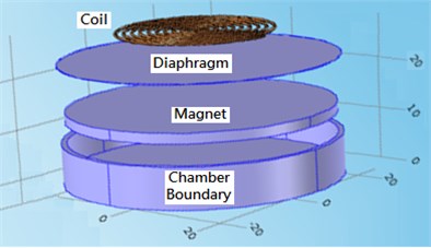
a)
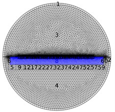
b)
This study made a detailed mechano-acoustic and electrodynamic analyses by using finite element simulation method on the thickness of cavity, diaphragm dimension, and magnet field configuration (such as vertically (axially) and horizontally (radically) polarized respectively, which are scarcely discussed in previous literatures. The paper is organized as follows: the first section is an introduction; the next part illustrates the FEPL structure configuration and optimization method; Section 3 is results and discussions; the last part is a conclusion.
2. FEPL structure configuration and design
First of all, the polyimide was chosen as the diaphragm material because its temperature is endurable to 200 °C and light weight. The density, coefficient of thermal expansion and thickness of the diaphragm are as 1430 kg/m3, 5.5×10⁻⁵/ K and 0.122 mm, respectively. The core structure is the substitution of the conventional rigid magnet with a flexible magnet made of mixture of polymer and neodymium (NdFeB) or ferrite material. Right now it is able to get flexible magnets that have up to 1.8MgOe (2730 gauss) or more [21]. This is relatively good for flexible loudspeaker application when all other militating factors are put to check as will be shown later. Besides, the copper coil is electroplated on the surface as shown in Fig. 1(b).
Two basic modes of magnet polarization as respectively shown in Fig. 2(a) (vertical) and Fig. 2(b) (horizontal) were adopted. Based on the physics of electromagnetism, the component of a magnetic flux responsible for actuating a vertical force in perpendicular with the flat surface of a coil is the radial flux, of a planar magnet. However, because the loudspeaker under investigation is in a planar structure, two magnetic flux components are responsible for the vertical force actuation; the -component , and the -component . Due to different distributions of magnetic flux densities of (so do and ), so the generated repulsive and attraction forces of the coils on the diaphragm are also different from each other.
Fig. 2Two basic modes of magnet polarization
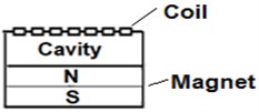
a) Vertical Polarization of B
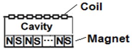
b) Horizontal Polarization of B
Fig. 3Magnitude curves of B above the speaker surface lying in the vertical planes along the center axes for different cavity height by using vertically and horizontally polarized magnets (diameter 3 mm)
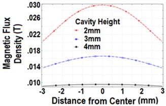
a) Vertically polarized magnets
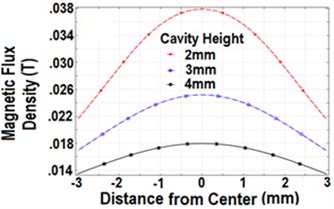
b) Horizontally polarized magnets
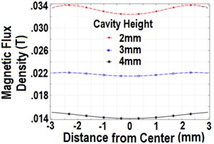
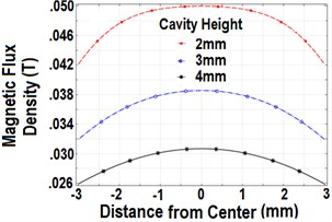
Considering the proposed structure of the FEPL the factors responsible for the performance includes the FEPL cavity height (i.e. the distance of the coil to the magnet), the magnet polarization and the magnet arrangement adopted. Let the diameter () of the magnet be 3 mm, and the cavity height is from 2 mm to 4 mm. For easy of presentation, Fig. 3 show the magnitude curves of magnetic flux densities (in one dimension) for different cavity heights by using vertically and horizontally polarized magnets, respectively. Note that as the cavity height increases, the magnetic flux densities decrease rapidly away from the center points for both vertically and horizontally polarized magnets. Moreover, if the diameter of the magnet is enlarged to 6 mm, Figs. 4(a) and 4(b) respectively show the measured magnetic flux densities by using the vertically and horizontally polarized magnets. Note the magnitudes of the magnetic flux densities are larger than those as shown in Figs. 3(a) and 3(b). Also note that as the cavity height increasing, the magnetic flux densities of both vertically and horizontally polarized magnet are decreased. But the distribution of the magnetic flux densities is very uniform over the surface of the diaphragm with the same height for the vertically polarized magnet. On the other hand, as the cavity height of the horizontally polarized magnet increases, the magnetic flux densities would be decrease rapidly at the locations moving farther away from the center point.
Thus one can predict the larger the size of speaker by using the vertically polarized magnet, the better the uniformity and sensitivity performance of SPLs. But this advantage may not be preserved by using the horizontally polarized magnet. The reason is that the distribution of the magnetic flux density would not be so uniform, which will exert unequal forces on the coils, and many modes of vibration can be easily excited.
Fig. 4Magnitude curves of B for different cavity height by using vertically and horizontally polarized magnets (diameter 6 mm)
a) Vertically polarized magnets
b) Horizontally polarized magnets
3. Results and discussions
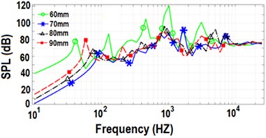
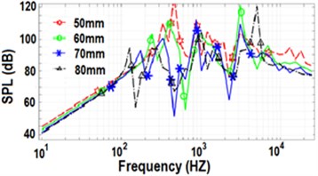
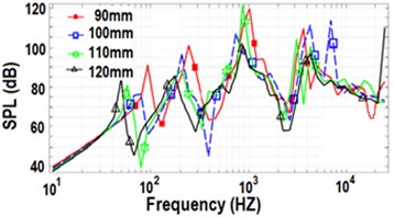
Firstly, the vertically polarized magnet with parameters shown in Fig. 5(a) is considered. A trade-off for the diaphragm dimension with 0.3 was studied. The simulation items are listed in Table 1 for reference, in which is defined as two times of the diameter, i.e. 2. Fig. 6 show the SPLs for Case 1 with 20 turns and 50-80 mm and 90-120 mm, respectively. Note that when is 60 mm (green), the overall performance of SPL is the best but with a large resonance peak at 750 Hz. The reason is that for this case the area of the diaphragm just covers the magnet, and which can raise the overall efficiency of speaker, while those SPLs of the other dimensions are not so good.
Fig. 5Structure and parameters of loudspeaker with vertically, and horizontally polarized magnets
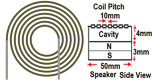
a) Vertically polarized magnets
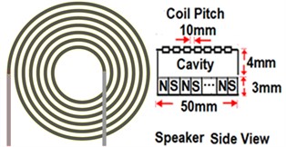
b) Horizontally polarized magnets
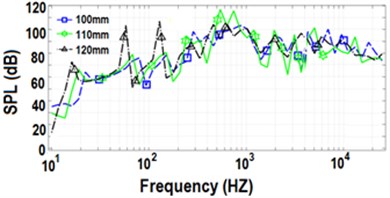
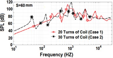
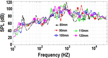
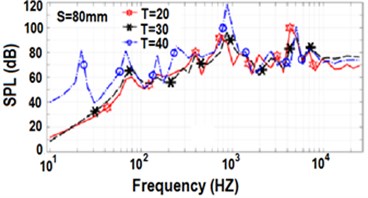
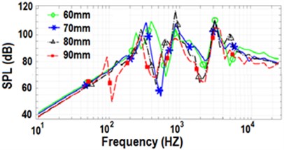
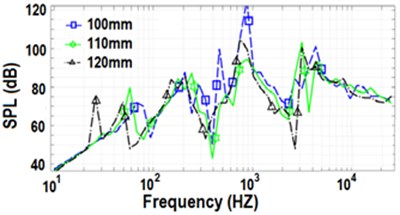
Fig. 7 show the SPLs for Case 2 with 30 turns and 60-90 mm and 100-120 mm, respectively. Note when is 60 mm (green), the overall performance of SPL is the best but with a large resonance peak at 1 KHz. The performance of SPL for 60 mm is even better than that of Case 1 in the range of lower frequency as shown in Fig. 8(a), because the value of (turns of coil) is larger for Case 2. The reason is similar to the previous Case 1 that for this condition the area of the diaphragm just covers the magnet, and then the overall efficiency would be the highest, while those SPLs of the other dimensions are not so good. Fig. 8(b) shows the SPLs for Case 3 with 40 turns of coil and 80-120 mm. Note when 80 mm (black), the overall performance of SPL is better and comparable to Case 2 (60 mm (green)) but with a large resonance peak at 900 Hz. The reason is similar to the previous Cases 1 and 2 that under this condition the area of the diaphragm is slightly larger than that of the magnet, and then the overall efficiency is better, while those of the others are not so good.
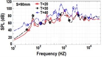
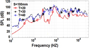
On the other hand, one can also compare the effect of the length . Fig. 9 show the SPLs for Cases 1-3 with to be 80, 90 and 100 mm, respectively. Note that the larger the magnitude of , then the magnitude of would also be increased and larger than that of the magnet, thus the overall efficiency would be better as shown in Fig. 9(b) (90 mm) and Fig. 9(c) (100 mm), respectively.
Table 1Simulation items with vertically polarized magnet
of diaphragm (mm) | 50 | 60 | 70 | 80 | 90 | 100 | 110 | 120 |
Turns of Coil (Case 1) | 20 | 20 | 20 | 20 | 20 | 20 | 20 | 20 |
Turns of Coil (Case 2) | * | 30 | 30 | 30 | 30 | 30 | 30 | 30 |
Turns of Coil (Case 3) | * | * | * | 40 | 40 | 40 | 40 | 40 |
*: not available | ||||||||
Fig. 6SPLs with vertically polarized magnet for Case 1
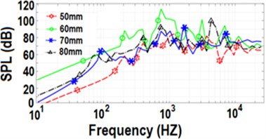
a)50-80 mm
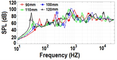
b)90-120 mm
Fig. 7SPLs with vertically polarized magnet for Case 2
a)60-90 mm
b)100-120 mm
Fig. 8Comparison of SPLs
a) Cases 1 and 2 for 60 mm
b) Case 3 with 80-120 mm
Now considering the SPL performances of horizontally polarized magnet, the structure and parameters of the speaker are shown in Fig. 5(b). The simulation items are listed in Table 2 for reference. Figs. 10(a) and 10(b) respectively show the SPLs of Case 1 (20 turns) for 50-80 mm and 90-120 mm. As predicted in previous paragraph although the SPLs are larger due to larger using horizontally polarized magnet, they may cause larger deviations in the frequency response of SPL. The reason is that the magnetic flux densities are quite different from each other at the coils as shown in Fig. 3(b) and 4(b), which would produce different forces and yield different modes of vibration, these modes of vibration may couple with each other, some of them may be in phase and some others out of phase, thus the performance of SPL may not good using horizontally polarized magnet.
Table 2Simulation items with horizontally polarized magnet
of diaphragm (mm) | 50 | 60 | 70 | 80 | 90 | 100 | 110 | 120 |
Turns of Coil (Case 4) | 50 | 50 | 50 | 50 | 50 | 50 | 50 | 50 |
Turns of Coil (Case 5) | * | 60 | 60 | 60 | 60 | 60 | 60 | 60 |
Turns of Coil (Case 6) | * | * | * | 80 | 80 | 80 | 80 | 80 |
*: not available | ||||||||
Fig. 9Comparison of SPLs for Cases 1-3
a)60 mm
b)90 mm
c)100 mm
Fig. 10SPLs with horizontally polarized magnet for Case 4
a)50-80 mm
b)90-120 mm
The next is to compare the performances for to be 30 and 40 turns of Cases 5 and 6, respectively. Figs. 11(a) and 11(b) respectively show the SPLs for Case 5 (30 turns) for 60-90 mm and 100-120 mm with horizontally polarized magnet. Fig. 12 shows the SPLs for Case 6 (40 turns) for 80-120 mm. There are still very large deviations in the frequency response of SPLs.
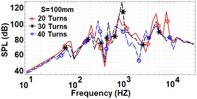
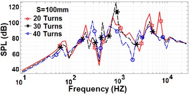
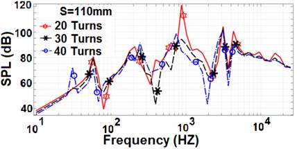
On the other hand, one can compare the performances for different turns of coil while using the same size of diaphragm, the results applying 60 and 70 mm with 20 and 30 turns are shown in Figs. 13(a) and 13(b), respectively. Moreover, the results applying 80, 90, 100, 110 and 120 mm with 20, 30 and 40 turns are also shown in Fig. 14. Note the major problem using the horizontally polarized magnet is that there are very large amount of deviations in the frequency responses of SPLs, which are independent on the size of diaphragms and turns of the coils as shown in Figs. 13 and 14.
The reason is that the magnitudes of magnetic flux density are unequal at the surfaces of diaphragms as previously described, so one should make the coils located near the center part of the diaphragm to reduce that modes of vibration and the cross-coupling effects.
Fig. 11SPLs with horizontally polarized magnet for Case 5
a)60-90 mm
b)100-120 mm
Fig. 12SPLs of Case 6 (T= 40 turns) for S= 80-120 mm and horizontally polarized magnet
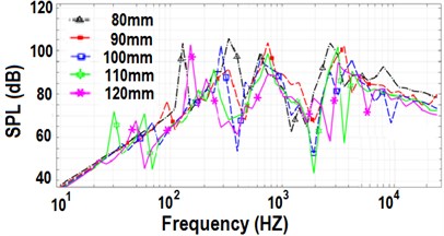
Fig. 13SPLs with horizontally polarized magnet for T= 20 and 30 turns
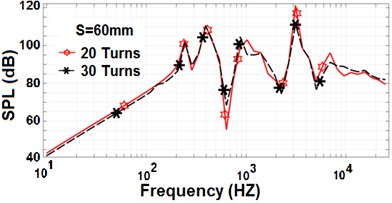
a)60 mm
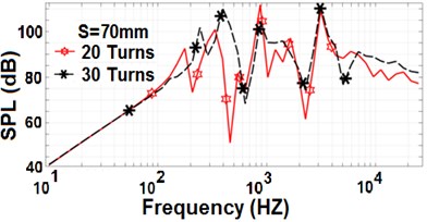
b)70 mm
4. Conclusions
This paper proposed a novel flexible electro-dynamic planar loudspeaker that can generate a good audible sound. Some factors of the structure and configuration that led to tradeoffs are also made, such as the thickness of the cavity, magnet and coil, magnet polarization, and diaphragm dimension. The FEPL has advantages over the traditional cone type speaker, e.g. its flexibility, simple structure, cost effectiveness, easy manufacturability and application versatility. The idea behind this study is a novel one, and as such has remained unexplored.
Fig. 14SPLs with horizontally polarized magnet for T= 20, 30, and 40 turns
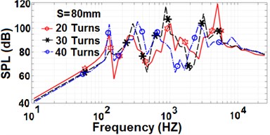
a)80 mm
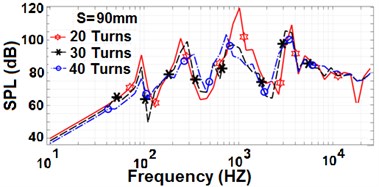
b)90 mm
c)100 mm
d)110 mm
e)120 mm
References
-
Suzuki M., Tsuzuki T., Komiyama T., Yamaguchi T., Furukawa T., Tokito S. Flexible colour OLED display based on phosphorescent material fabricated by ink-jet printing. Proceedings of 13th International Display Workshops, 2006, p. 3-6.
-
Fujisaki Y., Sato H., Yamamoto T., Fujikake H., Tokito S., Kurita T. Flexible color LCD panel driven by low-voltage-operation organic TFT. Journal of the Society for Information Display, Vol. 15, 2007, p. 501-506.
-
Takehiro S., Kazuho O., Akio A., Kohichi K., Akira H., Yuichi M., Akito M. PVDF-driven flexible and transparent loudspeaker. Applied Acoustics, Vol. 70, 2009, p. 1021-1028.
-
Rashedin R., Meydan T., Borza F. Electromagnetic micro-actuator array for loudspeaker application. Sensors and Actuators, Vol. 129, 2006, p. 118-120.
-
Lee C. S., Kim J. Y., Lee D. E., Joo J., Wagh B. G., Han S., Beag Y. W., Koh S. K. Flexible and transparent organic film speaker by using highly conducting PEDOT/PSS as electrode. Synthetic Metals, Vol. 139, 2003, p. 457-461.
-
Arved C. H., Maxi B., Georg C. S., Stefan Z., Andre G., Christian H. Fully mass printed loudspeakers on paper. Organic Electronics, Vol. 13, 2012, p. 2290-2295.
-
Lin J. M. Eletro-Acoustic Transducer and Method of Manufacturing the Same. U.S. Patent 2013/0163807 A1, 2013.
-
Fujifilm. http://www.diginfo.tv/v/13-0009-r-en.php.
-
Yamaha Develops Directional, Flat Panel Speakers – Video Inside. INAVATE, http://www.inavateonthenet.net, 2010.
-
SoundPad 580. Warwick Audio Technologies, http://www.warwickaudiotech.com/sites/default/ files/downloads.
-
Anthony C. ITRI Paper-Thin Flexible Loudspeaker Won Wall Street Journal’s Technology Innovation Awards. PRLog – Global Press Release Distribution, http://prlog.org/10365388, 2009.
-
Zhao Z. Planar Speaker System. US Patent 2013/0243238 A1, 2013.
-
Je S. S., Junseok C. An electromagnetically actuated micromachined loudspeaker for hearing aids applications. Sensors, IEEE, Atlanta, GA, 2007, p. 1024-1027.
-
Graebener D. Single End Planar Magnetic Speaker. U.S. Patent 7251342 B2, 2007.
-
Lemarquand G., Ravaud R., Shahosseini I., Lemarquand V., Moulin J., Lefeuvre E. MEMS electrodynamic loudspeakers for mobile phones. Applied Acoustics, Vol. 73, 2012, p. 379-385.
-
Shahosseini I., Lefeuvre E., Moulin J., Martincic E., Woytasik M., Pillonnet G., Lemarquand G. Planar microcoil optimization of MEMS electrodynamic microspeakers. IEEE Transaction on Magnetics, Vol. 49, 2013, p. 4843-4850.
-
Liou C. H., Chen M. D. Flexible Speaker. U.S. Patent 20090060249 A1, 2009.
-
Kontomichos F., Koutsioubas A., Mourjopoulos J., Spiliopoulos N., Vradis A. A thermoacoustic device for sound reproduction. Acoustics 2008 Paris, Paris, 2008.
-
Xiao L., Chen Z., Feng C., Liang L., Bai Z. Q., Wang Y., Qian L., Zhang Y., Li Q., Jiang K., Fan S. Flexible, stretchable, transparent carbon nanotube thin film loudspeakers. Nano Letters, Vol. 8, 2008, p. 4539-4545.
-
Mat D. Electronic Design. http://electronicdesign.com/boards/thin-speaker-technology, 2009.
-
“FLEXMAG” Arnold Magnetic Technologies. Arnold Magnetic Technologies Corporation, http://www.arnoldmagnetics.com, 2014.
-
Beranek L. L., Mellow T. J. Electrodynamic Loudspeakers. Acoustics: Sound Fields and Transducers. Academic Press, 2012, p. 241-288.
-
Loudspeaker Driver. COMSOL Muitiphysics, https://www.comsol.com/model/download/39132/ loudspeaker_driver, 2013
-
Daniel R. R. The Science and Applications of Acoustics. Second Edition, Springer Science Business Media Inc., 2006, p. 583.
About this article

