Abstract
In recently years, many sea-crossing bridges were built in some countries. For the complexity of seafloor condition and the stochastic characteristics of earthquakes, it is necessary to research the seismic responses of these sea-crossing bridges located on seawater layer and irregular bottom conditions. In this paper, a theory of the spatial varying ground motions was derived considering the wave propagation in soil and water. The effects of sea water layer, wave passage, coherence, local site and soil saturation on the seismic responses of a cable-stayed bridge were researched. The transfer function was used to calculate the local site effect and soil saturation effect. The seawater layer effect was studied via a simple medal from Crouse and Quilter. Multi-support and tri-direction excitations were utilized with large mass method. The seismic responses of a long span cable-stay bridge in the site conditions with and without seawater were compared. The results present that the seawater layer affects the earthquake response of bridge greatly, and the soil types have different effects on the different component of bridge. The research will help reasonably evaluate the security of sea-crossing bridge under earthquake excitation.
1. Introduction
In the coastal areas, many large span bridges were built crossing the sea such as Hong Kong-Zhuhai-Macao Bridge in China, Great Belt Bridge in Denmark, and Seto-Ohashi Bridge in Japan. For the reason that the soil distributed in coastal areas has many unfavorable site properties such as high water content, small shear strength and seawater layer, the site condition has significant impact on the propagation of earthquake ground motion [1-6]. Properly defining ground motions and reliable dynamic analysis are crucial for the security evaluation of the sea bridges locating on complex offshore sites.
To analyze the effects of local sites on the earthquake propagation, some researchers have proposed many theories and methods [7-9]. Bi and Hao [10] proposed a simple method to model spatially varying ground motions on the surface of non-uniform site conditions. This method takes the local site effect on motion amplification and spatial variation into consideration. Zhang et al. [11] developed a novelty method to simulating spatially varying ground motions, which can consider the local site effect, nonstationary, and compatibility of response spectra. These methods are limited to simulate ground motions. It is not suitable to consider the effects of soil saturation and seawater on ground motions. Wang and Hao [12] analyzed the effects of soil saturation variation on site amplification of earthquake ground motions using nonlinear wave propagation method. Li et al. [13] presented a theoretical modeling of seafloor seismic motions considering the effects of seawater layer and water saturation of soil layers on the propagation of ground motions. However, the soil types were not considered in the parameters of power spectral density.
In practical engineering applications, some researchers studied the effects of spatial varying ground motions on long span bridge. Jia et al. [14] proposed a theoretical approach to study the local site effects on a bridge under tri-directional spatial excitations. Karmakar et al. [15] discussed the seismic response of retrofitted Vincent Thomas Bridge under generated spectrum-compatible spatially variable earthquake waves. Soyluk and Sicacik [16] researched the responses of cable-stayed bridge for spatially varying ground motions through simulating ground motion time histories including the incoherence, wave-passage and site-response effects. An experimental of joint earthquake, wave current action on the pile group cable-stayed bridge tower was studied by Liu et al. [17]. These researches focused on the effects of the spatial variability of ground motion at support points of long-span bridge. The results propose guidance for the design of long-span bridges built on land site. Several past studies concerning sea-bridges focused on the effects of spatial variability of ground motions using onshore earthquake recordings. The effect of seawater layer on earthquake motions was neglected due to the lack of seafloor seismic recordings. This may lead to erroneous safety assessments since the difference between the seafloor earthquake motions and the onshore ground motions.
In order to investigate the seismic response of long span cable-stayed bridge built on seafloor, a simulate theory of spatial varying seafloor motion was proposed. The soil saturation and seawater effect on the spatial varying ground motions were considered in the proposed model except the wave passage effect, partial coherency effect, and local site effect. A 3D finite element model of a long span cable-stayed bridge was built using ANSYS software. The nonstationary response of the bridge model under multi-support and tri-dimensional earthquake excitations was presented. Two soil types, firm soil and soft soil, were considered. The bridge seismic responses were divided into two groups, a site without seawater group and a site with seawater group. The seismic response of the cable-stayed bridge, include displacement, bending moment and structure force of different axis directions, were discussed.
2. Theoretical basis
2.1. Wave propagation theory
For a site with horizontally extended soil layer on a half space, the ground motions are usually assumed to consisting of out-of-plane SH wave and in-plane combined P-SV waves. The SH wave motions propagate in the horizontal direction and P-SV waves motions in the transverse and vertical directions. Based on the theory of one-dimensional wave propagation [18], the dynamic equilibrium equations can be written as:
where, and are the wave velocities of wave and wave, respectively; and are Laplace operators acting on volumetric strain e and rotational strain vector , respectively.
In the frequency domain, the dynamic equations can be expressed as:
In which, and are displacement matrix and load vector of SH wave, respectively; and are displacement matrix and load vector of combined P-SV waves; and are the stiffness matrices, respectively.
2.2. Site amplification effect
2.2.1. Site transfer function
The effect of site amplification is usually estimated with the site transfer function . The relationship of amplitudes between base rock and each soil layer can be formed by follow equations [19].
For a site consisting of a single homogeneous layer on a half-space, assembling stiffness matrices, displacements and load vectors of SH wave can be expressed as:
where, is wave number, is a parameter related to incident angle, is the shear modulus, is the depth of soil layer, and are the displacements at the top and bottom of soil layer, respectively; is imaginary component, means transpose; superscript , and * represent base rock, soil layer and hysteresis, respectively.
As above formulas shown, the site transfer function of SH wave can be written as:
In which is the impedance ratio. And the site transfer function of P-SV wave also can be calculated in the same way.
2.2.2. Seawater layer effect
A simple model was developed by Crouse and Quilter based on the assumption that the vertical component of ground motion was only composed of vertically propagating wave [2]. For the seafloor site, the wave can transmit through the seawater layer, and reflect back towards the seafloor. a phase change will result in the reduction in the amplitude of vertical ground motion at the natural frequency of seawater layer. The modulus that describes the response of seafloor site with seawater layer is given as follows:
where, is the frequency, is the height of seawater layer, is the impedance ratio between seawater layer and seafloor soil, in which, and are the wave velocity in seawater and seafloor site, respectively; is density, and the subscript 1 and 2 are seawater layer and seafloor site, respectively.
It is evident that 1. is the bulk modulus of seawater; , in which, is Lame constant, is the shear modulus of seafloor site.
In this paper, the damping of seafloor site and fluid were considered, the complex values of bulk modulus of seawater and shear modulus of seafloor site are expressed as:
where is the damping coefficient, is imaginary part. Therefore, the modulus of seawater transfer function is given as follows:
In which, is the complex values of wave velocity in seawater.
2.2.3. Soil saturation effect
In consideration of soil saturation effect on site amplification, the parameters of water saturation, wave velocity, Poisson’s ratio, and so on, were introduced in references [20-22]. They are expressed as:
In which, is the degree of water saturation, is wave velocity, is Lame constant of soil skeleton, is shear modulus of soil skeleton and is Poisson’s ratio:
where is Poisson’s ratio of soil skeleton, , and are the bulk moduli of water, solid grains and skeleton, is bulk modulus of homogeneous fluid, is absolute fluid pressure, is porosity, , and are the volumes of pores, pore water and total volume, respectively.
Substituting the results of Eqs. (9-10) into site transfer function, the effect of soil saturation level on ground motion amplification can be estimated.
2.3. Ground motion generation
The coherency of acceleration time history for a pairs of stations (, ) is defined as:
where is the coherency function between stations and , and are the auto-power spectral densities of station and , respectively; and is the cross-power spectrum density. The coherency is a complex valued quantity [23, 24], thus Eq. (13) can be written as:
The cross power spectral density function of ground motions is:
In which, and are the auto and cross power spectral density functions, respectively; is the matrix of power spectral density function; and are site transfer functions at location and on the ground surface, respectively; and superscript means conjugate transpose.
Decomposing the Hermitian of positive definite matrix into lower triangular matrix and its Hermitian matrix using the Cholesky method:
The stationary time series can be expressed as:
In which, are the random phase angles which are uniformly distributed over the range of [0, 2], and represents an upper cut-off frequency [25].
If the Jennings envelope function is adopted to simulate the non-stationary time series, which is given as follows:
2.4. The theory of multi-support excitation
First we derived the structural dynamic equation of multi-support excitation using the large mass method [14]. The dynamic equation as follow:
In which, [], [] and [] are the mass, damping and stiffness matrices, respectively, {}, {} and {} are the acceleration, velocity and displacement vectors. The subscripts and refer to the structure and base, and subscripts , and denote the degrees of freedom (DOF) of structural, base and coupled, respectively. {} is the ground motion acceleration.
The Eq. (20) can be expressed as:
Assuming the values of {} are very large. Then if Eq. (22) is divided by {} both sides, one obtains:
The lumped mass was used in finite element analysis, then, {} = 0. Substituting Eq. (23) into Eq. (21):
The Eq. (24) is the large mass method that has been used in finite element analysis under multiple earthquake excitations. Usually the range of values for large mass {} is 105 to 108.
3. Numerical examples
3.1. Finite element modeling
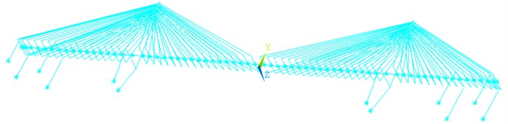
To study seawater layer effects on the dynamic response of a sea-crossing bridge under tri-directional spatial ground motions, the seismic analysis of a large span cable-stayed bridge was conducted using the generated multi-point artificial waves [26-28]. The bridge has five spans; the main span of 436 m, first side spans of 126 m and second side spans of 60 m. The height of left towel of bridge is 167.19 m, its pier has height of 55.73 m; the height of right towel is 172.69 m, its pier has height of 61.23 m. A 3D finite element model of the cable-stayed bridge was developed using ANSYS software, as shown in Fig. 1. The beam4 type element was used to model main girders and piers. The link8 type element was adopted to simulate the cable. The mass21 type element was used to model the added mass and the large mass in large mass method. The bottom of all piers were defined as the boundary conditions. is the longitudinal direction of the cable-stayed bridge, is the vertical direction, and is the transverse direction.
Fig. 1Finite element modeling of cable-stayed bridge
3.2. Site conditions
To analyze the effects of seawater layer on the responses of cable-stayed bridge under earthquake excitation, four cases with different site conditions were designed in this paper: firm soil, soft soil, firm soil with seawater layer and soft soil with seawater layer. The properties of soil are presented in Table 1, and is the layer depth, is the shear modulus, is the density, is the damping ratio and is the Poisson ratio, respectively. The height of seawater layer is 20 m.
Table 1Properties of different sites and base rock
Soil type | (m) | (MPa) | (kN/m3) | ||
Firm soil | 33 | 120 | 19 | 0.35 | 0.05 |
Soft soil | 33 | 30 | 16 | 0.38 | 0.05 |
Base rock | – | 1567.3 | 29 | 0.3 | 0.05 |
3.3. Simulation of spatially ground motions
In this example, the coherency loss of ground motions at different piers can be estimated by empirical coherency function. The Harichandran-Vanmarcke model [29] is selected, which has the following formula:
where is the lagged coherency loss, is the spatial distance. In the calculation example, 0.626, 0.022, 19700 m, 12.692, and 3.47.
The power spectral density (PSD) of the ground motion on the base rock is modelled by the Clough-Penzien [30], which has an expression as:
where and are the central frequency and the damping ratio of low pass filter, respectively; and are the central frequency and the damping ratio of high pass filter, respectively; is a scaling factor depending on ground motion intensity.
The parameters of Clough-Penzien model for the firm soil and soft soil conditions are summarized as the values proposed by Yeh and Wen [31], Monti et al. [32], Der Kiureghian and Neuenhofer [33], Marano et al. [34]; the better fit values of this paper are calculated in Table 2.
Table 2Parameters of power spectral density for different soil types
Soil type | (rad/s) | (rad/s) | ||
Firm soil | 15 | 0.65 | 1.5 | 0.6 |
Soft soil | 4.5 | 0.2 | 0.3 | 0.5 |
To model the simulated non-stationary time histories, the stationary time histories are multiplied by the Jennings envelope function, which has the following form:
In which, 1 s and 15 s.
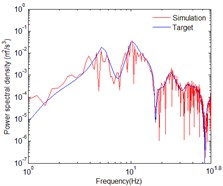
The images below show the three-dimensional orthogonal acceleration time histories and power spectral density at the bottom of the right bridge tower. The axis is horizontal out-of-plane motion, axis is vertical in-plane motion, and axis is horizontal in-plane motion. The incident angles of out-of-plane SH wave and in-plane P-SV wave was assumed to be 60°. The water saturation of seafloor soil has a significant effect to the amplification of P-SV wave, and few effects on the SH wave. The vertical in-plane motion is dominated by wave, thus the seawater layer has a huge impact on the acceleration time histories of vertical in-plane motion. So, the acceleration time histories of horizontal out-of-plane motion are not affected by seawater layer and soil saturation as shown in Fig. 2. The acceleration time histories shown in Fig. 2, Fig. 4 and Fig. 8 only considered the effects of wave passage, coherence and local site. Compared with Fig. 4, the effect of soil saturation is considered in the acceleration time histories shown in Fig. 6. Compared with the acceleration time histories shown in Fig. 8, the time histories shown in Fig. 10 considered the effects of seawater layer and soil saturation.
Fig. 2The acceleration time histories of horizontal out-of-plane motion
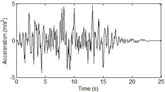
Fig. 3Comparison of PSDs for horizontal out-of-plane motion
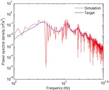
Fig. 4The acceleration time histories of horizontal in-plane motion
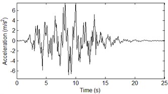
Fig. 5Comparison of PSDs for horizontal in-plane motion
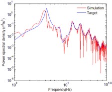
Fig. 6The acceleration time histories of horizontal in-plane motion with seawater
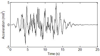
Fig. 7Comparison of PSDs for horizontal in-plane motion with seawater
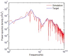
Fig. 8The acceleration time histories of vertical in-plane motion
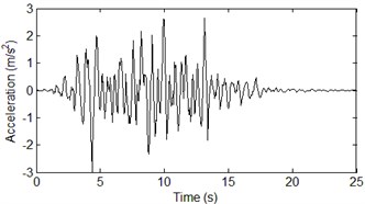
Fig. 9Comparison of PSDs for vertical in-plane motion
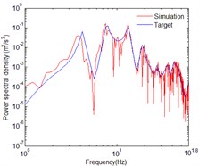
Fig. 10The acceleration time histories of vertical in-plane motion with seawater
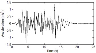
Fig. 11Comparison of PSDs for vertical in-plane motion with seawater
4. Numerical results
This research focused on the effects of seawater layer on bridge dynamic responses considering different soil types and seawater. The comparisons of the seismic response characteristics without seawater and with seawater on the bridge were studied, which were more concerned by designers and engineers in the operating period of cable-stayed bridges.
As shown in Figs. 12-13, whether firm soil or soft soil, the absolute maximum of vertical displacements of bridge deck with seawater are smaller than that without seawater. After considering the seawater effects, the peak displacements decline 22 % and 35 % with firm soil and soft soil, respectively. And the reason of asymmetry decreasing of vertical displacement is that the towers and piers on the two sides of bridge are slightly different.
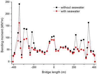
The absolute maximum bending moments of bridge deck at transverse direction are show in Figs. 14, 15, and the peak bending moments are decrease by 10 % and 33 % with firm soil and soft soil, respectively.
Fig. 12Absolute maximum Y-displacements of bridge deck with firm soil
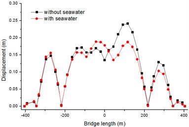
Fig. 13Absolute maximum Y-displacements of bridge deck with soft soil
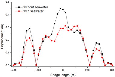
Fig. 14Absolute maximum Z-bending moments of bridge deck with firm soil
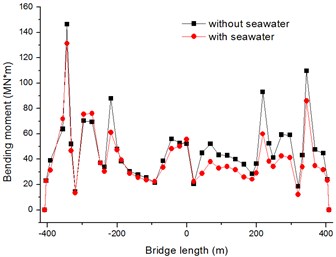
Fig. 15Absolute maximum Z-bending moments of bridge deck with soft soil
In Figs. 16, 17, the seawater has few effects on the response of the longitudinal direction displacements of bridge tower. The reason is that the acceleration time histories in longitudinal direction is belong to horizontal out-of-plane motion which is slightly affected by seawater and soil saturation. In Figs. 18, 19, it is obvious that the transverse displacements of tower top are attenuate greatly due to the seawater effect, the peak displacements decline 48 % and 11 % with firm soil and soft soil, respectively.
As Figs. 20, 21 shown, the seawater has a big effect on the longitudinal bending moments of tower bottom. And the peak bending moments are decrease by 47 % and 19 % with firm soil and soft soil, respectively. However, the transverse bending moments of bridge tower are no change with seawater in Figs. 22, 23.
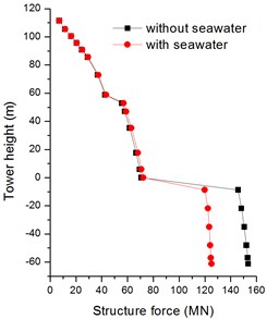
In Figs. 24, 25, the vertical internal forces of bridge tower are greatly affected by seawater with firm soil, and slightly affect by seawater with soft soil. The peak structure forces are decrease by 26 % and 3 % with firm soil and soft soil, respectively. Fig. 26 shows the absolute maximum transverse internal forces with firm soil are changed at the whole bridge tower; while the structure forces with soft soil are only changed at the bottom of bridge tower in Fig. 27. The peak structure forces in transverse direction decline 34 % and 19 % with firm soil and soft soil.
Fig. 16Absolute maximum X-displacements of bridge tower with firm soil
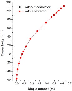
Fig. 17Absolute maximum X-displacements of bridge tower with soft soil
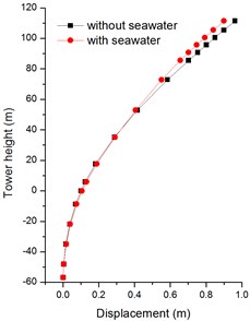
Fig. 18Absolute maximum Z-displacements of bridge tower with firm soil
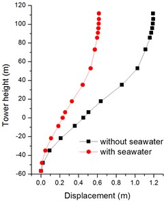
Fig. 19Absolute maximum Z-displacements of bridge tower with soft soil
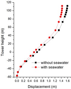
Fig. 20Absolute maximum X-bending moments of bridge tower with firm soil
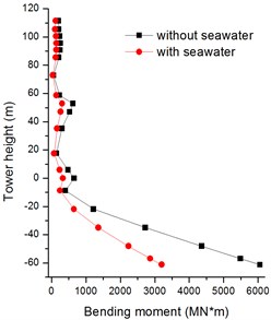
Fig. 21Absolute maximum X-bending moments of bridge tower with soft soil
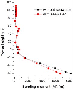
Fig. 22Absolute maximum Z-bending moments of bridge tower with firm soil
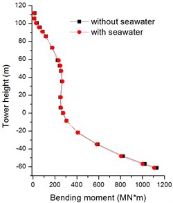
Fig. 23Absolute maximum Z-bending moments of bridge tower with soft soil
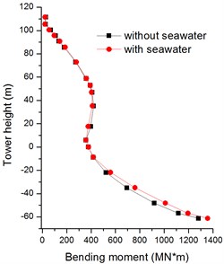
Fig. 24Absolute maximum Y-structure forces of bridge tower with firm soil
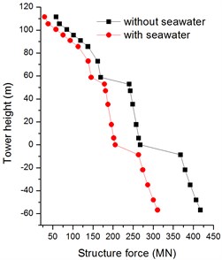
Fig. 25Absolute maximum Y-structure forces of bridge tower with soft soil
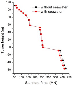
Fig. 26Absolute maximum Z-structure forces of bridge tower with firm soil
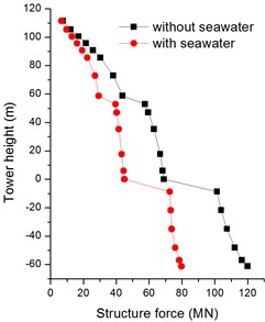
Fig. 27Absolute maximum Z-structure forces of bridge tower with soft soil
5. Conclusions
This research focused on the effects of seawater layer on bridge dynamic responses considering different soil types and seawater. The acceleration time histories of tri-directional spatial varying ground motions were generated using a new method. The large mass method was utilized as the multi-support excitation method to compute the dynamic response of a long cable-stayed bridge locating on seafloor. The seismic responses considering wave passage, partial coherence, local site, soil saturation and seawater, were analyzed. The conclusions were drawn as followings:
1) The horizontal in-plane and vertical in-plane ground motions are strongly affect by the seawater and soil saturation. The acceleration time histories of the seafloor motions in vertical direction are weaker than those of onshore motions, while the peak accelerations in out-plane horizontal direction are similar.
2) The dynamic responses of long span cable-stay bridge excited by seafloor seismic motions and onshore motions are significantly different. The corresponding axis direction values of displacement, bending moment and structure force can be attenuated obviously by seawater and soil saturation. The changes of longitudinal displacements and transverse bending moments of bridge tower are minor. For the results of vertical displacements and transverse bending moments of bridge deck, the responses with soft soil are much larger than that with firm soil. The effects of seawater layer on structural response should be considered carefully.
References
-
Boore D. M., Smith C. E. Analysis of earthquake recordings obtained from the seafloor earthquake measurement system (SEMS) instruments deployed off the coast of southern California. Bulletin of the Seismological Society of America, Vol. 89, Issue 1, 1999, p. 260-274.
-
Diao H., Hu J., Xie L. Effect of seawater on incident plane P and SV waves at ocean bottom and engineering characteristics of offshore ground motion records off the coast of southern California, USA. Earthquake Engineering and Engineering Vibration, Vol. 13, Issue 2, 2014, p. 181-194.
-
Konakli K., Der Kiureghian A. Simulation of spatially varying ground motions including incoherence, wave-passage and differential site-response effects. Earthquake Engineering and Structural Dynamics, Vol. 41, Issue 3, 2012, p. 495-513.
-
Petukhin A., Iwata T., Kagawa T. Study on the effect of the oceanic water layer on strong ground motion simulations. Earth, Planets and Space, Vol. 62, Issue 8, 2010, p. 621-630.
-
Zhang D., Xie W., Pandey M. D. Synthesis of spatially correlated ground motions at varying sites based on vector-valued seismic hazard deaggregation. Soil Dynamics and Earthquake Engineering, Vol. 41, 2012, p. 1-13.
-
Hatayama K. Theoretical evaluation of effects of sea on seismic ground motion. 13th World Conference on Earthquake Engineering, Vancouver, Canada, 2004.
-
Zhang D., Jia H., Zheng S., Xie W., Pandey M. D. A highly efficient and accurate stochastic seismic analysis approach for structures under tridirectional nonstationary multiple excitations. Computers and Structures, Vol. 145, 2014, p. 23-35.
-
Soyluk K. Comparison of random vibration methods for multi-support seismic excitation analysis of long-span bridges. Engineering Structures, Vol. 26, Issue 11, 2004, p. 1573-1583.
-
Bi K., Hao H. Numerical simulation of pounding damage to bridge structures under spatially varying ground motions. Engineering Structures, Vol. 46, 2013, p. 62-76.
-
Bi K., Hao H. Modelling and simulation of spatially varying earthquake ground motions at sites with varying conditions. Probabilistic Engineering Mechanics, Vol. 29, 2012, p. 92-104.
-
Zhang D., Liu W., Xie W., Pandey M. D. Modeling of spatially correlated, site-reflected, and nonstationary ground motions compatible with response spectrum. Soil Dynamics and Earthquake Engineering, Vol. 55, 2013, p. 21-32.
-
Wang S., Hao H. Effects of random variations of soil properties on site amplification of seismic ground motions. Soil Dynamics and Earthquake Engineering, Vol. 22, 2002, p. 551-564.
-
Li C., Hao H., Li H., Bi K. Theoretical modeling and numerical simulation of seismic motions at seafloor. Soil Dynamics and Earthquake Engineering, Vol. 77, 2015, p. 220-225.
-
Jia H., Zhang D., Zheng S., Xie W., Pandey M. D. Local site effects on a high-pier railway bridge under tridirectional spatial excitations: nonstationary stochastic analysis. Soil Dynamics and Earthquake Engineering, Vol. 52, 2013, p. 55-69.
-
Karmakar D., Ray Chaudhuri S., Shinozuka M. Seismic response evaluation of retrofitted Vincent Thomas bridge under spatially variable ground motions. Soil Dynamics and Earthquake Engineering, Vol. 42, 2012, p. 119-127.
-
Soyluk K., Sicacik E. A. Soil-structure interaction analysis of cable-stayed bridges for spatially varying ground motion components. Soil Dynamics and Earthquake Engineering, Vol. 35, 2012, p. 80-90.
-
Liu C., Zhang S., Hao E. Joint earthquake, wave and current action on the pile group cable-stayed bridge tower foundation: an experimental study. Applied Ocean Research, Vol. 63, 2017, p. 157-169.
-
Bi K., Hao H. Influence of irregular topography and random soil properties on coherency loss of spatial seismic ground motions. Earthquake Engineering and Structural Dynamics, Vol. 40, Issue 9, 2011, p. 1045-1061.
-
Pan D. Seismic Response Analysis of Soil Layer on Complex Sites. Tongji University, Shanghai, 2003.
-
Yang J., Sato T. Influence of water saturation on horizontal and vertical motion at a porous soil interface induced by incident SV wave. Soil Dynamics and Earthquake Engineering, Vol. 19, 2000, p. 339-346.
-
Yang J. Saturation effects of soils on ground motion at free surface due to incident SV waves. Journal of Engineering Mechanics, Vol. 128, Issue 12, 2002, p. 1295-1303.
-
Yang J. Saturation effects on horizontal and vertical motions in a layered soil-bedrock system due to inclined SV waves. Soil Dynamics and Earthquake Engineering, Vol. 21, 2001, p. 527-536.
-
Ding H., Trifunac M. D., Todorovska M. I., Orbović N. Coherence of dispersed synthetic strong earthquake ground motion at small separation distances. Soil Dynamics and Earthquake Engineering, Vol. 70, 2015, p. 1-10.
-
Yu R. F., Abduwaris A., Yuan M. Q., Yu Y. X. Coherency function model of seismic ground motion based on accelerograms recorded by zigong seismograph array. International Efforts in Lifeline Earthquake Engineering, 2014, p. 529-536.
-
Gao Y., Wu Y., Li D., Liu H., Zhang N. An improved approximation for the spectral representation method in the simulation of spatially varying ground motions. Probabilistic Engineering Mechanics, Vol. 29, 2012, p. 7-15.
-
Dumanogluid A. A., Soyluk K. A stochastic analysis of long span structures subjected to spatially varying ground motions including the site-response effect. Engineering Structures, Vol. 25, Issue 10, 2003, p. 1301-1310.
-
Memisoglu Apaydın N. Earthquake performance assessment and retrofit investigations of two suspension bridges in Istanbul. Soil Dynamics and Earthquake Engineering, Vol. 30, Issue 8, 2010, p. 702-710.
-
Apaydin N. M., Bas S., Harmandar E. Response of the Fatih Sultan Mehmet Suspension Bridge under spatially varying multi-point earthquake excitations. Soil Dynamics and Earthquake Engineering, Vol. 84, 2016, p. 44-54.
-
Harichandran R. S., et al. Stochastic variation of earthquake ground motion in space and time. Journal of Engineering Mechanics, Vol. 112, Issue 2, 1986, p. 154-174.
-
Clough R., Penzien J. Dynamics of Structures. McGraw Hill, New York, 1993.
-
Yeh C.-H., Wen Y. K. Modeling of nonstationary ground motion and analysis of inelastic structural response. Structure Safety, Vol. 8, 1990, p. 281-298.
-
Monti G., Nuti C., Pinto Pe, Vanzi I. Effects of nonsynchronous seismic input on the inelastic response of bridges. II International Workshop on Seismic Design of Bridges, Queenstown, NewZealand, 1994.
-
Kiureghian A. D., Neuenhofer A. Response spectrum method for multisupport seismic excitations. Earthquake Engineering and Structural Dynamics, Vol. 21, 1992, p. 713-740.
-
Marano G. C., Trentadue F., Morrone E., Amara L. Sensitivity analysis of optimum stochastic nonstationary response spectra under uncertain soil parameters. Soil Dynamics and Earthquake Engineering, Vol. 28, Issue 12, 2008, p. 1078-1093.
About this article

This work was partially supported by the Major State Basic Research Development Program of China (973 Program, grant number 2015CB057704), the Natural Science Foundation of China (grant number 51678110). The authors would like to thank for them for their financial support.
