Abstract
This paper deals with the dynamic stability of a rigid rotor arbitrarily filled with liquid. On the basis of the established coupled-field equations of the rotor system, the general whirling eigenequation, which is a quartic complex coefficients equation, is derived. In order to obtain the solutions of the general whirling eigenequation, a mathematical method is proposed. To illustrate the precision of calculating results, a comparison is carried out between the present analysis and the numerical results. The results show that two calculation results are in good agreement. Then the stability of the rotor system is analyzed. It is shown that the dynamic instability occurs at a particular bound of the spinning speed. Moreover, the effects of system parameters, such as fluid-fill ratio and mass ratio, on the unstable regions are discussed.
Highlights
- A mathematical method for obtaining the solutions of the general whirling eigen-equation was proposed.
- The whirling frequency equation of the rigid liquid-filled rotor was presented to predict the system stability.
- The dynamic instability occurs at a particular bound of the spinning speed.
- The effects of some main parameters on system stability were discussed.
1. Introduction
Rotor filled with liquid is applied widely in engineering. The inside of rotor is hollow, and the chamber contains liquid. When the rotating cylinder suffers the perturbation in working, the whirling motion occurs. An additional pressure, which acts on rotating cylinder internal surface, results from the relative rotation between liquid and rotor. This forms a complex fluid-solid coupling problems. Meanwhile, due to the interaction between rotating fluid and rotor, the phenomenon of rotor system instability happens at a certain RPM range. Therefore, it has very important significance to study dynamic stability of rotor filled with liquid.
The dynamic stability of rotor filled with liquid was first studied by Kollmann, Jlnnouchi, and Crandall [1-4]. The critical speed of Jeffcott single-disc rotor filled with liquid was calculated by Kollmann. The instability phenomenon was observed on the rotor partially filled with liquid in the experiment. Crandall analyzed the dynamic stability of a flexible rotor filled with liquid. After that, the dynamic characteristics of parallel whirling motion were analyzed for rotor filled with liquid by Wolf [5]. In the early study, the liquid of rotor chamber was assumed to be ideal and rotor body was rigid. For this reason, the dynamic stability was investigated for rotor filled with viscous liquid by Hendricks, Daich and Bar, Saito and Holm-Christensen [6-9]. Furthermore, rigid body angular displacement was introduced by Hendricks and Lichtenberg, the research on rotor filled with liquid was extended to three dimensions [10, 11]. Hiroshi Ota et al. made experiments on the vibration of rotor filled with liquid, the effect of viscosity and specific gravity on the unstable vibration were studied simultaneously [12]. Yuichi SATO proposed a dynamic absorber using a hollow rotor partially filled with liquid, a kind of technique was described to suppress structure vibration, and the effectiveness of proposed absorber was showed experimentally [13].Kuipers analyzed the stability of a flexibly mounted rotating cylinder partially filled with liquid. The rotor was assumed to rotate around its axis of symmetry with a constant angular velocity and the liquid was ideal in the chamber. The unstable region was derived and the effect of combined action of dissipative and gyroscopic terms was researched by him [14]. Zhang et al. further discussed the dynamic stability of rigid and flexible rotor filled with liquid [15].
In recent years, there are many related researches on the stability of rotor filled with liquid. The experimental investigation was made on the dynamic characteristics of an over-hung rigid centrifuge rotor partially filled with liquid by Zhu [16].The influence of fluid-fill ratio on rotor whirl frequency, the range of unstable region, and the rotor imbalance were researched. Furtherly, the stability of rotor filled with viscous incompressible fluid was analyzed by him. The dynamic stability was investigated on flexible rotating cylinder partially filled with liquid by Tao and Zhang, they proposed that the three dimensional flow can be simplified to two dimensional flow problem in the chamber [17]. Yukio Ishida et al. applied a method, which utilizes discontinuous spring characteristics, to suppress unstable vibrations in an asymmetrical rotor system, an asymmetrical shaft system, and a rotor system partially filled with liquid [18].N. V. Derendyaev et al. investigated the stability of a cylinder filled with different kinds of liquid, including viscous incompressible liquid, a stratified viscous incompressible liquid and a stratified non-uniform viscous incompressible liquid [19-22]. In 1988, Derendyaev proved that Andronov-Hopf bifurcations may occur in a rotor system filled with liquid [23]. In his work, the methodological mistakes made by Wolf Jr. et al. were analyzed [24].
Many researchers have investigated the vibration and fault diagnosis for a rotor system, but little information is available on the analytical solutions of the general whirling eigenequation [25-33]. In this paper, considering the complex form of the equation, a mathematical analysis method is proposed to obtain the solutions of the general whirling eigenequation. The effective of the method is verified by comparing with numerical method. Then, according to whirling eigenequation, the dynamic stability of a liquid-filled rotor system is analyzed, and the effects of fluid-fill ratio and mass ratio on unstable region and critical speed of rotor system are discussed.
2. General whirling eigenequation
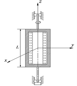
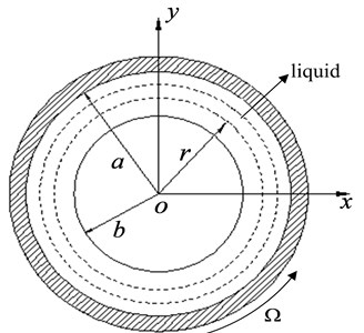
The structure of rotor filled with liquid is shown in Fig. 1. Rotor is a hollow cylinder, the length of cylinder is , inner diameter is , mass is , centroid is . The liquid is filled in cylinder chamber, both ends of rotor are supported on bearings symmetrically through two flexible shafts, the distance between rotating shaft and liquid level is . Static coordinate - is established based on the axis of rotor under static state. When rotor rotates at an angular velocity , the rotation is assumed to be steady and unperturbed, rotor and liquid rotate synchronously, rotor axis coincides with liquid centroid , as shown in Fig. 1(b).
Fig. 1Structure of rotor filled with liquid
a)
b)
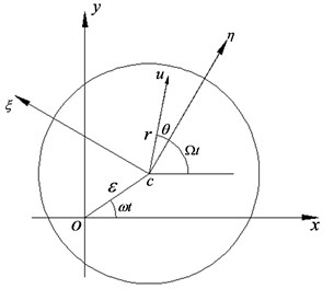
When rotor suffers perturbation in working, whirling motion is formed in chamber. We assume that the radial deviation of axis is , rotor whirling frequency is . Here, liquid centroid and rotor axis do not coincide with each other, rotor of centroid rotates with angular velocity , which is shown in Fig. 2.
It is assumed that the liquid is ideal; in addition, and are relative perturbation displacements of the centroid in the direction of and . Then, the whirling kinetic equation of rotor centroid can be written as follows:
where is external damping coefficient, is elastic support stiffness, and are force caused by fluid acts on the rotor, is self-rotation angular velocity.
Fig. 2Parallel whirling of a rotor filled with liquid
Based on fluid mechanics, Euler's equation of fluid in rotor chamber can be expressed as:
where the parameter is given by:
where is perturbation pressure, and are components of centroid absolute acceleration along the direction of and .
The continuity equation of fluid in rotor chamber can be written as:
For solving the fluid-solid coupling equation of rotor whirling motion above, first and foremost, boundary conditions should be determined. We assume that fluid free surface is , here is perturbation infinitesimal displacement. Then boundary condition of fluid free surface can be represented as:
and fluid displacement boundary condition takes the form:
Based on Eqs. (1), (2) and (4), external damping coefficient is neglected, we can derive the general whirling motion eigenequation for rigid rotor arbitrarily filled with liquid by using boundary conditions Eqs. (5) and (6). The eigenequation is as follows:
where , and are defined as:
where is the liquid mass, is the nature frequency of a solid rotor. Then, we can expand Eq. (7) as follows:
where and can be shown as:
3. Analytical solution for general whirling eigenequation
3.1. Solution procedure
Dynamic stability of rotor arbitrary filled with liquid is a quite complex problem. Furthermore, the general whirling eigenequation is a quartic complex coefficients equation. In order to investigate rotor dynamic stability, the eigenequation needs to be analyzed further. To this end, derivational process for the analytical solution of the eigenequation is given as below.
Eq. (8) takes the form:
Let , , and , Eq. (9) can be written in the simplified form:
We assume that , , and are four unknown roots of Eq. (10), let , , and , Eq. (10) can be written as:
Then, Eq. (11) can be expanded as follows:
Let us suppose that eigenequation has two conjugate complex roots, or two real roots. There is an independent complex root inevitably among the others. Therefore, if and are real numbers, and become complex numbers certainly.
Let and , because Eq. (12) is equal to Eq. (10), the coefficients of two equations should be equal. According to complex number algebra, the relationships of coefficients real part for two equations are given by:
In addition, we introduce an unknown quantity , which gives that:
Substituting Eq. (17) into Eq. (14), we obtain:
By Eq. (14) and Eq. (16), we can derive:
Then we can square both sides of Eq. (15):
For eliminating , , and , the Eq. (19) and Eq. (20) are added:
Square both sides of Eq. (13), and multiply by , we have:
Adding to Eq. (19), then we get:
Add Eq. (21) to get:
Here, removing , by Eq. (13) and Eq. (15), we obtain:
Both sides are multiplied by , then the Eq. (25) becomes:
Subtract Eq. (24) to get:
Both sides of Eq. (18) are multiplied by so that:
Add Eq. (27) to get:
Eq. (29) can be solved and the roots take the form:
where:
Then, and can be determined from Eq. (16) and Eq. (17), respectively:
and are solved by Eq. (13), Eq. (14) and Eq. (17), respectively:
The values of , , , should satisfy Eq. (15). According to the values of , we can have a discussion as follows.
Case 1:
In this case, two sets of values are obtained, respectively:
and:
Case 2:
In this condition, we get:
and:
Case 3:
If takes this value, accordingly, the values of , , , take the form:
Due to 0, such situation does not exist. Only case 1 and case 2 are logical.
Now let us consider the imaginary parts of and . From Eq. (14), Eq. (15) and Eq. (16), we obtain:
Because , , , can’t all be real, 0, it follows that:
In conclusion, , , , can be solved, we have:
where:
The roots of Eq. (8) take the form:
Finally, substituting the values for , , , into Eq. (31), four roots of Eq. (8) can be obtained.
3.2. Precision analysis
In Sec. 3.1, the method is utilized to solve general whirling eigenequation of rotor arbitrarily filled with liquid. To verify the precision of analytical results, a comparison is carried out between analytical solution and numeric results.
Let 0.206 and 2.6, here, is mass ratio and is fill parameter, eigenequation can be written in the form:
If 1, we can get the results of Eq. (32) by using analytical and numerical methods respectively. The comparison results are shown in Table 1.
Table 1Comparison results of two methods
Eigenvalue | Numerical results | Analytical results | Error (%) |
0.95002 | 0.95326 | 0.33 | |
–0.90932 | –0.95326 | 4.8 | |
–0.66415 | –0.64935 | –2.2 | |
–2.23614 | –2.17435 | –2.3 |
From Table 1, we can observe that the analytical results accord with numerical results well, maximum error is only 4.8 %. Consequently, the derived analytical results can achieve a high accuracy, which shows the effective of the calculation method for solving general whirling motion eigenequation of rotor arbitrarily filled with liquid.
4. Dynamic stability analysis for rotor filled with liquid
4.1. System stability analysis
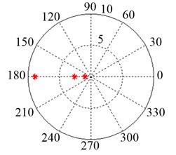
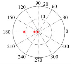
For researching dynamic stability of a rotor filled with liquid, we assume that the mass ratio 0.206 and the parameter 2.6, let 0, 1, 2, 3, 4 and 5, respectively. Then the roots of eigenequation can be obtained. Fig. 3 shows the polar diagram of the root. From Fig. 3, it can be observed that the polar angles of roots are 0, and , which explains that eigenvalues only contain imaginary part. Therefore, the solution for eigenequation can be represented as:
Substituting Eq. (33) into Eq. (8), we have:
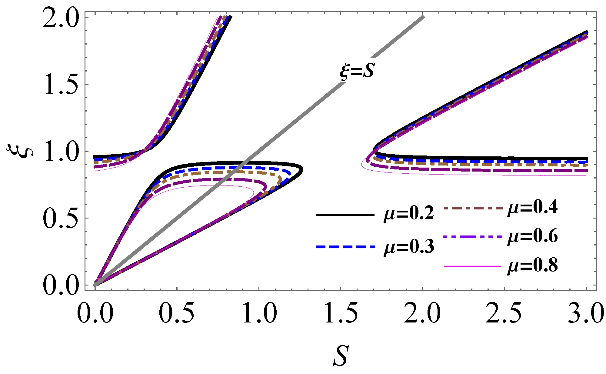
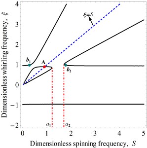
Based on Eq. (34), the plot of dimensionless whirling frequency versus dimensionless spinning frequency for 0.206 and 2.6 can be obtained, as shown in Fig. 4. We can see that there are two real roots and a pair of conjugate complex roots in the interval [, ], which illustrates that the system is unstable. Moreover, point A denotes the rotor first-order critical speed in the Fig. 4 when , the critical spinning speed can be obtained as:
Point A is on the left side of , namely, instability rotating speed is greater than first order critical speed. Therefore, one can say that rotor passes critical speed first and then system instability is occurred. Let 1, we obtain , which is corresponding to point and in Fig. 4. Thus, the estimation range of unstable region is:
From Eq. (34), it can be found that the system stability is related to the fluid-fill ratio and the mass ratio. In the following section, we will discuss the influences of system parameters on the stability of a liquid-filled rotor system.
Fig. 3Polar diagram of the roots for the system eigenequation
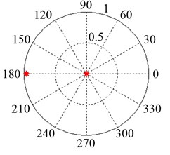
a) 0
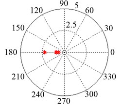
b) 1
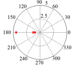
c) 2
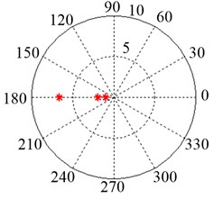
d) 3
e) 4
f) 5
Fig. 4Dimensionless whirling frequency ξ versus dimensionless spinning frequency S
4.2. The influence of parameters on the system stability
4.2.1. Fluid-fill ratio
In this paper, the function of external damping coefficient is neglected in parameters discussion. Let ; here is fluid-fill ratio, then we have:
We assume that the mass ratio is a constant, given that 0.206. Thus, the effects of the fluid-fill ratio on system stability are shown in Figs. 5-7.
Fig. 5The effects of the fluid-fill ratio x on system stability at μ=0.206
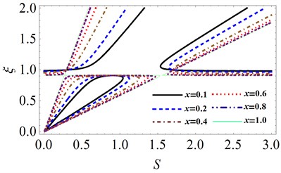
Fig. 6Variation of unstable region when fluid-fill ratio x is small
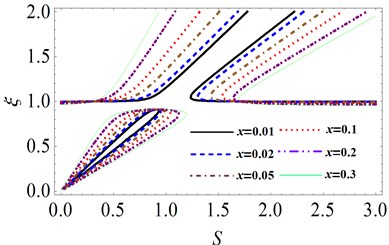
Fig. 7Variation of unstable region when fluid-fill ratio x is large
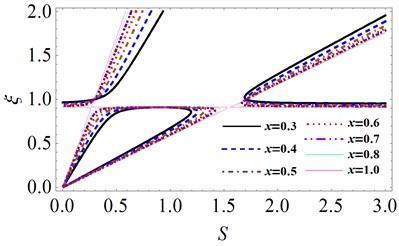
In Fig. 5, we can see that when fluid-fill ratio x is small, unstable region increases with . On the contrary, if the fluid-fill ratio is large, the unstable region will decrease gradually. Fig. 6 shows the variation of unstable region when fluid-fill ratio is small. It can be observed that when fluid-fill ratio is changed in the range of (0, 0.3], the lower and upper bounds of unstable region increase with . Due to the increasing speed of upper bound is greater than that of lower bound, the unstable region increases with fluid-fill ratio and moves towards high speed zone gradually.
Fig. 8Variation of the width of unstable region versus fluid-fill ratio x
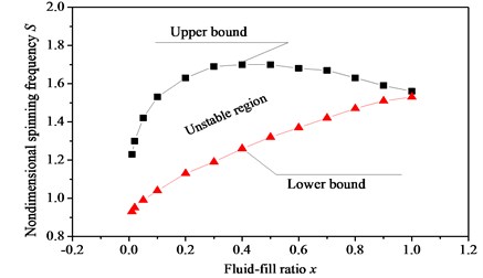
Fig. 7 shows the variation of unstable region when fluid-fill ratio is large. When fluid-fill ratio is changed in the range of (0.3, 1], the lower bound of unstable region increases as increases. However, the upper bound increases firstly, and then decreases. As a result, unstable region becomes smaller with the increasing of fluid-fill ratio . When 1, unstable region is almost disappeared, which indicates that the rotor system is stable. The width of unstable region changes with fluid-filled ratio is shown in Fig. 8. The results show that as fluid-fill ratio increases, the unstable region first expand, then narrow. If the chamber of rotor is fully filled with fluid, the instable phenomenon is disappeared.
4.2.2. Mass ratio
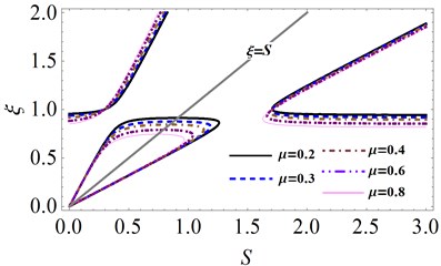
When we discuss the influence of mass ratio on the system stability, fluid-fill ratio should be taken as a constant. Let fluid-fill parameter 2.6, the effects of mass ratio on unstable region can be obtained, as shown in Fig. 9. It shows that with the growth of mass ratio , the unstable region increases gradually.
Fig. 9The effects of the mass ratio μ on system stability for γ= 2.6
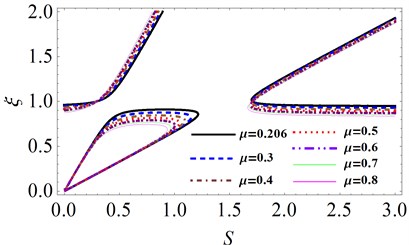
Fig. 10Variation of the width of unstable region versus mass ratio μ
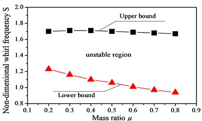
The variation of the width of unstable region versus with mass ratio is shown in Fig. 10. One can observe that when mass ratio increases, the upper bound of unstable region has little changed, but lower bound decreases obviously. Therefore, unstable region presents the tendency of increase. Moreover, the unstable region moves towards low speed zone gradually.
4.2.3. The effects of parameters changed together on unstable region
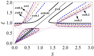
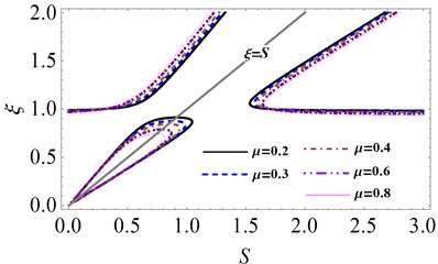
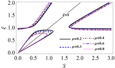
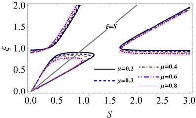
In Section 4.2.1 and Section 4.2.2, we have analyzed the effects of individual parameter on unstable region. In this section, we will take into account the combined action of fluid-fill ratio and mass ratio . The variations of unstable region are shown in Fig. 11 and Fig. 12.
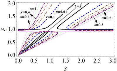
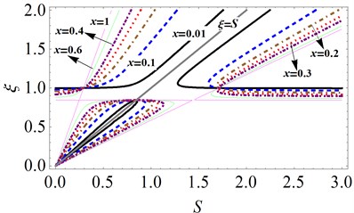
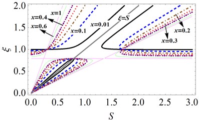
Fig. 11 shows the effects of fluid-fill ratio on unstable region under different mass ratio . It can be observed that as fluid-fill ratio increases, the unstable region first expands, then narrows. When the rotor chamber is fully filled with liquid, unstable region disappears, and the rotor system is stable. As mass ratio increases, unstable region moves to low speed zone gradually. From Fig. 11, it can be seen that the mass ratio has little influence on the width of unstable region. However, the fluid-fill ratio x gives great effects, which illustrates that fluid-fill ratio is the primary factor to affect the system stability. Moreover, as fluid-fill ratio increases, the first critical speed of the system does not vary.
Fig. 12 gives the effects of mass ratio on unstable region for different fluid-fill ratio . It shows that the unstable region increases with the growth of mass ratio . The fluid-fill ratio has a great influence on the width of unstable region, as shown in Fig. 12. As fluid-fill ratio increases, the width of unstable region increases obviously. From Fig. 12, it can be clearly seen that the first order critical speed decreases with the increase in mass ratio , which indicates that the first order critical speed is only determined by mass ratio .
Fig. 11The effects of fluid-fill ratio x on unstable region under different mass ratio μ: a) μ= 0.206, b) μ= 0.4, c) μ= 0.6, d) μ= 0.8
a)
b)
c)
d)
Fig. 12The effects of mass ratio μ on unstable region under different fluid-fill ratio x: a) x= 0.1, b) x= 0.2, c) x= 0.3, d) x= 0.4
a)
b)
c)
d)
5. Conclusions
An analytical solution has been introduced to solve the general whirling eigenequation of a rotor filled with liquid. The analytical results of the eigenequation was obtained and the validity of the proposed method was illustrated in the paper. A comparison was carried out between analytical calculation and numerical method. The results show that the maximum error of the two results is only 4.8 %, which illustrates the reasonability of the present calculation method. On the basis of whirling eigenequation, the system stability was analyzed and the effects of system parameters on unstable region were discussed. The performed investigations show that the dynamic instability occurs at a particular bound of the rotating speed for a rotor filled with liquid. The first order critical speed, which is only related to the mass ratio , is less than the instability spinning speed for the rotor system. Based on the present work, it could be found that the unstable region moves to the low speed zone as mass ratio increases. The fluid-fill ratio is the prime factor affecting the width of the unstable region. When the rotor chamber is fully filled with liquid, unstable region disappears, and the system is stable.
References
-
Kollmann F. G. Experimentelle und theoretische Untersuchungen uber die kritischen Drehzahlen flüssigkeitsgefullter Hohlkorper. Forschung Auf Dem Gebiet Des Ingenieurwesens A, Vol. 28, Issue 4, 1962, p. 115-123.
-
Jlnnouchi Y., Araki Y., Inoue J. The dynamic instability of a non-rotating pipe in a high speed rotor filled with liquid. Transactions of the Japan Society of Mechanical Engineers, Vol. 54, Issue 502, 1988, p. 1210-1216.
-
Crandall S. H. Rotating and Reciprocating Machines. Handbook of Engineering Mechanics. New York, 1962.
-
Crandall S. H., Mroszczyk J. Whirling of a flexible cylinder filled with liquid. Proceedings of International Conference on Rotor Dynamics, Tokyo, 1986.
-
Wolf J. A. Whirl Dynamics of a Rotor Partially Filled with Liquid. Transaction of the ASME Journal of Applied Mechanics, Vol. 35, Issue 4, 1968, p. 676-682.
-
Hendricks S. L., Morton J. B. Stability of a rotor partially filled with a viscous incompressible fluid. Journal of Applied Mechanics, Vol. 46, Issue 4, 1979, p. 913-918.
-
Daich I. M., Bar I. L. Oscillations of a rotating solid body with a cavity partly filled with viscous fluid. Prikl Mekh, Vol. 9, Issue 5, 1973, p. 64-69.
-
Saito S., Someya T. Self-excited vibration of a rotating hollow shaft partially filled with liquid. Journal of Mechanical Design, Vol. 102, Issue 1, 1980, p. 185-192.
-
HolmChristensen O., Trager K. A Note of instability caused by liquid motions. Journal of Applied Mechanics, Vol. 58, Issue 3, 1991, p. 804-811.
-
Hendricks S. L. Stability of a clamped-free rotor partially filled with liquid. Journal of Applied Mechanics, Vol. 53, Issue 1, 1986, p. 166-172.
-
Lichtenberg G. Vibrations of an elastically mounted spinning rotor partially filled with liquid. Journal of Applied Mechanics, Vol. 104, Issue 2, 1982, p. 389-396.
-
Ota H., Ishida Y., Sato A., Yamada T. Experiments on vibrations of a hollow rotor partially filled with liquid. Bulletin of JSME, Vol. 29, Issue 256, 1986, p. 3520-3529.
-
Sato Y. Dynamic absorber using a hollow rotor partially filled with liquid. Transactions of the Japan Society of Mechanical Engineers, Vol. 54, Issue 3, 1988, p. 446-452.
-
Kuipers M. On the stability of a flexibly mounted rotating cylinder partially filled with liquid. Applied Scientific Research, Vol. 13, Issue 1, 1964, p. 121-137.
-
Zhang W., Tang J., Tao M. Dynamic stability of a rotor filled or partially filled with liquid. Journal of Applied Mechanics, Vol. 63, Issue 1, 1996, p. 101-105.
-
ZhuChangsheng Experimental investigation into the instability of an over-hung rigid centrifuge rotor partially filled with fluid. Journal of Vibration and Acoustics, Vol. 124, Issue 4, 2002, p. 483-491.
-
Tao M., Zhang W. Dynamic stability of flexible rotating cylinder partially filled with liquid. Journal of Fudan University, Vol. 38, Issue 2, 1999, p. 141-145.
-
Ishida Y., Liu J. Elimination of unstable ranges of rotors utilizing discontinuous spring characteristics: an asymmetrical shaft system, an asymmetrical rotor system, and a rotor system with liquid. Journal of Vibration and Acoustics, Vol. 132, Issue 1, 2010, p. 325-326.
-
Derendyeav N. V. Sandalov V. M. To stability of steady-state rotation of cylinder partly filled with viscous incompressible liquid. Journal of Applied Mathematics and Mechanics, Vol. 46, Issue 4, 1982, p. 578-586.
-
Derendyaev N. V. Stability of steady rotation of a cylinder filled with a stratified viscous incompressible liquid. Fluid Mechanics and Heat Transfer, Vol. 272, Issue 5, 1983, p. 1073-1076.
-
Derendyaev N. V., Senyatkin V. A. Stability conditions for the steady-state rotation of a cylinder filled with a stratified nonuniform viscous incompressible liquid. Journal of Applied Mechanics, Vol. 25, Issue 1, 1984, p. 30-39.
-
Derendyaev N. V., Soldatov I. N. Study of stability and self-excited vibrations of a rotor with liquid on the basis of a discrete model. Proceedings of the VI Scientific Conference on Nonlinear Vibrations of Mechanical Systems, Nizhny Novgorod, 2002.
-
Derendyaev N. V. Andronov-Hopf bifurcation in the dynamics of a liquid-filled rotor system. Soviet Physics Doklady, Vol. 33, Issue 8, 1988, p. 592-594.
-
Derendyaev N. V. Nonconservative Problems of Dynamics of Rotor Systems Containing Fluid. Dissertation of Doctor of Science, Nizhny Novgorod, 1999.
-
Wu D., Rong C., Bing H. A novel two-stage hybrid swarm intelligence optimization algorithm and application. Soft Computing, Vol. 16, Issue 10, 2012, p. 1707-1722.
-
Wu D., Xinhua Y., Li Z. An improved self-adaptive differential evolution algorithm and its application. Chemo Metrics and Intelligent Laboratory Systems, Vol. 128, Issue 15, 2013, p. 66-76.
-
Wu D., Huimin Z., Jingjing L. An improved CACO algorithm based on adaptive method and multi-variant strategies. Soft Computing, Vol. 19, Issue 3, 2015, p. 701-713.
-
Wu D., Huimin Z., Li Z. A novel collaborative optimization algorithm in solving complex optimization problems. Soft Computing, Vol. 21, Issue 15, 2017, p. 4387-4398.
-
Wu D., Huimin Z., Xinhua Y. Study on an improved adaptive PSO algorithm for solving multi-objective gate assignment. Applied Soft Computing, Vol. 59, 2017, p. 288-302.
-
Zhao H.M., Li D.Y., Deng W. Research on vibration suppression method of alternating current motor based on fractional order control strategy. Proceedings of the Institution of Mechanical Engineers Part E-Journal of Process Mechanical Engineering, Vol. 231, Issue 3, 2017, p. 786-799.
-
Wu D., Rui Y., Huimin Z. A novel intelligent diagnosis method using optimal LS-SVM with improved PSO algorithm. Soft Computing, 2017, https://doi.org/10.1007/s00500-017-2940-9.
-
Wu D, Shengjie Z, Huimin Z. A novel fault diagnosis method based on integrating empirical wavelet transform and fuzzy entropy for motor bearing. IEEE Access, 2018.
-
Huimin Z., Meng S., Wu D. A new feature extraction method based on EEMD and multi-scale fuzzy entropy for motor bearing. Entropy, Vol. 19, Issue 1, 2016, p. 14.
About this article
The authors disclosed receipt of the following financial support for the research, authorship, and/or publication of this article: The work is supported by the National Science Foundation of China (Grant No. 51775093) and the National Science Foundation of China (Grant No. 51335003).
