Abstract
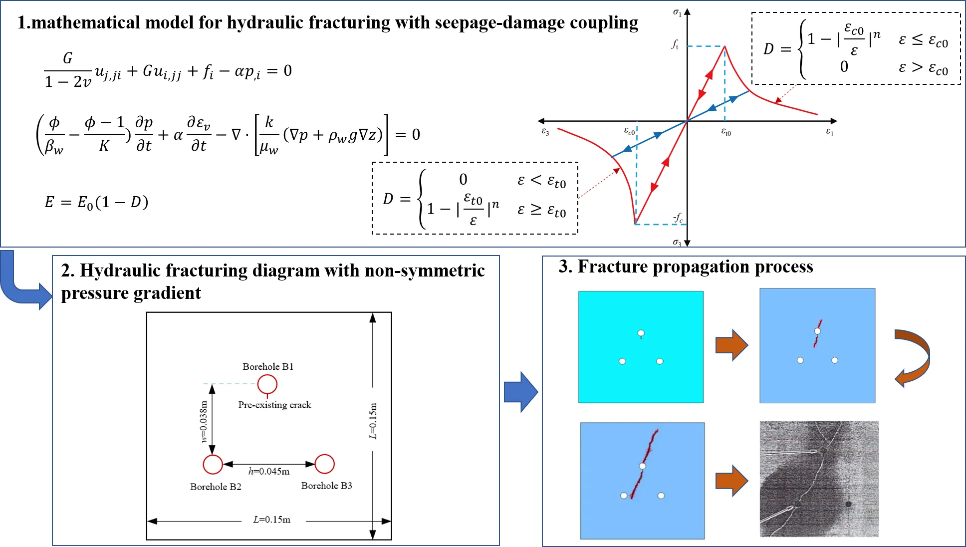
To investigate rules of fracture propagation during hydraulic fracturing in heterogeneous coal-rock mass, a new mathematical model for hydraulic fracturing with seepage-damage coupling and its numerical algorithm are proposed. The rules of coal-rock mass heterogeneity, confining pressure, beforehand hydraulic slotting, and non-symmetric pressure gradient on fracture propagation are investigated. Numerical results show the following: (1) Compared to homogeneous coal-rock mass, the fracture propagation pattern exhibits a more zig-zag characteristic and the fracture initiation pressure is reduced in heterogeneous coal-rock mass. (2) Fracture propagation during borehole fracturing is mainly controlled by confining pressure ratio, and the fracture would propagate along the path with least resistance in coal-rock mass. (3) During hydraulic fracturing with beforehand hydraulic slotting, fracture propagation pattern would become more complex with slotting length increasing; the propagation direction of fracture is primarily controlled by principal stress difference, the larger of principal stress difference, the more difficult of oriented fracturing. (4) Non-symmetric pressure gradient can reduce breakdown pressure and influence fracture propagation pattern, which provides a beneficial guide for oriented fracturing. The simulation results are consistent with the theoretical solutions and experimental observations, which is promising to guide field operation of hydraulic fracturing to improve coalbed methane extraction.
Highlights
- A new mathematical model for hydraulic fracturing with seepage-damage coupling and its numerical algorithm are proposed.
- The rules of coal-rock mass heterogeneity, confining pressure, beforehand hydraulic slotting, and non-symmetric pressure gradient on fracture propagation are investigated.
- The simulation results are promising to guide field operation of hydraulic fracturing to improve coalbed methane extraction.
1. Introduction
Coalbed methane is not only an unconventionally clean gas, but also can cause gas outburst in underground coal mine. The extraction of coalbed methane before coal mining is an important measure for prevention of gas outburst in China [1, 2]. However, as the mining depth increases, the coal-rock mass permeability would decrease significantly, causing the difficulty of coalbed methane extraction [2, 3]. To improve coal-rock mass permeability in deep underground coal mine, numerous hydraulic measures, including hydraulic slotting, high-pressure water injection, hydraulic punching and hydraulic fracturing, are proposed [2, 4, 5]. Especially the hydraulic fracturing measure, it has been widely applied in engineering practice, but some failure cases of hydraulic fracturing in coal-rock mass which cannot achieve expected goals still exist [3, 6]. The reasons are that there are many factors (e.g. in-situ stress and coal-rock mass property) affecting fracture propagation. Therefore, the premise of successful hydraulic fracturing is to ascertain rules of fracture propagation under different conditions using a reliable approach.
In recent years, scholars qualitatively studied fracture propagation during hydraulic fracturing based on field observation, laboratory experiment and numerical simulation [7-13]. For example, the microseismic monitoring method is usually used to monitor and deduce fracture azimuth and propagation direction in field observation [7, 8]; the CT scanning image is used to obtain the distribution of fracture pattern in rock specimen, or the acoustic emission location technology is used to reflect the dynamical evolution of fracture propagation in laboratory experiment [9-12]. However, in both field observation and laboratory experiment, the mechanism of fracture propagation cannot be quantitatively analyzed, and the quantitative relationship between influence factor and fracture propagation cannot be obtained. Compared with field observation and laboratory experiment, numerical simulation is verified to be an effective approach for quantitative study. Numerous numerical models have been proposed for hydraulic fracturing simulation [13-21]. In general, numerical models for hydraulic fracturing simulation could be divided into direct approach and indirect approach [15, 19]. In former approach [20, 21], rock is discretized into idealized microstructure units (e.g. springs and particles) and fractures are induced by breakages of these microstructure units. However, in indirect approach [16-19], the rock is supposed to be a continuum and fracture is represented by its non-reversible damage included in constitutive relation. Meanwhile, an accurate description of fracture propagation during hydraulic fracturing should also be accomplished with hydro-mechanical coupling [19]. Compared with the direct approach, numerical models based on indirect approach are more elaborate, which could handle multi-physical problems and behaviors of complex rock including dispersedly microcosmic pores or fissures [22, 23]. Typical capabilities of indirect models comprise individual basic elements, which are allowed to damage according to a specific strength failure criterion. Tang [16-18] developed a mathematical model with damage-flow coupling, and the influences of confining pressure and rock heterogeneity on fracture propagation had been analyzed. Zhao [14] proposed a mathematical model with seepage-damage-fracture coupling, and the fracture propagation during water inrush had been studied. Yuan [24] proposed a local degradation approach, where the hydro-mechanical coupling with element’s permeability evolution had been introduced. Lyakhovsky [25] modeled the coupling process of fluid flow and crack evolution based on a thermo-dynamic mathematical model. Li [26] had analyzed the influences of gravel content, gravel size and principal stress difference on fracture propagation in glutenite formation. Lu [19] raised a dual-scale numerical model to depict the realistic rock consisting of micro fissures, and the influencing injection rate on fracture propagation was studied. In conclusion, models based on indirect approach have been developed well, but the rock is always assumed to be impermeable; and the aforementioned studies have played a role for understanding the mechanical mechanism of fracture propagation. The rules of fracture propagation under varying conditions are not understood fully and need further study. Inspired from the existing studies, to study the rules of fracture propagation during hydraulic fracturing in heterogeneous coal-rock mass, a new numerical model with seepage-damage coupling in hydraulic fracturing of heterogeneous coal-rock mass is proposed, and coal-rock mass heterogeneity, confining pressure, beforehand hydraulic slotting, and non-symmetric pressure gradient on fracture propagation are systematically investigated. The numerical results are consistent with related theoretical solutions and experimental observations, which provide a role of guiding engineering practice of hydraulic fracturing in underground coal mine to enhance coalbed methane extraction.
2. Mathematical model for hydraulic fracturing and its numerical algorithm
Coal-rock mass is a typically heterogeneous porous material whose seepage characteristic would affect the deformation of coal-rock mass. Meanwhile, the nonlinear plastic deformation would also affect the seepage characteristic in turn. Therefore, the hydraulic fracturing process is a nonlinearly multi-physical problem [27-29]. However, the nonlinear model would lead to the increase of numerical difficulty with low precise [30, 31]. Considering the nonlinear behavior of coal-rock mass, the linear elastic damage model can be employed preferentially [31]. To study rules of fracture propagation during hydraulic fracturing in coal-rock mass, a mathematical model for hydraulic fracturing and its numerical algorithm are raised in this section. The following summarizes the governing equations, damage and permeability evolution equations, assignment of material heterogeneity, and numerical algorithm of the mathematical model.
2.1. Governing equation for coal-rock mass deformation
The governing equations could be introduced by considering pore water pressure with Biot constitutive relation [14], and further adopting of strain-displacement relation and equilibration equation. For elastic porous medium with single-phase saturated under an isothermal state, the governing equation for coal-rock mass deformation is given by [32, 33]:
where and are the shear modulus and Poisson’s ratio of coal-rock mass, respectively; is the displacement of th direction; denotes the volumetric body force of th direction; represents Biot coefficient; the footnote [] is the differentiation in regard to the coordinate ; and denotes pore pressure (negative for suction).
As can be seen from Eq. (1), it expresses the mechanical equilibrium of porous elastic medium where the effect of pore pressure on coal-rock mass deformation is accounted.
2.2. Governing equation for water seepage
The water seepage of saturated medium satisfies mass conservation equation, and further utilizing of Darcy seepage law for momentum equation [33, 34], the governing equation for water seepage is given by:
where and are the porosity and bulk modulus of coal-rock mass, respectively; , and are bulk modulus, dynamic viscosity coefficient and density of water, respectively; and are volumetric strain and permeability coefficient of coal-rock mass; is the time; denotes the gravitational acceleration, and represent the elevation.
2.3. Damage and permeability evolution equations
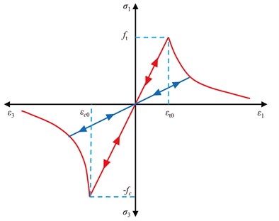
As mentioned, the elastic damage constitutive relationship would be employed to describe the damage evolution of coal-rock mass. As seen from Fig. 1, the relationship between strain and stress is assumed to be linear unless a damage threshold is satisfied. The coal-rock mass damage would initiate if its stress state reaches the Mohr-Coulomb criterion (abbreviated as C-C in short) or tensile stress criterion (abbreviated as T-C in short). In numerical algorithm, the T-C is always prior to C-C, namely, T-C is adopted first to ascertain whether tensile damage initiates in coal-rock mass or not, if the it doesn’t damage according to T-C, then the damage of coal-rock mass would be checked based on C-C. The mathematical functions of T-C and C-C can be given by [35]:
where , and represent the internal frictional angle, compressive strength, and tensile strength of coal-rock mass, respectively; and denote damage initiation functions for T-C and C-C, respectively. It should be noted that Eqs. (3), (4) operate on effective stress space.
Fig. 1Elastic damage constitutive relations for coal-rock mass under uniaxial conditions
Based on elastic damage mechanics, as the evolution of damage, the coal-rock mass mechanical parameter, such as Young’s modulus , would linearly degrade in accordance with following function [31]:
where denotes the initial Young’s modulus of coal-rock mass before damage initiates; while denotes the damage variable, which ranges from 0 to 1.
The constitutive relations of coal-rock mass under uniaxial tension and compressive conditions can be deduced from Fig. 1. If the coal-rock mass is under tension damage condition, its damage variable can be calculated by [33]:
where represents the threshold strain of coal-rock mass when tensile damage initiates; is called the constitutive coefficient which equals to 2.0.
In analogy with the damage evolution under uniaxial tension condition, when the coal-rock mass satisfies the C-C under uniaxial compression condition, its damage variable can be calculated by [33]:
where represents the threshold strain of coal-rock mass when shear damage initiates. With the degradation evolution of mechanical strength or stiffness of coal-rock mass, it would experience dilatancy, which would seriously change the hydraulic properties. The coal-rock mass porosity, , which is strongly related to its stress conditions, can be calculated as [34]:
where represents the original porosity without stress; represents the residual porosity in infinite stress state; represents the effective stress calculated by /3, where (, 1, …, 3) represents the corresponding stress tensor; and is called stress sensitivity coefficient with value being 5.0×10⁻⁸ Pa-1.
Furthermore, the permeability of coal-rock mass would also evolve during damage accumulation. Based on previous studies [34], the permeability is strongly dependent on the porosity of coal-rock mass, and then the permeability could be deduced according to the following exponential function as:
where is called index coefficient with value being 3.0; is called damage-permeability coefficient with value being 5.0; denotes the permeability without stress; and could be calculated by Eqs. (6), (7).
2.4. Assignment of material heterogeneity
As the realistic coal-rock mass contains dispersed cementing materials and various mineral particles, which cause its mechanical properties to exhibit characteristics of heterogeneity. To characterize such heterogeneity of the coal-rock mass, assuming that it is composed of many mesoscopic elements, whose physical and mechanical parameters conform to a given Weibull distribution whose probability density function is [19]:
where represents the element’s mechanical parameter (e.g. elastic modulus), represents the average value for all elements, and is called homogeneity index of element parameter . According to characteristics of Weibull distribution, with the increase of , the mechanical parameters of more elements will be closer to value of , and thus generating a more homogeneous coal-rock mass specimen. Previous results indicate that when is greater than 1000, the rock can be assumed as a homogeneous material [1].
2.5. Numerical algorithm
The aforementioned Eqs. (1)-(10) constitutes the mathematical model for hydraulic fracturing with seepage-damage coupling. The effect of water seepage on coal-rock mass deformation behavior is considered in Eq. (1), while the effect of coal-rock mass deformation on water seepage behavior is considered in Eq. (2). Moreover, the damage-induced evolution of porosity and permeability are considered in Eqs. (8), (9). Eq. (1) and Eq. (2) are both nonlinear, which are impossible to solve theoretically. In this respect, a numerical algorithm for the solution of mathematical model is proposed instead. The procedure of proposed numerical algorithm is as follows:
Step 1: After the geometry model is built, it is then discretized into numerous finite elements, whose mechanical parameters satisfy the Weibull distribution (see Eq. (10)) using a Monte Carlo simulation method coded by Matlab program. Moreover, to ensure the numerical model is in a quasi-static response, the prescribed boundary load on model is divided into several loading increments.
Step 2: For every loading increment, the Comsol program [36] is used to execute a fully coupled calculation according to governing Eqs. (1), (2), and numerical results of all finite elements (such as effective stress and displacement) are obtained for the following step.
Step 3: Substituting obtained effective stress of all finite elements into Eqs. (3), (4), and then the damage states of all elements can be determined. When an element is in damage state, damage variable at its corresponding node is calculated using Eq. (6) or Eq. (7), and then the elastic modulus and permeability at its node can be calculated using Eq. (5) and Eq. (9), thus forming a new numerical model with updated mechanical parameters. Furthermore, the second and third steps are cycled to judge the damage state of each element. The next loading increment is applied when a specific convergence criterion is satisfied: / < 1×10⁻⁵, where represents the solution step during numerical calculation, and denotes the damage variable matrix.
In a word, the above procedure of the numerical algorithm is coded into a Matlab program combined with Comsol program to solve mathematical model for hydraulic fracturing with seepage-damage coupling.
3. Numerical results and analysis
3.1. Influence of coal-rock mass heterogeneity on fracture propagation
To investigate how coal-rock mass heterogeneity influences the fracture propagation during hydraulic fracturing, two numerical models with homogeneity indexes of 1000 and 20 are established. Fig. 2 presents the geometry and corresponding boundary conditions for two numerical models. Related parameters adopted are presented in Table 1. The vertical stress and horizontal stress applied on boundaries are 15.45 MPa and 10.30 MPa, respectively. The initial water pressure in calculation domain is set to 0.0 MPa, while the pressurization rate on the wall of fracturing borehole is 0.5 MPa/step.
To realistically simulate the hydraulic fracturing process, the calculation scheme is divided into two steps. Firstly, the initial stress state before hydraulic fracturing is calculated by performing a mechanical-only solution. Secondly, a fully coupled seepage-damage solution is executed with the equilibrium state in the first step being the initial condition.
Table 1Related parameters for numerical solution
Parameter | Value | Parameter | Value |
Compressive strength | 40 MPa | Original porosity | 0.05 |
Tensile strength | 3 MPa | Residual porosity | 0.01 |
Poisson’s ratio | 0.33 | Water bulk modulus | 2.5×10⁹ Pa |
Elastic modulus | 3.35 GPa | Water dynamic viscosity | 3.55×10⁻⁴ Pa.s |
Biot coefficient | 0.8 | Homogeneity index | 1000, 20 |
Internal friction angle | 30° | Initial permeability | 3×10-18 m2 |
Fig. 2Geometry and corresponding boundary conditions for two numerical models
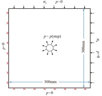
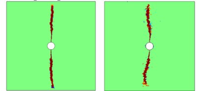
Fig. 3 illustrates two distribution diagrams for the first principal stress field and fracture propagation pattern with homogeneity indexes being 1000 and 20.
Fig. 3Distribution diagrams of stress field and fracture propagation pattern
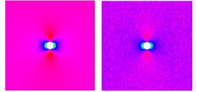
a) First principal stress field, 1000
b) Fracture propagation pattern, 20
As seen from Fig. 3, the stress existed in heterogeneous model with being 20 exhibit roughness and discontinuity compared with homogeneous model with being 1000. In other words, coal-rock mass heterogeneity has a significant role in the modification of stress field; meanwhile, the path of fracture propagation in heterogeneous model exhibits a more zig-zag characteristics than that of the homogeneous model. Compared to numerical model with homogeneity index of 1000, there are more randomly distributed defects and grains in model with homogeneity index of 20. Therefore, the mechanical behavior of coal-rock mass at different locations of the numerical model with homogeneity index of 20 are more different. After the external load is applied, local stress concentrations would occur as a result of the different stress or deformation transfer abilities of coal-rock mass constitutes, thus causing the change of fracture propagation pattern and extension of local microcracks.
Moreover, numerical simulation results indicates that if the hydraulic pressure in fracturing borehole is increased to a certain pressure, two nearly symmetrical fractures (denoted by damaged elements) start to initiate. Such critical pressure is called fracture initiation pressure. The fracture initiation pressures for the homogeneous model ( 1000) and heterogeneous model ( 20) are 13.5 MPa and 12 MPa, respectively. Namely, with the decrease of homogeneity index, the fracture initiation pressure would also reduce, which conforms to related theoretical analysis and engineering practice [17, 37, 38]. Thus, the characteristics of coal-rock mass heterogeneity should be investigated before the operation of engineering practice of hydraulic fracturing.
3.2. Influence of confining pressure on fracture propagation
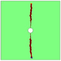
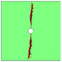
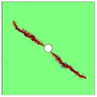
To study how confining pressure influences fracture propagation (including fracture propagation pattern, fracture initiation or breakdown pressure [19]), three heterogeneous numerical models with homogeneity index of 20 are used. The horizontal boundary stress is kept at 10.30 MPa, while the ratios of vertical stress to horizontal stress (/) are set to 1.5, 1.25 and 1.0, respectively. The model geometry and its corresponding boundary conditions are shown in Fig. 2. Related parameters for hydraulic fracturing simulation are presented in Table 1. The fracture propagation patterns under varying confining pressures are illustrated in Fig. 4.
Fig. 4Fracture propagation patterns under varying confining pressures
a)/ 1.5
b)/ 1.25
c)/ 1.0
As seen from Fig. 4, at a larger confining pressure ratio of / 1.5, two nearly straight fractures propagate approximately orthogonal to direction of minimum principal stress (Fig. 4(a)). With the decrease of confining pressure ratio, the dominant fractures gradually extend, and they start to deviate from orientations of initial fractures; besides, some fractures would branch as hydraulic fracturing continues, and their propagation paths become devious and coarse. Especially when confining pressure ratio is 1.0 (namely, a hydrostatic pressure condition as shown in Fig. 5(c)), the randomly distributed defects and grains in coal-rock mass would significantly affect the path of fracture propagation; in other words, the micro fractures would initiate at the weakest region, causing the hydraulic fractures randomly propagate. In short, based on the results of numerical calculation, it could be concluded that fracture propagation is mainly controlled by confining pressure ratio, the hydraulic-induced fracture would always select the path with least resistance in coal-rock mass; and an irregular fracture path would occur due to the random locations of weak parts; perfectly planar fractures, which are parallel to any principal stress direction, are impossible in realistic engineering practice.
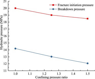
Fig. 5 presents simulation results of fracture breakdown pressure and initiation pressure under varying confining pressures. The breakdown pressures, , are 20 MPa and 18.5 MPa for confining pressure ratios of 1.0 and 1.5, respectively, which are consistent with the trend of theoretical analysis calculated by -+[17, 39]. With confining pressure ratio increasing, the fracture initiation or fracture breakdown pressure would decrease. The main reason is that the circumferential stress (positive for tension) at the top or bottom borehole boundary would increase with confining pressure ratio increasing, and then initial fractures initiate at these regions, which provide a path for water flow and further cause the extension or propagation of hydraulic fractures, and thus reducing the breakdown pressure for coal-rock mass.
Fig. 5Fracture breakdown and initiation pressure under varying confining pressures
3.3. Influence of beforehand hydraulic slotting on fracture propagation
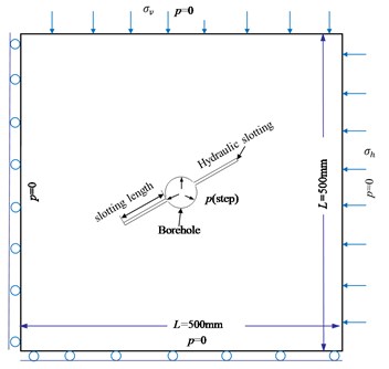
Hydraulic fracturing or hydraulic slotting each has its own advantage of enhancing coalbed methane extraction. On basis of the two measures, scholars proposed the oriented fracturing technology with beforehand hydraulic slotting recently [40, 41]. The key of the oriented fracturing technology is to ascertain the influence rules of beforehand hydraulic slotting on fracture propagation. The influence of two major factors (including slotting length and principal stress difference) on fracture propagation are studied. The model geometry and its corresponding boundary conditions are presented in Fig. 6. Related parameters for hydraulic fracturing simulation are presented in Table 1. The horizontal stress on boundary is 10.30 MPa. The calculation scheme is also divided into two steps as mentioned in section 3.1. The initial water pressure in computation domain is set to 0.0 MPa, while the pressurization rate in fracturing borehole is 0.5 MPa/step.
Fig. 6Model geometry and boundary conditions
3.3.1. Influence of slotting length on fracture propagation
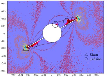
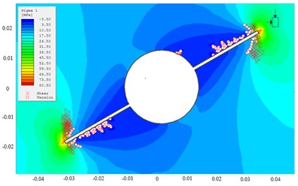
In present numerical models, the angle between slotting and horizontal boundary stress is kept at 30°, the vertical stress on boundary is 15.45 MPa, the slotting lengths are set to 25 mm, 50 mm and 125 mm for cases 1-3, respectively. The damage regions at the initial equilibrium step of case 1 are illustrated in Fig. 7(a), in which the tensile and shear damage are denoted by “○” and “△”, respectively. As seen from Fig. 7(a), regions with shear damage mainly occur at the slotting tips, while the regions with tensile damage occur at slotting tips, bottom of left slotting and upper of right slotting. With the evolution of damage, the mechanical strength of damage regions would reduce, which can be assumed as weak parts in coal-rock mass, thus affecting the fracture propagation pattern and fracture initiation pressure. For comparison and validation, the yield regions simulated by Phase2 software [42] are shown in Fig. 7(b). As illustrated in Fig. 7, the damage regions are consistent with the yield regions. However, as the numerical model adopted in present study has considered the coal-rock mass heterogeneity, the stress contours present discontinuity and roughness compared with the homogeneous model simulated by Phase2 software.
Fig. 7Damage and yield regions at the initial equilibrium step
a) Damage regions
b) Yield regions using Phase2 software
Fig. 8 presents the fracture propagation processes for different cases. As shown in Figs. 8(a), (b), the fracture propagation patterns of cases 1 and 2 are similar to the branch cracks propagation in compressive-shear stress state in references [43-45]. However, the differences are that the locations of fracture initiation are at a distance from slotting tips, and the directions of fracture initiation are approximately perpendicular to slotting directions.
As hydraulic fractures propagate, the propagation directions of fracture wings deviate to directions of vertical principal stresses. The fracture propagation pattern presents a “” type, which is similar to the experimental results in references [43-45]. When the slotting length is 125 mm (Fig. 8(c)), due to the coal-rock mass heterogeneity and local stress concentrations at slotting location, more tensile damage regions would exist at the slotting tips and upper of right slotting, thus providing paths for water flowing, and then the fracture propagation pattern become more complex, where two primary branch cracks are generated at the slotting tips and upper of right slotting, causing the increase of the fracture breakdown pressure.
In brief, when the angle between hydraulic slotting and horizontal stress is 30°, and ratio of vertical stress to horizontal stress / 1.5, hydraulic-induced fractures don’t directly propagate along the orientation of pre-existing hydraulic slotting but initiate at a distance from slotting tips, and they finally deviate to the orientation of maximum principal stress; the larger length of hydraulic slotting, the stronger tendency of fracture deviation, and the more difficult for oriented fracturing.
Fig. 8Fracture propagation processes for different cases

a) Case 1

b) Case 2

c) Case 3
3.3.2. Influence of principal stress difference on fracture propagation
In present numerical models, the angle between slotting and horizontal boundary stress is set to be 30°, and the slotting length is kept at 50 mm. To investigate influence of principal stress difference on fracture propagation, three cases are chosen, whose ratios of vertical stress to horizontal stress are 3, 1.5 and 1.25, respectively. The fracture propagation patterns with varying principal stress differences are illustrated in Fig. 9. The angle between the directions of hydraulic slotting and fracture propagation are called deviation angle.
As shown in Fig. 9, with the decrease of ratio of vertical stress to horizontal stress (/), the deviation angle between direction of hydraulic fracture and hydraulic slotting gradually reduces. When / is less than 1.25, the deviation angle is close to 0°. In other words, when the principal stress difference is lower than 2.58 MPa, the hydraulic fracture would propagate along the pre-existing hydraulic slotting. Theoretically, when the difference of principal stress is less than a critical value, the tensile damage regions mainly occur at the slotting tips other than other locations, which are beneficial for the fracture propagation along the pre-existing hydraulic slotting.
On basis of numerical results in sections 3.3.1 and 3.3.2, it can be inferred that the direction of fracture propagation with beforehand hydraulic slotting is mainly controlled by principal stress difference, the larger of principal stress difference, the more difficult of the oriented fracturing with beforehand hydraulic slotting. Thus, in practical engineering, a preliminary investigation of initial ground stress and reasonable design of hydraulic slotting parameters are required to achieve the goal of oriented fracturing with beforehand hydraulic slotting.
Fig. 9Fracture propagation patterns for varying principal stress differences
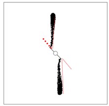
a)/ 3
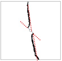
b)/ 1.5
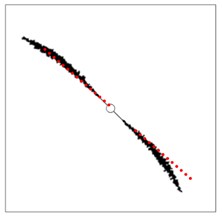
c)/ 1.25
3.4. Influence of non-symmetric pressure gradient on fracture propagation
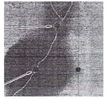
The experimental studies of Bruno [46, 47] indicated that the pore pressure had an influence on fracture propagation during hydraulic fracturing. The experimental method is as follows (Fig. 10). Firstly, three boreholes are drilled in a rock sample, and a constant hydraulic pressure is kept in borehole B2. Then, oil is gradually injected into borehole B1 to increase pressure to induce fractures, and the borehole B3 is not loaded by hydraulic pressure. The experimental result had illustrated that pore pressure had an influence on fracture propagation. However, the fracture initiation and propagation processes are not observed. Thus, the influence mechanism of non-symmetric pressure gradient on hydraulic fracturing is not understood fully and needs further study.
Fig. 10Hydraulic fracturing diagram of rock sample with three boreholes
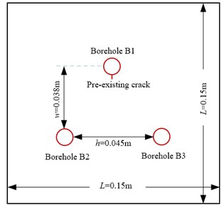
Motivated by the experiment designed by Bruno, a numerical calculation model is built according to the experiment conducted as shown in Fig. 10. The three boreholes, each with a diameter of 4mm, are named B1, B2, B3. A small pre-existing crack is designed near the bottom of borehole B1. No initial stress is loaded on the model boundary during numerical simulation. The initial hydraulic pressure applied on borehole B1 is 1.0 MPa, and is increased at 0.5 MPa/step. The hydraulic pressure in borehole B2 is kept at 1.5 MPa or 0.8 MPa, and borehole B3 is free from hydraulic pressure. The related parameters used for hydraulic fracturing simulation are shown in Table 2 [46].
Table 2Parameters used for numerical simulation
Parameter | Value | Parameter | Value |
Compressive strength | 80 MPa | Permeability coefficient | 1 m/d |
Tensile strength | 8 MPa | Original porosity | 0.05 |
Elastic modulus | 10 GPa | Residual porosity | 0.01 |
Poisson’s ratio | 0.25 | Dynamic viscosity | 5×10⁻⁴ Pa.s |
Internal friction angle | 30° | Biot coefficient | 0.8 |
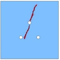
Figs. 11, 12 present the processes of fracture propagation driven by hydraulic pressure. As shown in Figs. 11(a)-12(a), the initial hydraulic fracture initiates from the pre-existing crack. When the length of hydraulic fracture reaches to a critical extent, the hydraulic fracture doesn’t extend downwards along pre-existing crack but deviates to borehole B2; meanwhile, at the top boundary of borehole B1, another hydraulic fracture which is symmetrical to the pre-existing crack is observed (Figs. 11(b)-12(b)). The fracture propagation patterns indicate that the fracture propagation path is not regular and fracture surface is coarse, which has a good similarity with the results observed in previous section 3.2.
Fig. 11Fracture propagation process (pressure in B2 is 0.8 MPa)

a) Fracture initiation stage
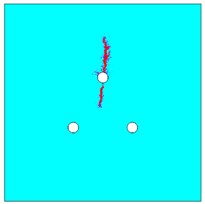
b) Fracture stable propagation stage
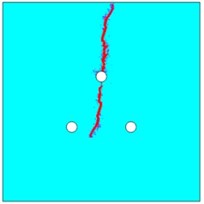
c) Final stage
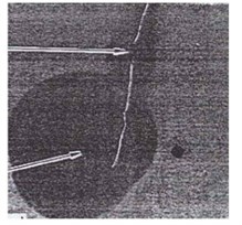
d) Experimental result [46]
Moreover, as the distance between hydraulic-induced fracture and borehole B2 decreases, the influence of pore water pressure on fracture propagation becomes more obvious. As hydraulic pressure in borehole B2 increases, the hydraulic-induced fracture has a more obvious tendency of deviation to borehole B2 (Figs. 11(c)-12(c)).
Numerical results show that the hydraulic-induced fractures are mainly composed of elements under tensile damage state, thus the orientation of fracture propagation is nearly orthogonal with maximum tensile stress direction. In theory, when the hydraulic pressure in borehole B2 is unchanged, a maximum tensile stress would be generated in the perpendicular orientation of line connecting boreholes B1 and B2, resulting in that the hydraulic-induced fracture would propagate towards borehole B2. Furthermore, the breakdown pressures are 4.62MPa and 3.84MPa when the hydraulic pressures in borehole B2 are 0.8MPa and 1.5MPa, respectively. The greater the constant hydraulic pressure in borehole B2, the less the breakdown pressure in borehole B1. The aforementioned numerical results are consistent with the experimental results as illustrated in Figs. 11(d)-12(d).
In conclusion, a non-symmetric pressure distribution can be induced on a global scope due to the local pressure gradient between borehole B1 and B2. At the fracture initiation stage (Figs. 11(a)-12(a)), as the tip of pre-existing crack is relatively far apart from borehole B2, and then the non-symmetric pressure distribution has little effect on fracture propagation yet. However, at the fracture stable propagation stage (Figs. 11(b)-12(b)), when the hydraulic-induced fracture approaches to zones with non-symmetric pore pressure distribution, effect of pore pressure on propagation of fracture would gradually increase. The greater the constant hydraulic pressure in borehole B2, the more non-symmetric the pore pressure distribution. Thus, the above results have a beneficial guiding for oriented fracturing. In engineering practice, a reasonable arrangement of multiple boreholes can be arranged, and then hydraulic pressures are applied in several boreholes to generate a suitable non-symmetric pressure gradient, which could make the fracture propagate according to a specific direction.
Fig. 12Fracture propagation process (pressure in B2 is 1.5 MPa)

a) Fracture initiation stage
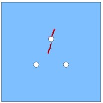
b) Fracture stable propagation stage
c) Final stage
d) Experimental result [46]
4. Conclusions
In present work, a new mathematical model for hydraulic fracturing with seepage-damage coupling and its numerical algorithm are proposed, and then influences of coal-rock mass heterogeneity, confining pressure, beforehand hydraulic slotting and non-symmetric pressure gradient on fracture propagation are systematically investigated. The conclusions obtained are as follows:
1) The proposed mathematical model for hydraulic fracturing with seepage-damage coupling and its numerical algorithm can well describe the fully coupled process during hydraulic fracturing, which provide a new useful tool for numerical investigation on hydraulic fracturing.
2) The heterogeneity of coal-rock mass has a strong influence on modification of coal-rock mass stress field. The path of fracture propagation in heterogeneous model would exhibit a more zig-zag characteristics than that of homogeneous model, and fracture initiation pressure of heterogeneous model is reduced compared to that of homogeneous model.
3) The fracture propagation during borehole fracturing is mainly controlled by confining pressure ratio, hydraulic fracture would always propagate along the path with least resistance in coal-rock mass.
4) For oriented fracturing, the fracture propagation pattern would become more complex as slotting length increases during hydraulic fracturing with beforehand hydraulic slotting; and the larger of principal stress difference, the more difficult of oriented fracturing; a suitable non-symmetric pressure gradient can be produced in coal-rock mass to make hydraulic fracture propagate along a certain direction. The above results have a beneficial guiding significance for hydraulic fracturing in underground coal mine to enhance coalbed methane extraction.
References
-
Yuan Z., Shao Y., Zhu Z. Similar material simulation study on protection effect of steeply inclined upper protective layer mining with varying interlayer distances. Advances in Civil Engineering, Vol. 2019, 2019, p. 9849635.
-
Xie H., Zhou H., Xue D., Wang H., Zhang R., Gao F. Research and consideration on deep coal mining and critical mining depth. Journal of China Coal Society, Vol. 37, Issue 4, 2012, p. 535-542.
-
Yuan Z., Shao Y. Numerical modeling on hydraulic fracturing in coal-rock mass for enhancing gas drainage. Advances in Civil Engineering, Vol. 2018, 2018, p. 1485672.
-
Wang Y., He X., Wang E., Lu Z. Research progress and development tendency of the hydraulic technology for increasing the permeability of coal seams. Journal of China Coal Society, Vol. 39, 2013, p. 1945-1955.
-
Zhu W., Wei C., Li S., Wei J., Zhang M. Numerical modeling on destress blasting in coal seam for enhancing gas drainage. International Journal of Rock Mechanics and Mining Sciences, Vol. 59, 2013, p. 179-190.
-
Fu X. Study of underground point hydraulic fracturing increased permeability technology. Journal of China Coal Society, Vol. 36, Issue 8, 2011, p. 1317-1321.
-
Zhao X., Dai T., Ju Y., Hu H., Yang Y., Gong W. Numerical study on fracture initiation and propagation of reservoirs subjected to hydraulic perforating. Journal of Mining and Safety Engineering, Vol. 33, Issue 3, 2016, p. 544-550.
-
Sun J., Wang L., Hou H. Application of micro-seismic monitoring technology in mining engineering. International Journal of Mining Science and Technology, Vol. 22, Issue 1, 2012, p. 79-83.
-
Nie B., He X., Li X., Chen W., Hu S. Meso-structures evolution rules of coal fracture with the computerized tomography scanning method. Engineering Failure Analysis, Vol. 41, 2014, p. 81-88.
-
Ju Y., Yang Y., Chen J., Liu P., Dai T., Guo Y., Zheng L. 3D reconstruction of low-permeability heterogenous glutenites and numerical simulation of hydraulic fracturing behavior. China Science Bulletin, Vol. 61, Issue 1, 2016, p. 82-93.
-
Zhao Y., Zhang L., Wang W., Tang J., Lin H., Wan W. Transient pulse test and morphological analysis of single rock fractures. International Journal of Rock Mechanics and Mining Sciences, Vol. 91, 2017, p. 139-154.
-
Cao P., Liu T., Pu C., Lin H. Crack propagation and coalescence of brittle rock-like specimens with pre-existing cracks in compression. Engineering Geology, Vol. 187, 2015, p. 113-121.
-
Yan F., Zhu C., Guo C., Zhang Q. Numerical simulation parameters and test of cutting and fracturing collaboration permeability-increasing technology. Journal of China Coal Society, Vol. 40, Issue 4, 2015, p. 823-829.
-
Zhao Y., Luo S., Wang Y, Wang W., Zhang L., Wan W. Numerical analysis of karst water inrush and a criterion for establishing the width of water-resistant rock pillars. Mine Water and the Environment, Vol. 36, Issue 4, 2017, p. 508-519.
-
Zhang B., Li X., Wang Yu, Wu Y., Li G., Li X., Wang Y. Current status and prospect of computer simulation techniques of hydraulic fracturing in oil and gas field. Journal of Engineering Geology, Vol. 2, 2015, p. 301-310.
-
Zhu W., Tang C. Micromechanical model for simulating the fracture process of rock. Rock Mechanics and Rock Engineering, Vol. 37, Issue 1, 2004, p. 25-56.
-
Yang T., Zhu W., Yu Q., Liu H. The role of pore pressure during hydraulic fracturing and implications for groundwater outbursts in mining and tunneling. Hydrogeology Journal, Vol. 19, Issue 5, 2011, p. 995-1008.
-
Li L., Tang C., Li G., Wang S., Liang Z., Zhang Y. Numerical simulation of 3D hydraulic fracturing based on an improved flow-stress-damage model and a parallel FEM technique. Rock Mechanics and Rock Engineering, Vol. 45, Issue 5, 2012, p. 801-818.
-
Lu Y., Elsworth D., Wang L. Microcrack-based coupled damage and flow modeling of fracturing evolution in permeable brittle rocks. Computers and Geotechnics, Vol. 49, Issue 4, 2013, p. 226-244.
-
Wang T., Zhou W., Chen J., Xiao X., Li Y., Zhao X. Simulation of hydraulic fracturing using particle flow method and application in a coal mine. International Journal of Coal Geology, Vol. 121, 2014, p. 1-13.
-
Schlangen E., Garboczi E. Fracture simulations of concrete using lattice models: computational aspects. Engineering Fracture Mechanics, Vol. 57, Issues 2-3, 1997, p. 319-332.
-
Zhao Y., Zhang L., Wang W., Wan W., Li S., Ma W., Wang Y. Creep behavior of intact and cracked limestone under multi-level loading and unloading cycles. Rock Mechanics and Rock Engineering, Vol. 50, Issue 6, 2017, p. 1409-1424.
-
Zhao Y., Zhang L., Wang W., Pu C., Wan W., Tang J. Cracking and stress-strain behavior of rock-like material containing two flaws under uniaxial compression. Rock Mechanics and Rock Engineering, Vol. 49, Issue 7, 2016, p. 2665-2687.
-
Yuan S., Harrison J. Development of a hydro-mechanical local degradation approach and its application to modeling fluid flow during progressive fracturing of heterogenous rocks. International Journal of Rock Mechanics and Mining Sciences, Vol. 42, Issues 7-8, 2005, p. 961-984.
-
Lyakhovsky V., Hamiel Y. Damage evolution and fluid flow in poroelastic rock. Izvestiya, Physics of the Solid Earth, Vol. 43, Issue 1, 2007, p. 13-23.
-
Li L., Li G., Meng Q. Numerical simulation of propagation of hydraulic fractures in glutenite formation. Rock and Soil Mechanics, Vol. 34, Issue 5, 2013, p. 1501-1507.
-
Jing L. A review of techniques, advances and outstanding issues in numerical modelling for rock mechanics and rock engineering. International Journal of Rock Mechanics and Mining Sciences, Vol. 40, Issue 3, 2003, p. 283-353.
-
Zhao Y., Wang Y., Wang W., Wan W., Tang J. Modeling of non-linear rheological behavior of hard rock using triaxial rheological experiment. International Journal of Rock Mechanics and Mining Sciences, Vol. 93, 2017, p. 66-75.
-
Sheng J. Fully coupled thermo-hydro-mechanical model of saturated porous media and numerical modelling. Chinese Journal of Rock Mechanics and Engineering, Vol. 25, Issue 1, 2006, p. 3028-3033.
-
Zhao Y., Zhang L., Wang W., Wan W., Ma W. Separation of elasto-visco-plastic strains of rock and a nonlinear creep model. International Journal of Geomechanics, Vol. 18, Issue 1, 2018, p. 04017129.
-
Krajcinovic D. Damage mechanics: accomplishments, trends and needs. International Journal of Solids and Structures, Vol. 37, Issues 1-2, 2000, p. 267-277.
-
Biot M. General theory of three-dimensional consolidation. Journal of Applied Physics, Vol. 12, Issue 2, 1941, p. 155-164.
-
Zhu W., Wei C., Tian J., Yang T., Tang C. Coupled thermal-hydraulic-mechanical model during rock damage and its preliminary application. Rock and Soil Mechanics, Vol. 30, Issue 12, 2009, p. 3851-3857.
-
Rutqvist J., Tsang C. A case of cap rock hydromechanical changes associated with CO2-injection into a brine information. Environmental Geology, Vol. 42, 2002, p. 296-305.
-
Hao Y., Wu Y, Mao X., Li Pan., Zhang L., Tao J. An elastoplastic softening damage model for hydraulic fracturing in soft coal seams. Advances in Civil Engineering, Vol. 2018, 2018, p. 2548217.
-
COMSOL Multiphysics Version 3.5. User’s Guide and Reference Guide. Comsol, 2008.
-
Hubbert M., Willis D. Mechanics of hydraulic fracturing. Developments in Petroleum Science, Vol. 210, 1972, p. 369-390.
-
Haimson B., Fairhurst C. Initiation and extension of hydraulic fractures in rocks, Society of Petroleum Engineers Journal, Vol. 7, 1967, p. 310-318.
-
Zhao Y., Wang, Y. Wang W., Tang L., Liu Q., Chen G. Modeling of rheological fracture behavior of rock cracks subjected to hydraulic pressure and far field stresses. Theoretical and Applied Fracture Mechanics, Vol. 101, 2019, p. 59-66.
-
Fu X., Liu H., Yang T., Yang H. Simulating directional hydraulic fracturing through coal seam drilling hole. Journal of Northeastern University (Natural Science), Vol. 32, Issue 10, 2011, p. 1480-1483.
-
Cheng Z., Min L., Chen S., Zhang J., Yang W., Li Q. Guiding-controlling technology of coal seam hydraulic fracturing fractures extension. International Journal of Mining Science and Technology, Vol. 22, Issue 6, 2012, p. 831-836.
-
Luo Z., Liu X., Wu Y., Liu W., Zhang B. Study on cavity stability numerical simulation based on coupling of Surpac and Phase2. Journal of Liaoning Technical University, Vol. 27, Issue 4, 2008, p. 485-489.
-
Feng Y., Kang H. The initiation of I-II mixed mode crack subjected to hydraulic pressure in brittle rock under compression. Journal of China Coal Society, Vol. 38, Issue 2, 2013, p. 226-232.
-
Li B., Zhu Z. Numerical and experimental research on the fracture and propagation of the branch crack under compression. Journal of China Coal Society, Vol. 38, Issue 7, 2013, p. 1207-1214.
-
Zhao Y. Mini-crack development from a cemented fracture in marble specimen under uniaxial compression. Chinese Journal of Rock Mechanics and Engineering, Vol. 23, Issue 15, 2004, p. 2504-2509.
-
Bruno M., Nakagawa F. Pore pressure influence on tensile fracture propagation in sedimentary rock. International Journal of Rock Mechanics and Mining Sciences, Vol. 28, Issue 4, 1991, p. 261-273.
-
Song C., Lu Y., Tang H., Jia Y. A method for hydro-fracture propagation control based on non-uniform pore pressure field. Journal of Natural Gas Science and Engineering, Vol. 33, 2016, p. 287-295.
About this article
This work is supported by the National Natural Science Foundation of China (Grant No. 51604111); the Scientific Research Fund of Hunan Provincial Education Department (Grant No. 16C0654); the Hunan Provincial Natural Science Foundation of China (Grant No. 2017JJ2082 and 2017JJ3072); and the Doctoral Scientific Research Foundation of Hunan University of Science and Technology (Grant No. E51502).
