Abstract
To investigate the formation of zonal disintegration phenomenon in deep rock mass under high axial geostress, 3D geomechanical model tests for two rock strengths are carried out via capacity of deep rock breakage mechanics and supporting technique model test. Considering the maximum principal stress along the tunnel axis, 3D geomechanical model tests are carried out in a loading procedure of first loading to initial geostress, then excavating the tunnel with blasting construction, and finally overloading the stress along the tunnel. Due to unloading effect, radial strain is tensile and tangential strain is compressive around excavated tunnel after excavation complete, which indicates a radial tension and circumferential compression stress state. With continuous overloading of axial stress, values of both radial tensile strain and tangential compressive strain increase, then ring fracture appears due to large radial tensile strain. After axial overloading, an interval distribution of peaks and troughs is shown in radial tensile strain distribution around excavated tunnel, which indicates a formation of zonal disintegration. By cutting the rectangular cemented sand model, a distinct zonal disintegration phenomenon emerges, and an apparent shrinkage of excavated tunnel is also shown due to radial deformation towards excavated tunnel. The larger the rock strength is, the less the tunnel shrinkage is, the smaller the radius of fracture zone. After statistical analyses of three ring tensile fracture zones, the radius scale factor of fracture zone in zonal disintegration is about 1.28.
Highlights
- Two 3D geomechanical model tests were conducted in a procedure of first loading, then blasting excavation, finally axial overloading.
- Radial tensile strain and tangential compressive strain present around excavated tunnel during axial overloading.
- A distinct zonal disintegration phenomenon with a radius scale factor of about 1.28 presents around excavated tunnel.
- The larger the rock strength is, the less the tunnel shrinkage is, and the smaller the radius of fracture zone is.
1. Introduction
With the rapid development of economy and sustained and steady growth of energy demand, shallow resources are drying up and deep resources exploitation is becoming inevitable and imperative [1, 2]. In China, the exploitation depth of coal resource increases at about 10-25 m per year and a group of coalmines is already exceeding 1000 m depth, such as Suncun coalmine of Xinwen mining group, Zhujidong coalmine of Huainan mining group, and Zhaogezhuang coalmine of Kailuan Group [1, 3]. Moreover, deep coal mining has been identified as important topic research under China’s State Key Research and Development Program [4]. With the increasing depth of coal resource exploitation, the mechanical behaviors and deformation characteristics of deep rock mass are quite different from those of shallow rock mass [5, 6]. As deep rock mass in a high geostress, high geothermal temperature, high seepage pressure, and strong mining disturbance engineering environment, some novel and distinct rock failure phenomena emerge during deep coal resource exploitation, such as rockburst, large deformation, and zonal disintegration [7-9].
In rock mechanics and rock engineering, there are three basic and major research methods, theoretical analysis, numerical simulation and laboratory test [6, 10, 11]. In laboratory tests, geomechanical model test is one of the frequently-used and significant test methods to reveal the formation mechanism of some geological hazards in large geotechnical engineering and underground engineering [12-14]. Based on geomechanical model tests, the mechanical behavior and deformation characteristics of rock mass can be accurately simulated for large geotechnical engineering and underground engineering under Froude’s similarity law. Zonal disintegration is a distinct failure phenomenon in deep rock mass with an alternative distribution of fracture zones and non-fracture zones around an excavation. Shemyakin et al. [15] reappeared this unique zonal disintegration around an excavation through a 2D geomechanical model test. By applying the maximum principal stress along the axial direction of model roadway, Yuan et al. [16] and Gu et al. [17] reappeared the zonal disintegration in a 3D geomechanical model test, and model test results indicated that the major radial tension strain following tension breakage around the excavation is the key factor of zonal disintegration. With the deep tunnel in Dingji coalmine of Huainan mining group as the prototype, Zhang et al. [18] carried out a 3D geomechanical model test with the help of high stress 3D loading test system, and a distinct zonal disintegration phenomenon was also observed with an oscillation law of displacement and strain around an excavation. Considering blasting load effect during drilling and blasting excavation, Yuan and Xu [19, 20] performed two 3D geomechanical model tests for zonal disintegration, one without support, the other supported by combination of anchor bolt and anchor cable, via the capacity of deep rock breakage mechanics and supporting technique model test in State Key Laboratory of deep coal mining and environment protection.
In order to conduct an in-depth study on the formation process of zonal disintegration under high axial geostress, two 3D geomechanical model tests are performed for two kinds of rock strengths with the deep tunnel in Dingji coalmine of Huainan mining group as the prototype. The loading procedure of 3D geomechanical model test is first loading, then blasting excavation, and finally axial overloading. Then deformation characteristics and fracture distribution around blasting excavated tunnel during axial overloading are analyzed to reveal the formation of zonal disintegration.
2. 3D geomechanical model tests under blasting excavation
2.1. Preparation of rectangular cemented sand models
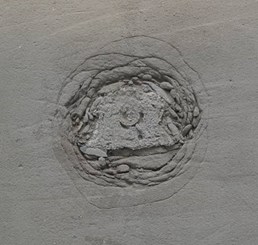
In China, a distinct zonal disintegration phenomenon was first observed and monitored in a deep tunnel at –910 m level of Dingji coalmine, and the distribution of fracture zones and non-fracture zones are displayed in Fig. 1 [21].
Fig. 1A distinct zonal disintegration phenomenon in Dingji coalmine [21]
![A distinct zonal disintegration phenomenon in Dingji coalmine [21]](https://static-01.extrica.com/articles/20619/20619-img1.jpg)
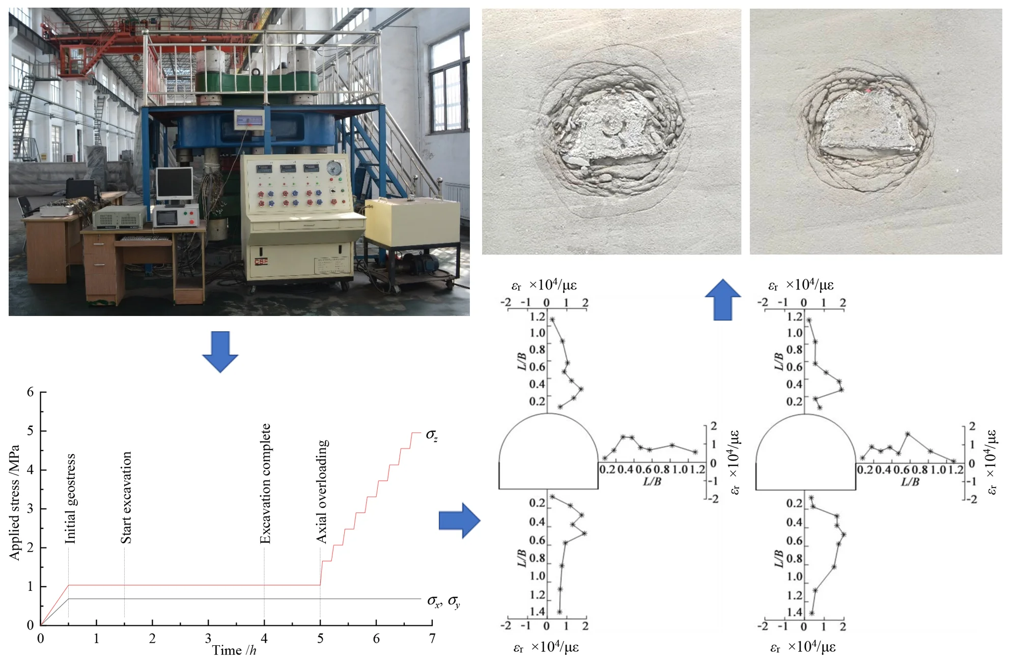
Hence, the deep tunnel at –910 m level is taken as the prototype for 3D geomechanical model tests, and capacity of deep rock breakage mechanics and supporting technique model test in State Key Laboratory of deep coal mining and environment protection, which is shown in Fig. 2, is employed to apply stress in three orthogonal directions independently.
Fig. 2Capacity of deep rock breakage mechanics and supporting technique model test in State Key Laboratory of deep coal mining and environment protection
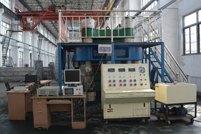
Fig. 3Schematic diagram of rectangular cemented sand model and straight wall arch tunnel (Unit: mm)
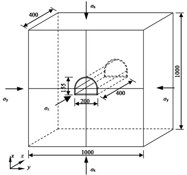
In line with the capacity of deep rock breakage mechanics and supporting technique model test, the 3D geomechanical model is a rectangular solid with both length and width of 1000 mm and height of 400 mm. Two rectangular cemented sand models with the size of 1000×1000×200 mm are manufactured and bonded together after mounting strain gauges and fracture wires.
According to the monitoring results of Li et al. [21], the height and width of deep straight wall arch tunnel in Dingji coalmine is 3880 mm and 5000 mm. Then, the height and width of straight wall arch tunnel are set as 155 mm and 200 mm in 3D geomechanical model tests, which is illustrated in Fig. 3. Therefore, geometrical similarity coefficient is set as 25.
The selection of similar material should be ahead of 3D geomechanical model tests. Cemented sand similar material, a granular cementitious material, is adopted for 3D geomechanical model tests and it is a mixture of sand, Portland cement, gypsum, and water [22, 23]. As the density of cemented sand and deep rock is 1.81 g/cm3 and 2.62 g/cm3 respectively. Hence, density similarity coefficient is 1.44. According to Froude’s similarity law, stress similarity coefficient is 36.
In 3D geomechanical model tests, two mix proportions of cemented sand similar material are adopted to simulate two strengths of deep rock, 90 MPa and 120 MPa. The corresponding uniaxial compressive strength (UCS) of cemented sand similar material is 2.48 MPa and 3.31 MPa. In 3D geomechanical model tests, rectangular cemented sand model is marked as GMT-1 for UCS of 2.48 MPa and marked as GMT-2 for UCS of 3.31 MPa. After curing 14 d, cemented sand similar material reaches the design UCS, 2.48 MPa and 3.31 MPa, then rectangular cemented sand model is put into capacity of deep rock breakage mechanics and supporting technique model test to apply the initial geostress in three orthogonal dimensions independently.
2.2. Loading procedure of 3D geomechanical model tests
According to the researches of Zuo et al. [24], Yuan et al. [16] and Gu et al. [17], the maximum principal stress parallel to the axis of deep tunnel is vital for the formation of zonal disintegration. Based on the researches of Zhang et al. [18, 25], the zonal disintegration generates when the maximum principal stress exceeds 1.5 times UCS of surrounding rock mass. Considering the UCS of cemented sand similar material, the maximum applied stress along the axial direction of excavated tunnel is set as 4.96 MPa, which is 2.0 times UCS for GMT-1 and 1.5 times UCS for GMT-2. Two 3D geomechanical model tests are carried out in a loading procedure of first loading to initial geostress, then excavating the tunnel with blasting construction, and finally overloading the stress along the axis of excavated tunnel with the stresses on the other two directions constant. The loading procedure for GMT-1 and GMT-2 is the same and is shown in Fig. 4.
Fig. 4Procedure of 3D geomechanical model test
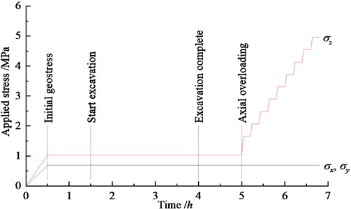
According to features of capacity of deep rock breakage mechanics and supporting technique model test, the rectangular cemented sand model is put in with the surface 1000×1000 mm side up. Seen from Fig. 3, stress is applied along the axis of excavated tunnel, stress and are applied on the vault and sidewall of excavated tunnel respectively. The burial depth of simulated tunnel is 955 m, and unit weight of rock mass is 26.2 kN/m3. Therefore, initial geostress is achieved by applying for both and and 1.5 for . Considering stress similarity coefficient, both and is equal to 0.69 MPa, and is equal to 1.04 MPa. After stabilizing the applied initial geostress about 60 min, 400 mm model straight wall arch tunnel is excavated from top to bottom by blasting excavation. After blasting excavation about 60 min, axial overloading initiates from 1.04 MPa to 4.96 MPa. Axial stress overloads in a step of 0.41 MPa after first overloading to 1.66 MPa and keeps 10 min for each step.
2.3. Blasting excavation for model tunnel
Two blasting constructions are implemented for 400 mm model tunnel with an interval of 60 min. To control the range of blasting crater, 50 mm model tunnel is digging before blasting excavation [6]. After each blasting excavation, manual digging is adopted to shape the blasting tunnel. Layout of blastholes in blasting excavation for GMT-1 and GMT-2 are shown in Fig. 5.
Fig. 5Layout of blastholes in blasting excavation (Unit: mm)
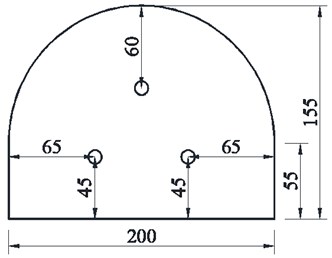
a) GMT-1
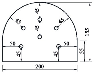
b) GMT-2
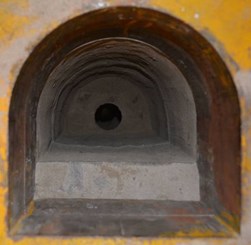
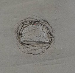
Considering the different UCS of cemented sand similar material, three vertical blastholes are drilled for GMT-1, while six vertical blastholes with central blasthole uncharged are drilled for GMT-2. During blasting excavation, each blasthole with a diameter of 10 mm and a depth of 140 mm is charged with one electric detonator and the rest length of blasthole is filled with mud [20]. Electric detonators with diameter of 6 mm and length of 35 mm are charged with 0.3 g RDX. Protective measures, such as covering with the felt and thick rubber mat, are adopted to ensure safety during blasting excavation. After blasting excavation and manual digging, the final excavated model tunnel is shown in Fig. 6.
Fig. 6Final excavated model tunnel
2.4. Arrangement of measurement points around excavated tunnel
To monitor the deformation evolution around excavated tunnel during axial overloading, both strain gauges and fracture wires [26] are arranged at the vault, sidewall, and floor of excavated model tunnel on the top surface of bottom rectangular cemented sand model, as shown in Fig. 7.
Seen from Fig. 7, there are 8 strain measuring points at the vault and right sidewall and 9 strain measuring points at the floor. The space for first 6 strain measuring points is 20 mm, then it becomes 50 mm. Each strain measuring point is mounted two BX120-5AA foil resistance strain gauges, one in radial direction, the other in tangential direction. The strain gauges are connected with two XL2010G40 high-speed static strain indicators with a sampling interval of 5 s. The 4 strain measuring points with a space of 50 mm at the left sidewall are used for collecting blasting strain signals.
Due to the existing of the strain gauges, fracture wires are placed about 10 mm away from the center line. Fracture wire is a 190 mm long slim tin foil paper. There are 20 points on each fracture wire with a space of 10 mm. Adjacent two points are in a parallel connection with an LED light in a direct-current circuit. As the resistance of slim tin foil paper is very small, the LED light is off at the beginning. When the LED light is on, it indicates a crack between two points connecting with that LED light.
Fig. 7Arrangement of strain measuring points and fracture monitoring points around the excavated tunnel
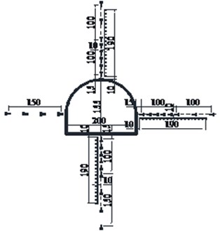
a) Schematic diagram (Unit: mm)
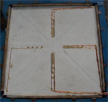
b) Physical photo
2.5. Experimental procedure of 3D geomechanical model tests
3D geomechanical model tests are carried out in the following procedure.
Firstly, make two rectangular cemented sand models with size of 1000×1000×200 mm.
Secondly, mount strain gauges and fracture wires on the top surface of bottom rectangular cemented sand model.
Thirdly, bond two rectangular cemented sand models together and put them into the capacity of deep rock breakage mechanics and supporting technique model test.
Fourthly, connect strain gauges with XL2010G40 high-speed static strain indicators and fracture wires with LED circuit.
Fifthly, apply the initial geostress to 3D geomechanical model.
Sixthly, excavate model tunnel by blasting construction.
Seventhly, overload the stress along the tunnel axis.
Finally, take out the rectangular cemented sand model and cut it to observe the fracture distribution.
3. Deformation evolution of surrounding rock during axial overloading
3.1. Strain evolution during axial overloading
Strain measuring results at point 4 of the vault for GMT-1 are taken to investigate the strain evolution during axial overloading process. Fig. 8 presents the time history of strain in both radial direction and tangential direction at point 4 of the vault. In Fig. 8, the start time is shift to zero at the beginning of axial overloading process.
Seen from Fig. 8, absolute value of strain in both radial direction and tangential direction increases with the growth of axial stress. Furthermore, strain in radial direction is a tensile strain, which indicates a tension. While strain in tangential direction is a compressive strain, which indicates a compression. Therefore, the surrounding rock around excavated tunnel is in a radial tension and circumferential compression stress state. According to the research of Wang et al. [27], when surrounding rock around the excavated tunnel in a stress state of radial tension and circumferential compression, parallel ring fracture is very easy to form and develop. Before axial stress overloading to 3.72 MPa, which is 1.5 times UCS for GMT-1, the strain variation for both radial direction and tangential direction is slow. While when axial stress exceeding 3.72 MPa, the strain variation becomes dramatic, which indicates a possible and potential ring fracture around excavated tunnel.
Fig. 8Strain evolution during axial overloading at point 4 of the vault for GMT-1
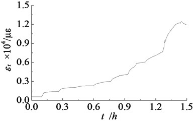
a) Radial direction
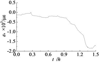
b) Tangential direction
3.2. Radial strain distribution around excavated tunnel
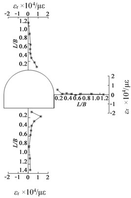
According to the research of Yuan et al. [16], the primary cause of zonal disintegration is the tension breakage in radial direction under high axial geostress. When axial stress overloading to 2.48 MPa, 3.72 MPa, and 4.96 MPa, radial strain distributions around excavated tunnel for GMT-1 are shown in Fig. 9. represents the ratio of distance between measuring point and tunnel boundary to width of excavated tunnel.
Fig. 9Radial tensile strain distribution around excavated tunnel for GMT-1
a) 2.48 MPa
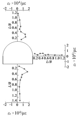
b) 3.72 MPa
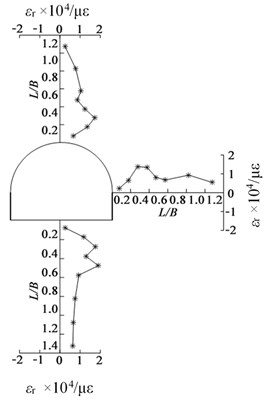
c) 4.96 MPa
Seen from Fig. 9, there are always a tension for radial strain around excavated tunnel due to the unloading effect. And radial tensile strain increase with continuous overloading of axial stress. With continuous overloading of axial stress, ring fractures appear due to large radial tensile strain. As a result of the unloading effect, the radial tensile strains near the excavated tunnel are much bigger than those away from it. For the existing free surface of excavated tunnel, the radial tensile strain at point near the boundary of excavated tunnel is small due to stress release after the appearance of first ring fracture. While in the inner part of surrounding rock, the free surface effect is weakened with the increasing distance from excavated tunnel boundary. At the end of axial overloading, an interval distribution of peaks and troughs are shown in the radial tensile strain distribution at the vault, sidewall, and floor of excavated tunnel with the increase of /. When ring fracture occurs, radial tensile strain at points in fracture zone goes through a rapid decrease due to stress release, while radial tensile strain at points near fracture zone undergoes an evident increase due to stress distribution. Therefore, peaks of radial tensile strain distribution correspond to fracture zones and troughs of radial tensile strain distribution correspond to non-fracture zones. For instance, the large radial tensile strains at point 3 and point 5 of the floor correspond to two ring fracture zones at the floor.
To investigate the influence of rock strength on zonal disintegration, radial tensile strain distribution around excavated tunnel for GMT-2 is shown in Fig. 10 when axial stress overloading to 4.96 MPa.
Fig. 10Radial tensile strain distribution around excavated tunnel for GMT-2
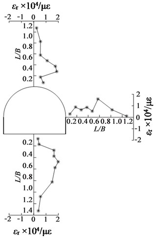
Comparing Fig. 9(c) with Fig. 10, radial tensile strain distribution for GMT-2 is a little difference with that for GMT-1. Due to the unloading effect, radial strains are all tensile strain, which indicates a radial deformation towards the excavated tunnel. Moreover, there is also an interval distribution of peaks and troughs around excavated tunnel for GMT-2. Similar with GMT-1, peaks of radial tensile strain distribution correspond to fracture zones, and troughs of radial tensile strain distribution correspond to non-fracture zones.
4. Fracture forms around excavated tunnel
The failure process around excavated tunnel is monitored by fracture wires near strain measuring points. According to the research of Xu et al. [20], fracture first occurs at the sidewall, then the floor, at last the vault during axial overloading process. In order to observe the fracture distribution around excavated tunnel directly, the rectangular cemented sand model is cut from the middle plane into a size of 700×700×200 mm, which can be seen from Fig. 11.
Seen from Fig. 11, there is a distinct zonal disintegration phenomenon with three ring fracture zones, and the fracture range of GMT-2 is smaller than that of GMT-1 due to large rock strength of cemented sand similar material for GMT-2. In order to maintain the tunnel shape and avoid the fragments pouring into excavated tunnel during axial overloading process, polyfoam is filled into the excavated tunnel after complete excavation. Due to the support of polyfoam, the shape of excavated tunnel is maintained and the fracture distribution can be observed clearly. According to Fig. 11, severe fracture occurs near the excavated tunnel boundary, while ring tensile fracture occurs away from the excavated tunnel boundary. When first ring fracture occurs around excavated tunnel, it is equivalent to a bigger excavated tunnel in deep rock mass [17]. Due to blasting damage in deep rock mass around excavated tunnel, ring fractures are much easier to happen and fractures near the excavated tunnel are more severe under high axial geostress condition [28].
Fig. 11Fracture distribution around excavated tunnel after axial overloading to 4.96 MPa
a) GMT-1
b) GMT-2
The final shape and size of excavated tunnel can be obtained by measuring the cut rectangular cemented sand model. As illustrated in Fig. 11, after axial overloading, an apparent shrinkage of excavated tunnel presents due to radial tensile deformation towards excavated tunnel. For GMT-1, the height of final excavated tunnel is only 115 mm, the width at the floor is 158 mm, and the width at the sidewall is only 117 mm. While for GMT-2, the height of final excavated tunnel is 108 mm, the width at the floor is 178 mm, and the width at the sidewall is 150 mm. Therefore, the larger the rock strength is, the smaller the tunnel shrinkage is.
Taking the excavated tunnel boundary as the measuring start, both the distance from fracture zone to tunnel boundary and fracture range can be obtained. For GMT-1, the fracture range is 113 mm below the floor, it is 96 mm up the vault, and it is 79 mm and 81 mm at the left sidewall and right sidewall respectively. For GMT-2, the fracture ranges are smaller than those for GMT-1. It is 87 mm below the floor, 55 mm up the vault, and 67 mm and 51 mm at the left sidewall and right sidewall. Hence, the larger the rock strength is, the smaller the fracture range is. After statistical analyses, the distribution characteristics of fracture zones are obtained and the radii of fracture zones around excavated tunnel is shown in Table 1.
Table 1Statistical result of fracture zones of GMT-1 and GMT-2 (Unit: mm)
Number | First fracture zone | Second fracture zone | Third fracture zone | |||
Mean radius | Mean width | Mean radius | Mean width | Mean radius | Mean width | |
GMT-1 | 108 | 16 | 150 | 25 | 192 | 2 |
GMT-2 | 110 | 20 | 141 | 5 | 165 | 2 |
Due to more electric detonators used for GMT-2, the blasting damage around excavated tunnel is more serious than that for GMT-1. Therefore, both radius and width of first fracture zone for GMT-2 is a little bigger than that for GMT-1. As illustrated in Fig. 11 and Table 1, the high the rock strength is, the smaller the radius of fracture zone is.
According to the research of Chen et al. [29], there is a scale factor among the radii of fracture zones, and radius of fracture zone is about 1.4 times bigger than that of its former fracture zone. Based on statistical result in Table 1, the radius of fracture zone is about 1.28 times bigger than that of its former fracture zone. Hence, the radius scale factor effect can be expressed as follows:
where is radius of the number fracture zone.
Due to the blasting excavation, blasting load effect not only applies a transient load on cemented sand model, but also induces many damages and cracks in cemented sand model and deteriorates its mechanical properties [20]. Moreover, blasting load plays a significant role on the first fracture zone for its rapid attenuation, and it will expand the radius and width of first fractur zone [28]. Therefore, radius scale factor, 1.28, is a little smaller than 1.4 in the research of Chen et al. [29].
5. Conclusions
With deep tunnel of Dingji coalmine as the prototype, 3D geomechanical model tests of zonal disintegration for two rock strengths are carried out via capacity of deep rock breakage mechanics and supporting technique model test in a loading procedure of first loading to initial geostress, then blasting excavation, and finally overloading along tunnel axis. Then deformation and fracture evolution during axial overloading are analyzed by strain measuring result and fracture distribution. Main conclusions are drawn as follows.
1) Due to unloading effect, radial tensile strain and tangential compressive strain present around excavated tunnel under axial geostress, which indicates a radial tension and circumferential compression stress state in surrounding rock around excavated tunnel.
2) During axial overloading process, both radial tensile strain and tangential compressive strain increase with continuous overloading of axial stress, then ring fracture appears due to large radial tensile strain. After axial overloading, an interval distribution of peaks and troughs is shown in radial tensile strain distribution around excavated tunnel.
3) By cutting the rectangular cemented sand model, a distinct zonal disintegration phenomenon with three ring tensile fractures presents after axial overloading and an apparent shrinkage of excavated tunnel also presents due to radial deformation towards excavated tunnel.
4) The larger the rock strength is, the less the tunnel shrinkage is, and the smaller the radius of fracture zone is. After statistical analysis, the radius scale factor of fracture zone in zonal disintegration is about 1.28.
References
-
Yuan L. Scientific conception of precision coal mining. Journal of China Coal Society, Vol. 42, Issue 1, 2017, p. 1-7.
-
Fairhurst C. Some challenges of deep mining. Engineering, Vol. 3, Issue 4, 2017, p. 527-537.
-
She R., Peng J. C., Huang C., Chen P. K., Li M. An overview of current status and progress in coal mining of the deep over a kilometer. China Mining Magazine, Vol. 20, Issue 7, 2011, p. 105-110.
-
Xie H. P., Ju Y., Gao M. Z., Gao F., Liu J. Z., Ren H. W., Ge S. R. Theories and technologies for in-situ fluidized mining of deep underground coal resources. Journal of China Coal Society, Vol. 43, Issue 5, 2018, p. 1210-1219.
-
Xie H. P., Gao F., Ju Y., Gao M. Z., Zhang R., Gao Y. N., Liu J. F., Xie L. Z. Quantitative definition and investigation of deep mining. Journal of China Coal Society, Vol. 40, Issue 1, 2015, p. 1-10.
-
Yuan P. Model Test on Zonal Disintegration in Deep Rock Mass under Blasting Load. Anhui University of Science and Technology, Huainan, 2016.
-
Li X., Gong F., Tao M., Dong L., Du K., Ma C., Zhou Z., Yin T. Failure mechanism and coupled static-dynamic loading theory in deep hard rock mining: A review. Journal of Rock Mechanics and Geotechnical Engineering, Vol. 9, Issue 4, 2017, p. 767-782.
-
Chen X., Li T., Xu J., Li Y. Mechanism of zonal disintegration phenomenon (ZDP) and model test validation. Theoretical and Applied Fracture Mechanics, Vol. 88, 2017, p. 39-50.
-
Yang S. Q., Chen M., Jing H. W., Chen K. F., Meng B. A case study on large deformation failure mechanism of deep soft rock roadway in Xin’An coal mine, China. Engineering Geology, Vol. 217, 2017, p. 89-101.
-
Cao R. H., Cao P., Lin H., Pu C. Z., Ou K. Mechanical behavior of brittle rock-like specimens with pre-existing fissures under uniaxial loading: experimental studies and particle mechanics approach. Rock Mechanics and Rock Engineering, Vol. 49, Issue 3, 2016, p. 763-783.
-
Zhao Y., Luo S., Wang Y., Wang W., Zhang L., Wan W. Numerical analysis of karst water inrush and a criterion for establishing the width of water-resistant rock pillars. Mine Water and the Environment, Vol. 36, Issue 4, 2017, p. 508-519.
-
Li S. C., Wang Q., Wang H. T., Jiang B., Wang D. C., Zhang B., Li Y., Ruan G. Q. Model test study on surrounding rock deformation and failure mechanism of deep roadways with thick top coal. Tunneling and Underground Space Technology, Vol. 47, 2015, p. 52-63.
-
Zhu W. S., Zhang Q. B., Li Y., Sun L. F., Zhang L., Zheng W. H. Development of large-scale geomechanical model test system under true triaxial loading and its applications. Chinese Journal of Rock Mechanics and Engineering, Vol. 29, Issue 1, 2010, p. 1-7.
-
Chen A. M., Gu J. C., Shen J., Ming Q. Z., Gu L. Y., Lu Z. Y. Application study on the geomechanical model experiment techniques. Chinese Journal of Rock Mechanics and Engineering, Vol. 23, Issue 22, 2004, p. 3785-3789.
-
Shemyakin E. I., Fisenko G. L., Kurlenya M. V., Oparin V. N., Reva V. N., Glushikhin F. P., Rozenbaum M. A., Tropp E. A., Kuznetsov Yu. S. Zonal disintegration of rocks around underground workings. Part II: Rock fracture simulated in equivalent materials. Journal of Mining Science, Vol. 22, Issue 4, 1986, p. 223-232.
-
Yuan L., Gu J. C., Xue J. H., Zhang X. Y. Model test research on the zonal disintegration in deep rock. Journal of China Coal Society, Vol. 39, Issue 6, 2014, p. 987-993.
-
Gu J. C., Gu L. Y., Chen A. M., Xu J. M., Chen W. Model test study on mechanism of layered fracture within surrounding rock of tunnels in deep stratum. Chinese Journal of Rock Mechanics and Engineering, Vol. 27, Issue 3, 2008, p. 433-438.
-
Zhang Q., Zhang X., Wang Z., Xiang W., Xue J. Failure mechanism and numerical simulation of zonal disintegration around a deep tunnel under high stress. International Journal of Rock Mechanics and Mining Sciences, Vol. 93, 2017, p. 344-355.
-
Yuan P., Xu Y., Xue J. H. Model test of anchorage deep tunnel in blasting excavation. Chinese Journal of Rock Mechanics and Engineering, Vol. 35, Issue 9, 2016, p. 1830-1836.
-
Xu Y., Yuan P. Model test of zonal disintegration in deep rock under blasting load. Chinese Journal of Rock Mechanics and Engineering, Vol. 34, Issue 2, 2015, p. 3844-3851.
-
Li S. C., Wang H. P., Qian Q. H., Li S. C., Fan Q. Z., Yuan L., Xue J. H., Zhang Q. S. In-situ monitoring research on zonal disintegration of surrounding rock mass in deep mine roadways. Chinese Journal of Rock Mechanics and Engineering, Vol. 27, Issue 8, 2008, p. 1545-1553.
-
Yuan P. Xu Y. Dynamic compressive characteristic of cemented sand similar material in uniaxial state and passive confining state. Electronic Journal of Geotechnical Engineering, Vol. 20, Issue 23, 2015, p. 11717-11728.
-
Yuan P., Xu Y. Influence of curing time to compressive properties of cemented sand similar materials. Journal of Vibration and Shock, Vol. 34, Issue 13, 2015, p. 200-204.
-
Zuo Y. J., Ma C. D., Zhu W. C., Li S. C., Gong F. Q., Chen C. C. Model test study of mechanism of layered fracture within surrounding rock of tunnels in deep stratum tunneling under dynamic disturbance. Rock and Soil Mechanics, Vol. 32, Issue 10, 2011, p. 2929-2936.
-
Zhang Q. Y., Zhang X. T., Xiang W., Chen X., Cao G., Xu X. Model test study of zonal disintegration in deep rock mass under different cavern shapes and loading conditions. Chinese Journal of Rock Mechanics and Engineering, Vol. 32, Issue 8, 2013, p. 1564-1571.
-
Zhang C., Xue J. H., Zhang X. Y., Kong F. L., Xu J. M. Research on surrounding rock fissure testing technology in geomechanical model test and its application. Chinese Journal of Rock Mechanics and Engineering, Vol. 32, Issue 7, 2013, p. 1331-1326.
-
Wang Y. M., Fan P. X., Li W. P. Mechanism of splitting and unloading failure of rock. Chinese Journal of Rock Mechanics and Engineering, Vol. 29, Issue 2, 2010, p. 234-241.
-
Yuan P., Xu Y. Zonal disintegration mechanism of deep rock masses under coupled high axial geostress and blasting load. Shock and Vibration, Vol. 2018, 2018, p. 4957917.
-
Chen X. G., Zhang Q. Y., Yang W. D., Li S. C., Liu D. J., Wang H. P. Comparative analyses of model tests and in-situ monitoring of zonal disintegration of rock mass in deep tunnels. Chinese Journal of Geotechnical Engineering, Vol. 33, Issue 1, 2011, p. 70-76.
About this article

The authors would like to thank the financial support by National Natural Science Foundation of China (No. 51174004), Anhui Provincial Natural Science Foundation (No. 1808085QE148), Project funded by China Postdoctoral Science Foundation (No. 2018M642504), Natural Science Research Project of Colleges and Universities in Anhui Province (No. KJ2017A097), Young Teacher Scientific Research Project of Anhui University of Science and Technology (No. QN201607), Doctoral Fund Project of Anhui University of Science and Technology (No. 11674). The authors also would like to thank the support of State Key Laboratory of Deep Coal Mining and Environment Protection.
