Abstract
In the present paper, the analysis for thermoelastic homogeneous isotropic microbeams has been constructed. A generalized viscothermoelasticity theory of one relaxation time with variable thermal conductivity in the context of damage mechanics definition has been applied based on simply supported conditions for aspect ratios. Laplace transform has been applied for the governing differential equations, and its inverse has been carried out by using the Tzou method. Microbeam of silicon nitride has been considered when it is subjected to ramp-type heating and simply supported. The results have been illustrated in figures to stand on the impacts of the viscothermoelastic parameter, the thermal conductivity parameter, the value of the beam thickness, and the ramp-type heating parameter. The influences of the mentioned parameters are significant on all the studied functions, and the ramp-type heating parameter plays a vital role in thermodynamically damping of the energy which has been generated on the beam.
Highlights
- An analysis for thermoelastic homogeneous isotropic microbeams has been constructed.
- A generalized viscothermoelasticity theory of one relaxation time with variable thermal conductivity in the context of damage mechanics definition has been applied.
- Microbeam of silicon nitride has been considered when it is subjected to ramp-type heating and simply supported.
- The thermal conductivity parameter, the value of the beam thickness, and the ramp-type heating parameter have significant effects on all the studied functions.
- The ramp-type heating parameter plays a vital role in thermodynamically damping of the energy which has been generated on the beam.
1. Introduction
Tzou is the first one who studied the heat conduction by solving mathematical models based on dual-phase lag (DPL) [1, 2]. Many authors and researchers applied that model in the thermal transfer applications [3-8]. The model of coupled thermoelasticity theory is one of the first types of heat conduction, which consists the equation of motion and the equation of energy conservation using the classical Fourier’s law of heat conduction [9-12]. Lord and Shulman (L-S) modified the classical Fourier’s law by inserting the relaxation time (lag time) for an isotropic body [13]. Within this model, the heat conduction law has been modified to include both heat flux and its time derivative which is called non-Fourier’s or Cattaneo’s law of heat conduction. In the context of this model, the heat equation law is a hyperbolic type of differential equation and then eliminates the paradox which coming from infinite speeds of propagation of the thermal wave [14-18].
The vibration of microbeam resonators is the most important of the micro-/nano-beam subject. Alghamdi studied the damping vibration of beam resonator with voids by dual-phase-lag generalized thermoelasticity model [9]. Sharma and Grover discussed the transverse vibrations of a homogenous isotropic and thermoelastic microscale and nanoscale beam resonators with voids [19]. Sun and Saka induced the thermal damping vibration for thermoelastic of micro-circular plate resonators [20]. They inserted a new factor in their formula of thermal damping based on Poisson's ratio, which is not the same of Lifshitz and Roukes [21]. Al-Lehaibi and Youssef studied the vibration of gold nano-beam due to thermal shock [22]. Kidawa studied the effects of internal and external damping on transverse vibrations of a microbeam due to moving heat source by using the properties of the Green functions [23]. Boley discussed the thermal vibrations of a simply supported rectangular nanobeam due to a thermal shock distributed through its span [24]. Manolis and Beskos studied the heat transfer induced vibration of microbeams structures; he used a numerical method of analysis to the thermal of the elastic dynamic response of beam structure to thermal loading [25]. Al-Huniti et al. studied the displacements and stresses of heated a bar due to a thermal wave generated by a moving laser beam with high-power [26].
Studying of viscoelastic materials or thermal and mechanical relaxations properties became vital in mechanics. The theory of viscothermoelasticity and vibrational principles have been studied in thermodynamics by Biot [27, 28]. Drozdov introduced a constitutive thermal model for the viscothermoelasticity behavior with finite strains of polymers [29]. Ezzat and El-Karmany applied a different model of viscothermoelasticity for isotropic and homogenous medium to study the influence of the thermal and mechanical relaxation of volume properties of viscothermoelastic materials [30]. Carcione et al. applied a computational algorithm for wave simulations in a thermoelastic materials by using the Kelvin-Voigt model [31]. Grover investigated the transverse vibrations in viscothermoelastic microbeams [32-34]. Sharma and Grover discussed the closed-form formulations for the transverse vibrations of a homogenous thermoelastic thin micro/nano-beam with voids [19]. Grover and Seth solved a problem of viscothermoelastic micro-scale beam resonators based on the model of dual-phase-lag (DPL) [35].
Usually, the properties of any material are constant during any process. In engineering ceramics applications, significant variations do, however, occur over the operating temperature range, in the thermal conductivity coefficient particularly. Godfrey found out that up to 45 % of decreases in the value of the thermal conductivity of different samples of silicon nitride in the range of increment (1.0 °C-400 °C). So, what are the impacts of these variations on the temperature increment, lateral deflection, stress, and energy in metal components [36]. Thus, the temperature-dependent material properties must be proposed in the analysis of thermal stress. Youssef, with many co-authors, solved many applications for thermoelastic materials with variable thermal conductivity [37-39]. Zenkour and Abbas solved a model of an infinite annular cylinder based on generalized thermoelasticity with one relaxation time for temperature-dependent properties [40].
Products typically contain many flaws in the original condition, such as microcracks or voids. Such internal holes or voids may expand and converge during a deformation cycle, whereas other content is totally removed by the development of new micro defects in stress concentrators called mechanical damage. At the latter stage, the credibility of the materials has been totally lost and macro-cracks have been created. Methane damage was graded as brittle, crawl, ductile, and fatigue according to the growing macroscopic phenomena [41].
Throughout the continuum mechanics system there is also a definition of the macros actions of the mechanically affected material. In certain cases, the principle of mechanical harm may relate the dynamics of fracture to conventional continuum mechanics. Damage variables can be introduced in different ways.
In a cross-section of the mechanically damaged medium, we thus assume an area of small element with the vector of the unit normal. The area of the defects is and the quantity of mechanical damage can be measured by the area fraction [41, 42]:
where classifies the undamaged material, while theoretically comply with the totally damaged with a complete loss of stress hold ability (fracture case). In any natural material, with values of processes taking place, which leads to a total failure. If the mechanical damage is constant through a finite area, under uniaxial tension, the relation Eq. (1) reduces to:
The effects of microcracks that are inclined to the cross-section of the materials cannot be described correctly in the same way. Correspondingly, in case of isotropic damage independent of , hence, the effective stresses are given by [41, 42]:
where are the average stresses in the undamaged material. Many applications and problems have been published under this definition of damage mechanics [42-47].
2. Basic Equations
A homogenous isotropic thermally conducting, Kelvin-Voigt type viscothermoelastic solid in Cartesian coordinate has been considered and initially undeformed at a uniform temperature . The displacement vector is defined as , and the absolute temperature is given by . The governing differential equations in the context of generalized thermoelasticity based on the non-Fourier heat conduction law will be constructed in the absence of any external body forces and heat sources as follows [34]:
The equations of motion as [2, 37]:
The heat conduction law in the form [48]:
The stress-strain constitutive equations are in the form [48]:
The deformation-displacement relations are in the form [48]:
For the viscothermoelastic materials, Lame’s parameters are in the following forms [32, 35, 49]:
where the indices , is the density, is the coefficient of linear thermal expansion, , are the viscoelastic relaxation times, is the lag time or thermal relaxation time, , Lame’s parameter in the usual case, is the thermal conductivity, and is the temperature increment.
The specific heat at constant strain satisfies the following relation [48]:
where is the diffusivity.
Consider the following mapping [48]:
where is the usual thermal conductivity.
Differentiating Eq. (10) for the coordinates , we get:
Hence, we have:
Differentiating Eq. (10) for time, we get:
Thus, the heat Eq. (5) takes the form:
3. Problem formulation
We assume small flexural deflections of a thin visco-thermoelastic nanobeam of length , with , and thickness , for which the , , and axes are defined along the longitudinal, with, and thickness directions of the beam, respectively. In equilibrium, the beam is unstrained, unstressed, without any mechanical damping, bending [6].
In this work, the well-known Euler-Bernoulli equation in one-dimensional form will be used. Thus, the displacements components are given by [32, 50, 51]:
The flexural moment of the cross-section is given by [1, 2, 9, 10, 19]:
where is the moment of inertia of the cross-section about the -axis, and is the thermal moment of the beam about the -axis which is given by [42, 50-52]:
Thus, the equation of the induced lateral deflection may be expressed in the form [32, 49]:
where is the lateral deflection, is the cross-section area.
The non-Fourier heat conduction law in Eq. (14) takes the form [32]:
and:
where is the volumetric strain which gives from Eq. (15) that:
From the relation in Eq. (8), we have the following:
and are the aggregation of the viscothermoelastic relaxation times parameters.
We consider that the thermal conductivity is a function on the temperature increment as follows [48]:
Thus, the mapping in Eq. (10) takes the form:
where is a small constant (gives the usual thermal conductivity).
Because there is no heat-flow across the upper and lower surfaces of the beam, so that . For a thin beam and assuming the temperature varies in terms of a function through the thickness direction, where , gives:
From Eq. (24) and (25), we have:
Hence, we consider that:
Then, form Eqs. (17), (18), and (25), we obtain:
Furthermore, from Eqs. (19) and (27), we get:
Thus, Eqs. (8) and (28) gives:
By carrying out the integrations, the Eq. (30) takes the form:
Multiply both sides of Eq. (29) by z and integrating for from to , then, we obtain:
where .
From Eqs. (24), (25), and (27), we have:
which gives:
Since:
Then, we can consider the following approximation:
Hence, the Eq. (31) takes the form:
For simplicity, we use the non-dimensional variables as follows [12, 37]:
where .
Hence, we have:
where:
(We dropped the prime for simplicity).
4. Formulation in the Laplace transform domain
The Laplace transform for Eq. (39) and (40), which is defined by the following formula will be applied:
where the inverse of the Laplace transform takes the form:
where Tzou [2], is the real part and is the imaginary unit, for faster convergence, many numerical applications and experiments have shown that the value of satisfies the relation.
Hence, we obtain the following system of differential equations:
During applying the Laplace transform, the following initial conditions have been used:
We can re-write the above system in Eqs. (44) and (45) to be in the forms:
where:
The system in Eqs. (49) and (50) generates the following characteristic equation:
where , , .
The solutions of the Eqs. (51) take the forms:
where , , are the roots of the characteristic equation:
To calculate the constants , 1, 2, 3, we must apply any set of boundary conditions, so we consider that the beam is thermally loaded and simply supported as following:
where is constant and is the function of the thermal loading.
Eqs. (25) and (55) gives that:
From Eqs. (33) and (57), we obtain:
Apply the Laplace transform, we have:
Then, we obtain the following system of linear equations:
After solving the above system, then, we get the solutions in the Laplace transform domain as follows:
which gives:
We get the temperature increment from Eqs. (24) and (66) as follows:
The lateral deflection is:
and the deformation takes the form:
The stress-strain energy through the beam is given by [12, 37]:
Hence, we have:
where is defined as the inversion of Laplace transform.
To get the complete solutions, we have to determine the function of the thermal loading , so, we will consider the thermal loading is ramp-type heat as follows [38]:
Hence, we have:
5. Numerical results and discussion
Now, we will consider a numerical example for which computational results are given. For this purpose, silicon nitride is taken as the thermoelastic material for which we take the following values of the different physical constants [34]: 43.5 W/(m K), 2.71×10⁻⁶ K-1, 3200 kg/m3, 293 K, 630 J/(kg K), 217×109 N/m2, 108×109 N/m2, 4.32×10⁻¹³ s, 6.89×10⁻¹³s.
The aspect ratios of the beam are fixed as and . For the microscale beam, we will assume the length of the beam is in range (1.0-100)×10-9 m , and the original time t and the relaxation time are of order 10-12 sec and 10-14 sec, respectively. The figures were carried by using the dimensionless variables for a beam with length , and .
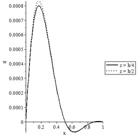
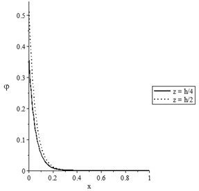
Figs. 1(a-d) represent the temperature increment, the lateral deflection, the stress, and the stress-strain energy distributions, respectively, with various values of the thermal conductivity (, ) when . It has been noted that the parameter has significant effects on the temperature increment distribution, the lateral deflection, the stress, and the stress-strain energy distributions. An increase in the value of the parameter leads to an increase in the values of the temperature increment, lateral deflection, stress, and stress-strain energy.
Fig. 1The state-functions distributions based on the thermal conductivity when t≥t0
a) The temperature increment distribution
b) The lateral deflection distribution
c) The stress distribution
d) The stress-strain energy distribution
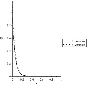
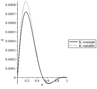
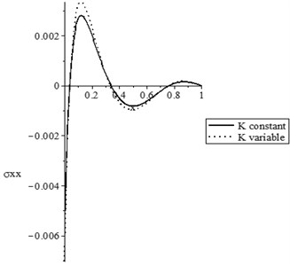
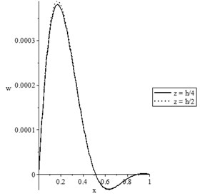
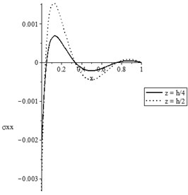
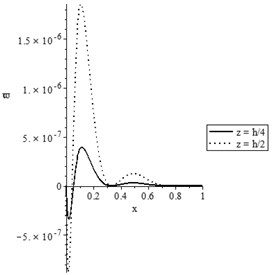
Figs. 2(a-d) show the temperature increment, lateral deflection, stress, and stress-strain energy distributions, respectively, with various values of the thermal conductivity parameter (0.0, 0.0) when . It has been noted that the parameter has a limited effect on the temperature increment distribution, while it has significant effects on the lateral deflection, the stress, and the stress-strain energy distributions. The values of the peak points of the lateral deflection, stress, and stress-strain energy increase when the thermal conductivity becomes variable.
Fig. 2The state-functions distributions based on the thermal conductivity when t<t0
a) The temperature increment distribution
b) The lateral deflection distribution
c) The stress distribution
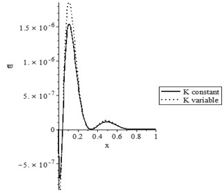
d) The stress-strain energy distribution
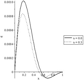
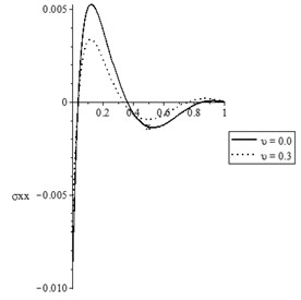
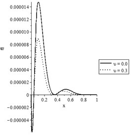
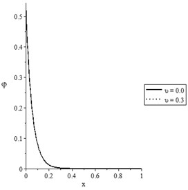
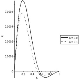
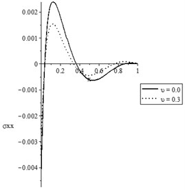
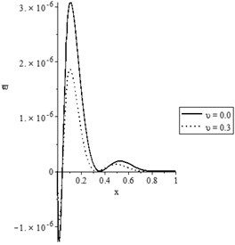
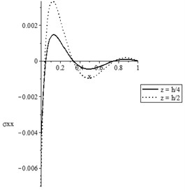
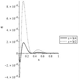
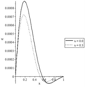
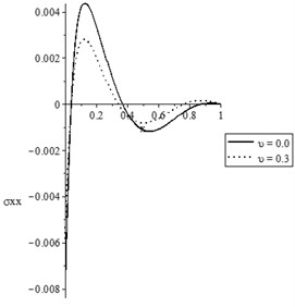
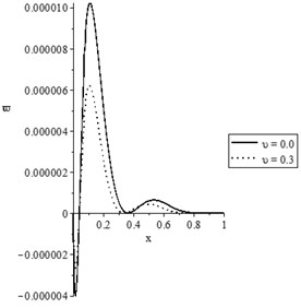
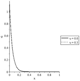
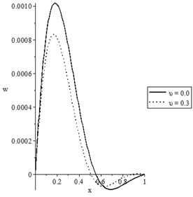
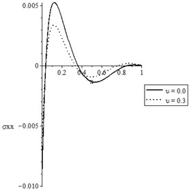
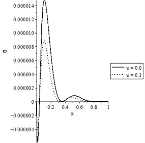
Figs. 3(a-d) and 4(a-d) show the temperature increment, lateral deflection, stress, and stress-strain energy distributions, respectively, for various values of the mechanical damage variable (0.0, 0.3) when and , respectively. It has been noted that the parameter has a limited effect on the temperature increment distribution. The mechanical damage variable has significant impacts on the lateral deflection, stress, and stress-strain energy distributions in the two cases and An increase in the value of the mechanical damage variable leads to a decrease in the values of the peak points of the lateral deflection, stress, and stress-strain energy.
Figs. 5(a-d) and 6(a-d) show the temperature increment, lateral deflection, stress, and stress-strain energy distributions, respectively, for various values of the viscothermoelastic parameter (0.0,…, 0.0) when and , respectively. It is observed that the mechanical relaxation times parameters and have a limited effect on the temperature increment distribution, while they have significant effects on the lateral deflection, stress, and stress-strain energy distributions. An increase in the values of the mechanical relaxation times parameters and leads to a decrease in the values of the peak points of the lateral deflection, stress, and stress-strain energy.
Fig. 3The state-functions distributions based on the damage mechanics variable when t≥t0

a) The temperature increment distribution
b) The lateral deflection distribution
c) The stress distribution
d) The stress-strain energy distribution
Fig. 4The state-functions distributions based on the damage mechanics variable when t<t0
a) The temperature increment distribution
b) The lateral deflection distribution
c) The stress distribution
d) The stress-strain energy distribution
Fig. 5The state-functions distributions based on the viscothermoelastic parameters when t≥t0
a) The temperature increment distribution
b) The lateral deflection distribution
c) The stress distribution
d) The stress-strain energy distribution
Fig. 6The state-functions distributions based on the viscothermoelastic parameters when t<t0
a) The temperature increment distribution
b) The lateral deflection distribution

c) The stress distribution
d) The stress-strain energy distribution
Fig. 7The state-functions distributions based on the thickness of the nanobeam when t≥t0
a) The temperature increment distribution
b) The lateral deflection distribution
c) The stress distribution
d) The stress-strain energy distribution
Fig. 8The state-functions distributions based on the thickness of the nanobeam when t<t0
a) The temperature increment distribution
b) The lateral deflection distribution
c) The stress distribution
d) The stress-strain energy distribution
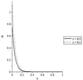
Figs. 7(a-d) and 8(a-d) show the temperature increment, lateral deflection, stress, and stress-strain energy distributions, respectively, for various values of beam’s thickness when and , respectively. It has been noted that the beam’s thickness has significant effects on the temperature increment, lateral deflection, stress, and stress-strain energy distributions.
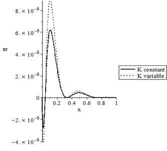
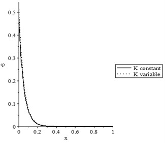
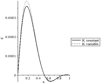
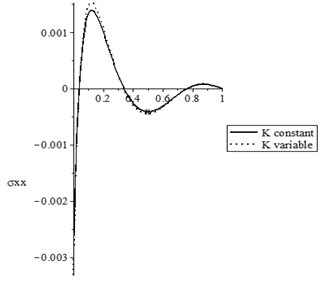
Figs. 9(a-d) and 10(a-d) show the temperature increment, lateral deflection, stress, and stress-strain energy distributions, respectively, for different values of damage mechanics parameter (0.0, 0.3) when , for constant and variable thermal conductivity, respectively. In those figures, we discuss the effect of the damage variable to the thermal conductivity.
Figs. 9(a) and 10(a) show that the values of the temperature increment based on variable thermal conductivity are higher than the values of the temperature increment based on constant thermal conductivity for the two cases of damage mechanics variable.
Fig. 9The state-functions distributions when the thermal conductivity is constant
a) The temperature increment distribution
b) The lateral deflection distribution
c) The stress distribution
d) The stress-strain energy distribution
Figs. 9(b) and 10(b) state that the values of the difference between the peak points of the lateral deflection based on the damage and non-damage situations with variable thermal conductivity are higher than the values of the difference between the peak points of the lateral deflection based on the damage and non-damage situations with constant thermal conductivity.
Fig. 9(c) and 10(c) state that the value of the difference between the peak points of the stress based on the damage and non-damage situations with variable thermal conductivity is higher than the values of the difference between the peak points of the stress based on the damage and non-damage situations with constant thermal conductivity.
Figs. 9(d) and 10(d) state that the value of the difference between the peak points of the stress-strain energy based on the damage and non-damage situations with variable thermal conductivity are higher than the values of the difference between the peak points of the stress-strain energy based on the damage and non-damage situations with constant thermal conductivity. Thus, thermal conductivity has a significant effect on the damage mechanics variable and vis versa.
Fig. 10The state-functions distributions when the thermal conductivity is variable
a) The temperature increment distribution
b) The lateral deflection distribution
c) The stress distribution
d) The stress-strain energy distribution
Fig. 1-10 show that the ramp-type heating parameter has significant effects on the temperature increment, lateral deflection, stress, and stress-strain energy. An increase the value of the ramp-time heat parameter leads to a decrease the values of all the studied functions. Thus, the ramp-time heat parameter plays a vital role in the propagation of the thermal and mechanical waves and it could be used to control the vibration of the microbeam and damping the energy generated in the beam.
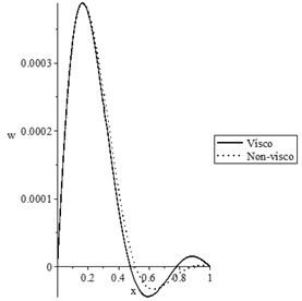
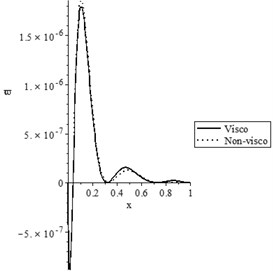
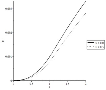
Fig. 11(a-d) represents only the lateral deflection for wide range of time and at distance when with different cases.
Fig. 11(a) shows the later deflection with respect to the thermal conductivity case, where the solid line represents the case of constant thermal conductivity while the dotted line represents the variable thermal conductivity case. It is noted that the considering of variable thermal conductivity has a significant effect on the lateral deflection distribution. Considering variable thermal conductivity leads to an increase in the value of the lateral deflection.
Fig. 11(b) shows the later deflection with various values of the mechanical damage variable, where the solid line represents the undamaged case, while the dotted line represents the damaged case. It is noted that the mechanical damage variable has a significant effect on the lateral deflection distribution. An increase in the value of mechanical damage variable leads to a decrease in the value of the lateral deflection.
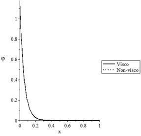
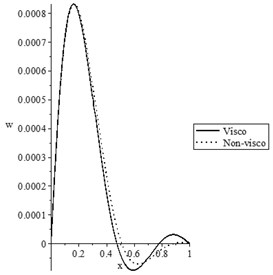
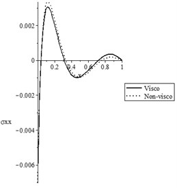
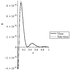
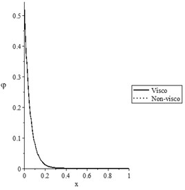
Fig. 11(c) shows the later deflection with various values of the mechanical relaxation time parameter, where the solid line represents the thermoelastic case (non-visco), while the dotted line represents the viscothermoelastic case. It is noted that the mechanical relaxation time parameter has a limited effect on the lateral deflection distribution.
Fig. 11(d) shows the later deflection with various values of the beam’s width , where the solid line represents the case of beam’s width , while the dotted line represents the case of beam’s width . It is noted that the beam’s width has a significant effect on the lateral deflection distribution. An increase in the value of leads to an increase in the value of the lateral deflection.
Fig. 11The lateral deflection for wide range of time t 0.0≤t≤2.0 and at distance x=0.2 when t0=1.0
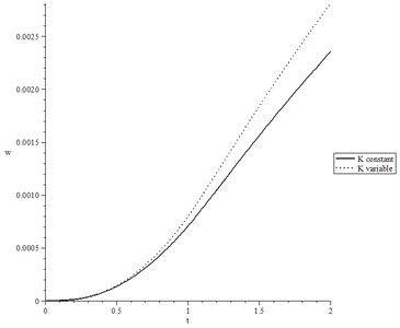
a) The lateral deflection when , , and
b) The lateral deflection when , , and
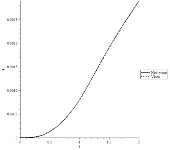
c) The lateral deflection when , , and
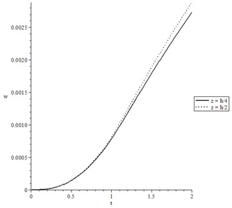
d) The lateral deflection when , , and
Overall, the results in this work agree with the results in other papers, mainly in the cases [9, 10, 12, 19, 22, 25, 32, 37].
6. Conclusions
A simply supported viscothermoelastic microbeam has been thermally loaded by ramp-type heating considering variable thermal conductivity and damage mechanics variable.
The ramp-type heating parameter, thermal conductivity, and thickness of the microbeam have significant effects, while the damage mechanics variable and the mechanical relaxation time have a limited impact on the temperature increment. The ramp-type heating parameter, thermal conductivity, thickness of the microbeam, damage mechanics variable, and mechanical relaxation time have significant effects on the lateral deflection, deformation, stress, and stress-strain energy distributions. Thus, the considering of the variability of the thermal conductivity and damage mechanics variable are more significant among studying the microbeams resonators. The thermal conductivity and damage mechanics variable between them have a significant mutual effect.
The ramp-time heat parameter can be used as a tuner to the vibration and the generated entire energy of the microbeam.
References
-
Tzou D. On the thermal shock wave induced by a moving heat source. Journal of Heat Transfer, Vol. 111, Issue 2, 1989, p. 232-238.
-
Tzou D., Transfer M.-T.-M.-H. The Lagging Behavior. Taylor Francis, Washington, 1997.
-
Xu M., Guo J., Wang L., Cheng L. Thermal wave interference as the origin of the overshooting phenomenon in dual-phase-lagging heat conduction, International Journal of Thermal Sciences, Vol. 50, Issue 5, 2011, p. 825-830.
-
Al Huniti N.-S., Al Nimr M. Thermoelastic behavior of a composite slab under a rapid dual-phase-lag heating. Journal of Thermal Stresses, Vol. 27, Issue 7, 2004, p. 607-623.
-
Ho J.-R., Kuo C.-P., Jiaung W.-S. Study of heat transfer in multilayered structure within the framework of dual-phase-lag heat conduction model using lattice Boltzmann method. International Journal of Heat and Mass Transfer, Vol. 46, Issue 1, 2003, p. 55-69.
-
Lee Y.-M., Tsai T.-W. Ultra-fast pulse-laser heating on a two-layered semi-infinite material with interfacial contact conductance. International Communications in Heat and Mass Transfer, Vol. 34, Issue 1, 2007, p. 45-51.
-
Liu K.-C. Numerical analysis of dual-phase-lag heat transfer in a layered cylinder with nonlinear interface boundary conditions. Computer Physics Communications, Vol. 177, Issue 3, 2007, p. 307-314.
-
Ramadan K. Semi-analytical solutions for the dual phase lag heat conduction in multilayered media. International Journal of Thermal Sciences, Vol. 48, Issue 1, 2009, p. 14-25.
-
Alghamdi N. Dual-phase-lagging thermoelastic damping vibration in micro-nano scale beam resonators with voids. International Journal of Multidisciplinary and Current research, Vol. 5, 2017, p. 71-78.
-
Alghamdi N. A., Youssef H. M. Dual-phase-lagging thermoelastic damping in-extensional vibration of rotating nano-ring. Microsystem Technologies, Vol. 23, Issue 10, 2017, p. 4333-4343.
-
Biot M. A. Thermoelasticity and irreversible thermodynamics. Journal of Applied Physics, Vol. 27, Issue 3, 1956, p. 240-253.
-
Youssef H. M., Alghamdi N. Thermoelastic damping in nanomechanical resonators based on two-temperature generalized thermoelasticity theory. Journal of Thermal Stresses, Vol. 38, Issue 12, 2015, p. 1345-1359.
-
Lord H. W., Shulman Y. A generalized dynamical theory of thermoelasticity. Journal of the Mechanics and Physics of Solids, Vol. 15, Issue 5, 1967, p. 299-309.
-
Dhaliwal R. S., Sherief H. H. Generalized thermoelasticity for anisotropic media. Quarterly of Applied Mathematics, Vol. 38, Issue 1, 1980, p. 1-8.
-
Hoang C. M. Thermoelastic damping depending on vibration modes of nano beam resonator. Communications in Physics, Vol. 25, Issue 4, 2015, p. 317.
-
Naik A. K., Hanay M., Hiebert W., Feng X., Roukes M. L. Towards single-molecule nanomechanical mass spectrometry. Nature Nanotechnology, Vol. 4, Issue 7, 2009, p. 445.
-
O’Connell A. D., Hofheinz M., Ansmann M., Bialczak R. C., Lenander M., Lucero E., Neeley M., Sank D., Wang H., Weides M. Quantum ground state and single-phonon control of a mechanical resonator. Nature, Vol. 464, Issue 7289, 2010, p. 697.
-
Van Beek J., Puers R. A review of MEMS oscillators for frequency reference and timing applications. Journal of Micromechanics and Microengineering, Vol. 22, Issue 1, 2011, p. 013001.
-
Sharma J., Grover D. Thermoelastic vibrations in micro-/nano-scale beam resonators with voids. Journal of Sound and Vibration, Vol. 330, Issue 12, 2011, p. 2964-2977.
-
Sun Y., Saka M. Thermoelastic damping in micro-scale circular plate resonators. Journal of Sound and Vibration, Vol. 329, Issue 3, 2010, p. 328-337.
-
Lifshitz R., Roukes M. L. Thermoelastic damping in micro-and nanomechanical systems. Physical review B, Vol. 61, Issue 8, 2000, p. 5600.
-
Al Lehaibi E.-A., Youssef H. M. Vibration of gold nano-beam with variable young’s modulus due to thermal shock. World Journal of Nano Science and Engineering, Vol. 5, Issue 4, 2015, p. 194.
-
Kidawa Kukla J. Application of the Green functions to the problem of the thermally induced vibration of a beam. Journal of Sound and Vibration, Vol. 262, Issue 4, 2003, p. 865-876.
-
Boley B. A. Approximate analyses of thermally induced vibrations of beams and plates. Journal of Applied Mechanics, Vol. 39, Issue 1, 1972, p. 212-216.
-
Manolis G., Beskos D. Thermally induced vibrations of beam structures. Computer Methods in Applied Mechanics and Engineering, Vol. 21, Issue 3, 1980, p. 337-355.
-
Al Huniti N.-S., Al Nimr M., Naji M. Dynamic response of a rod due to a moving heat source under the hyperbolic heat conduction model. Journal of Sound and Vibration, Vol. 242, Issue 4, 2001, p. 629-640.
-
Biot M. A. Theory of stress‐strain relations in anisotropic viscoelasticity and relaxation phenomena. Journal of Applied Physics, Vol. 25, Issue 11, 1954, p. 1385-1391.
-
Biot M. A. Variational principles in irreversible thermodynamics with application to viscoelasticity. Physical Review, Vol. 97, Issue 6, 1955, p. 1463.
-
Drozdov A. A constitutive model in finite thermoviscoelasticity based on the concept of transient networks. Acta Mechanica, Vol. 133, Issues 1-4, 1999, p. 13-37.
-
Ezzat M. A., El-Karamany A.-S. The relaxation effects of the volume properties of viscoelastic material in generalized thermoelasticity. International Journal of Engineering Science, Vol. 41, Issue 19, 2003, p. 2281-2298.
-
Carcione J. M., Poletto F., Gei D. 3-D wave simulation in anelastic media using the Kelvin-Voigt constitutive equation. Journal of Computational Physics, Vol. 196, Issue 1, 2004, p. 282-297.
-
Grover D. Viscothermoelastic vibrations in micro-scale beam resonators with linearly varying thickness. Canadian Journal of Physics, Vol. 90, Issue 5, 2012, p. 487-496.
-
Grover D. Damping in thin circular viscothermoelastic plate resonators. Canadian Journal of Physics, Vol. 93, Issue 12, 2015, p. 1597-1605.
-
Grover D. Transverse vibrations in micro-scale viscothermoelastic beam resonators. Archive of Applied Mechanics, Vol. 83, Issue 2, 2013, p. 303-314.
-
Grover D., Seth R. Viscothermoelastic micro-scale beam resonators based on dual-phase lagging model. Microsystem Technologies, Vol. 24, Issue 3, 2018, p. 1667-1672.
-
Claussen N., Hasselman D., Heller R. Thermal Stresses in Severe Environments. Plenum Press, New York, 1980, p. 381-95.
-
Youssef H. Vibration of gold nanobeam with variable thermal conductivity: state-space approach. Applied Nanoscience, Vol. 3, Issue 5, 2013, p. 397-407.
-
Youssef H., El Bary A. Thermal shock problem of a generalized thermoelastic layered composite material with variable thermal conductivity. Mathematical Problems in Engineering, Vol. 2006, 2006, p. 87940.
-
Youssef H. M., El-Bary A. Mathematical model for thermal shock problem of a generalized thermoelastic layered composite material with variable thermal conductivity. Computational Methods in Science and Technology, Vol. 12, Issue 2, 2006, p. 165-171.
-
Zenkour A. M., Abbas I. A. A generalized thermoelasticity problem of an annular cylinder with temperature-dependent density and material properties. International Journal of Mechanical Sciences, Vol. 84, 2014, p. 54-60.
-
Gross D., Seelig T. Fracture Mechanics: with an Introduction to Micromechanics. Springer, 2017.
-
Rezaiee Pajand M., Kazemiyan M. S., Aftabi A. S. Static damage identification of 3D and 2D frames. Mechanics Based Design of Structures and Machines, Vol. 42, Issue 1, 2014, p. 70-96.
-
Öchsner A. Continuum damage mechanics, Continuum Damage and Fracture Mechanics. Springer, 2016.
-
Voyiadjis G. Z. Handbook of Damage Mechanics: Nano to Macro Scale for Materials and Structures. Springer, 2015.
-
Yao Y., He X., Keer L. M., Fine M. E. A continuum damage mechanics-based unified creep and plasticity model for solder materials. Acta Materialia, Vol. 83, 2015, p. 160-168.
-
Voyiadjis G. Z., Kattan P. I. Introducing damage mechanics templates for the systematic and consistent formulation of holistic material damage models. Acta Mechanica, Vol. 228, Issue 3, 2017, p. 951-990.
-
Khatir A., Tehami M., Khatir S., Wahab Abdel M. Multiple damage detection and localization in beam-like and complex structures using co-ordinate modal assurance criterion combined with firefly and genetic algorithms. Journal of Vibroengineering, Vol. 18, Issue 8, 2016, p. 5063-5073.
-
Hetnarski R. B., Eslami M. R., Gladwell G. Thermal Stresses: Advanced Theory and Applications. Springer, 2009.
-
Kwok K. Shape recovery of viscoelastic beams after stowage. Mechanics Based Design of Structures and Machines, Vol. 43, Issue 1, 2015, p. 95-111.
-
Xu L., Yang Q. Multi-field coupled dynamics for a micro beam. Mechanics Based Design of Structures and Machines, Vol. 43, Issue 1, 2015, p. 57-73.
-
Sahmani S., Madyira D. M. Nonlocal strain gradient nonlinear primary resonance of micro/nano-beams made of GPL reinforced FG porous nanocomposite materials. Mechanics Based Design of Structures and Machines, 2019, https://doi.org/10.1080/15397734.2019.1695627.
-
Haskul M. Elastic state of functionally graded curved beam on the plane stress state subject to thermal load. Mechanics Based Design of Structures and Machines, 2019, https://doi.org/10.1080/15397734.2019.1660890.
Cited by
About this article

