Abstract
The exhaust devices used by snow removal vehicles are mainly based on hot-blowing snow removal. Due to the inherent characteristics of the turbojet engine such as low flow rate and high exhaust temperature, the modified hot-blowing snow removal device has problems of low snow removal efficiency and the possibility of ablation and damage to the road surface. In order to solve the problem, transforming the turbofan engine with a high flow rate and a low exhaust temperature into a hot-blowing snow removal device is an important improvement to achieve efficient and safe snow removal operations. In order to convert a medium bypass ratio turbofan engine into a hot-blowing snow removal device, the computational fluid dynamics (CFD) software CFX was used to analyze the internal and external flow field characteristics of the main nozzle of an exhaust device under the 60 % rated condition of the engine. The effective area sizes of the jet velocity and temperature predicted by the external flow field were used to optimize the layout of the main nozzle.
1. Introduction
Winter in some countries is very long and even lasts for seven or eight months a year. The large-scale snowfall has caused many inconveniences to transportation, especially air transportation, and therefore a high efficiency, low-cost and low-pollution snow removal vehicle has become the key to ensuring transportation safety. At present, the exhaust devices used by snow removal vehicles on the market are mainly based on the cold-blowing snow removal and hot-blowing snow removal. The hot snow removal device is generally modified by a turbojet engine. Its working principle is using the high-speed gas discharged by the turbojet engine to melt the snow and blow away them by the high-speed gas flow, with high efficiency, which is not only suitable for blowing the dry snow, but also for the wet snow and the ice. The cold-blowing snow removal method generally uses compressors to provide high-pressure and low-temperature airflow with high-speed flow velocity to blow away the snow. Although its cost is lower than the hot-blowing snow removal method, its structure is complex and efficiency is greatly needed to be improved with the adaptation of dry snow merely. On the whole, to achieve high-efficiency airport snow removal operations, hot snow removal is still the mainstream of current and later development. However, due to the inherent characteristics of the turbojet engine such as low flow rate and high exhaust temperature, the modified hot-blowing snow removal device has problems of low snow removal efficiency and the possibility of ablation and damage to the road surface. (The flow rate of the snow removal device generally does not exceed 60 kg/s, and the exhaust temperature reaches 600 °C). In order to solve the problem, transforming the turbofan engine with a high flow rate and a low exhaust temperature into a hot-blowing snow removal device is an important improvement to achieve efficient and safe snow removal operations, while the key point is to design a matching exhaust device.
The research on the exhaust device of hot-blowing snow removal mainly focuses on its internal and external jet characteristics. Wang et al. [1] estimated the energy required by the hot snow removal device for different snow thicknesses, which provided a basis for the selection of snow removal vehicle devices. Wang et al. [2] pointed out that when the nozzle inlet temperature is high, the variable specific heat capacity should be used for simulation according to the numerical analysis of the nozzle flow field characteristics. Nakhla and Thompson [3] calculated the trajectory of airborne debris that affects visibility during high-speed snow plowing. The results show that the trap angle of over plow deflectors should be less than 50° to eliminate snow debris blowing over top of the plow onto the windscreen. Eskridge and Thompson [4] calculated the flow around trucks. The results show that the fine snow particles can be entrained in a wake that extends several vehicle heights downstream. Zhang et al. [5] used software FLUENT to numerically simulate the flow field of the jet pipe from a snow removal vehicle, and proved that when the compressed high-speed air flow passes through the pipe and reaches the exhaust port, its jet velocity meets the snow removal requirements. Li et al. [6] conducted a numerical simulation on the flow field characteristics of a rectangular nozzle under three flow states: subsonic, supersonic and static based on the Frave average N-S equation and B-L turbulence model. Feng et al. [7] used software FLUENT to numerically simulate the external flow field of four rectangular nozzles with aspect ratios of 1, 2, 4, and 8, and pointed out that the rectangular nozzle with a large aspect ratio has obvious advantages in reducing the infrared radiation of the high temperature plume. King and Dujmovic [8] investigated the impact of snowflakes on the windshields by solving the potential flow equations. Results show that the inertia of the snow affects the likelihood of impact on the windshield and that an optimum exists at a speed, where a balance exists between aerodynamic and inertial forces. Thompson and Nakhla [9] show that the maximum amount of the snow debris blows over top of the plow with the plow blade normal to the direction of travel. Zhang et al. [10] conducted an experimental study on the Reynolds stress on the jet symmetry plane of different round-turned rectangular convergent nozzles and axisymmetric nozzles, and pointed out that with the increase of the aspect ratio, both the swirling intensity and Reynolds stresses of the rectangular nozzle jet increase accordingly.
Based on the heat exchange between the high-temperature jet from the snow removal vehicle and the snow which can melt the snow, Rayleigh [11] used the two-phase flow theory to analyze its external flow field. The research results show that even at lower speeds, the slender jet will eventually break into droplets due to instability. Therefore, the jet instability theory is proposed, but the viscous effect of air and liquid is not considered in this work. Qureshi et al [12] studied the influence of the aspect ratio of the rectangular nozzle on the jet characteristics in the liquid-gas-solid three-phase flow and the interaction between the different phases. The Euler two-fluid model was used to simulate the gas-solid flow, and the Lagrange trajectory method was adopted to track the spray jet. According to the results, under the same flow conditions, the aspect ratio has a significant effect on the jet length and trajectory. Under the same nozzle spray area, a vertically oriented rectangular nozzle (that is, a nozzle with an aspect ratio of less than 1) has a deeper penetration than a horizontally oriented rectangular nozzle (that is, a nozzle with an aspect ratio of greater than 1) Mohamed et al. [13] used numerical methods to study the formation and development mechanism of cavitation inside the nozzle by changing the shape of the nozzle. The results show that the strength of cavitation is directly related to the shape of the nozzle. The cavitation strength of the sharp edges, slanted edges and curved edges decreases gradually. For a rectangular nozzle with an aspect ratio of 5, Rembold et al. [14] utilized numerical methods to study the evolution process of the jet entering a static environment when the ejection Mach number is 0.5. The results illustrated that the asymmetry of the velocity distribution of the exit jet with respect to the jet axis causes the jet to rapidly diffuse along its short axis in the so-called characteristic region. For circular nozzles with the same equivalent diameter and non-circular nozzles (including ellipse, rectangle, and triangle with aspect ratios of 1:1 and 2:1), Miller et al. [15] studied the spatial development process of the three-dimensional jet at the outlet through numerical simulation. Visualized flow results show that large-scale coherent structures are formed in both angular jets and non-angular jets. At the same time, all non-circular nozzles show a better mixing effect than circular nozzles, and the mixing effect of the isosceles triangular nozzle is optimal.
Based on the universal computational fluid dynamics software CFX, a simulation is conducted on the internal and external flow fields of the main nozzle of a hot-blowing snow removal exhaust device modified by a turbofan engine with a medium bypass ratio in this paper. To obtain the best jet characteristics, the velocity field and temperature field of the exit jet are optimized from the perspective of structural parameters.
2. Working status analysis
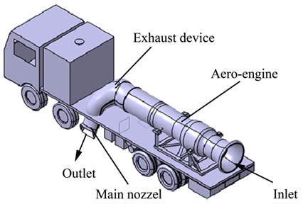
Fig. 1 shows the schematic diagram of hot-blowing snow removal device, which is composed of a car, a turbo-fan aero-engine installed on the chassis, an air intake component, an exhaust device, a starting system, a fuel supply system, and a control system. When the snow removal vehicle is working, air will enter the aero-engine from the intake component, and then the high-speed and high-temperature gas flows out exhaust device. Therefore, the snow and ice grounded on both sides of the vehicle body will be removed with the help of the gas from the main nozzles. In addition, the blowing distance of the gas on one side can reach tens of meters. When the aero-engine remains in the same state, the cross-sectional shape, the outlet inclination angle, and the height above the ground of the main nozzle all have effects on the speed and temperature distribution of the jet diffusion, which in turn affects the snow blowing effect. For this reason, the influence of the above-mentioned nozzle structural parameters on the jet flow have been simulated and optimized to achieve the best snow blowing effect.
Fig. 1The schematic diagram of the hot-blowing snow removal device
According to the Ref [16], check the performance parameters of a certain type of medium bypass ratio turbofan engine under the 60 % rated condition, where the bypass ratio is 2.48, the total air flow is 185kg/s, the internal temperature is 708 K, and the external culvert temperature is 338 K, total turbine inlet pressure is 12.5 atm, turbine drop pressure ratio is 7, external culvert pressure is 1.8 atm. According to the relationship between the bypass ratio and the total air flow, the air flow of the inner and external ducts can be determined. The specific relationship can be expressed as:
where is the bypass ratio; is the total air flow; and are the external and inner culvert air flow respectively.
According to the inner and outer culvert air flow, inner and outer culvert temperature, and ideal gas energy conservation theory, the outlet temperature of the inner and outer culvert mixer (that is, the total temperature of the exhaust device inlet) can be determined. The specific calculation formula can be expressed as:
where , , are the inner culvert temperature, the outer culvert temperature, and the outlet temperature of the inner and outer culvert mixer, respectively.
According to the inlet total pressure and the expansion ratio of the turbine, the total turbine outlet pressure can be determined. Substitute the total turbine outlet pressure and the external culvert pressure into the mixer pressure characteristic diagram in the reference [11] to determine the outlet pressure of the mixer, i.e. the inlet total pressure of the exhaust device. Based on the calculation theory of one-dimensional pipe flow, the outlet flow state of the exhaust device is determined, and the specific calculation formula can be expressed as:
where ; is the exit area of the tail nozzle; is the non-dimensional dense flow.
After calculation, for the rated working state being 0.6, , indicating that the nozzle is in an over-expanded state at this time. Therefore, when the outlet area of the main nozzle of the modified hot-blowing snow removal exhaust device is the same as that of the turbofan engine exhaust device, the outlet static pressure of the main nozzle of the hot-blowing snow removal exhaust device at this time is the atmospheric pressure. After calculation, the inlet and outlet boundary conditions of the main nozzle of the hot-blowing snow removal exhaust device in the 60 % rated condition are shown in Table 1. It should be noted that although thermal snow removal devices generally include a main nozzle for the main snow removal function and a front nozzle for the auxiliary snow removal function (mainly used for snow removal under the car body), the flow rate of the opening nozzle is much smaller than that of the main nozzle. Therefore, the influence of the opening nozzle on the flow state of the main nozzle is not considered.
Table 1The inlet and outlet boundary conditions
Boundary parameter | Values |
Total inlet temperature (K) | 444.3 |
Total inlet pressure (atm) | 1.7 |
Outlet static pressure (atm) | 1.0 |
3. Simulation of flow characteristics
Determine the size of the main nozzle of the exhaust device according to the overall size of the snow removal vehicle, and use three-dimensional modeling software to design its size. The inlet size of the main nozzle is the inlet size of the original exhaust section of the turbofan engine (0.83 m2). Seven different outlet sections of the main nozzle with the same cross-sectional area being 0.395 m2 are designed for testing, including circular section, square section, 1.25:1 rectangular section, 1.5:1 rectangular section, 1.75:1 rectangular section, 2:1 rectangular section, and 2.5:1 rectangular section. Moreover, in order to ensure the interchangeability of different outlet sections of main nozzles, the adaptive tubes between the main nozzles and the outlets with the same length (generally less than 200 mm in length) are designed specially, where the inlets are the circular section with the same area, and the outlets are circular section or rectangular sections with different aspect ratios. The three-dimensional solid models of the main nozzle with a circular outlet section and a square outlet section are shown in Fig. 2.
Fig. 2Three-dimensional models of the main nozzle with different outlet sections (0.395 m2)
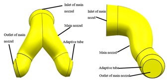
a) Circular outlet section
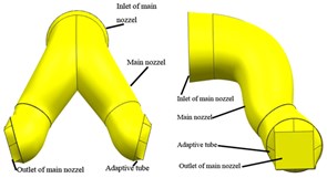
b) Square outlet section
The internal flow field of the main nozzle of the exhaust device with different exit cross-sectional shapes has meshed, where is equal to 10 to meet the requirements of the - turbulence model in the simulation of the flow field. According to the mesh requirements of the nozzle jet in the reference [17], the flow field has meshed. Use the general computational fluid dynamics software CFX to simulate the internal flow field of the main nozzle of the exhaust device. The inlet boundary is the total temperature and total pressure, and the outlet boundary is the average static pressure, as shown in Table 1. And the main nozzle wall is adiabatic and smooth without slippage. Table 2 shows the simulation of the average total pressure, velocity and static temperature at the outlet of the main nozzle for different outlet cross-sectional shapes.
Table 2The characteristic parameters of the main nozzle outlet
Outlet cross-sectional shape | Average total pressure / Pa | Average velocity /m/s | Average static temperature / K |
Circular section | 169123 | 338.47 | 394.14 |
Square section | 168533 | 335.80 | 394.77 |
1.5:1 Rectangular section | 168856 | 339.73 | 393.92 |
2:1 Rectangular section | 168185 | 336.81 | 394.80 |
2.5:1 Rectangular section | 168617 | 340.06 | 393.51 |
It can be seen from Table 2 that different outlet cross-sectional shapes have little effect on the overall performance parameters of the main nozzle. Therefore, in the optimization simulation of different structural parameters below, the relevant parameters in Table 3 can be directly used to calculate the external flow field without further internal flow field simulation.
Fig. 3 shows the exit velocity distribution of the main nozzle when a circular exit section and a 1.5:1 rectangular exit section are used. According to Fig. 2, compared to the circular exit section, the size of the core high-speed zone of the rectangular exit section is larger, and as the aspect ratio of the exit section increases, the core high-speed zone is elongated, but the length of the low-speed zone near the bottom also increases. Therefore, it can be considered that as the cross-sectional aspect ratio increases, the width of the effective area of the nozzle jet increases, but the velocity dead zone (For the different standards of the effective velocity and temperature, if the values of velocity and temperature are lower than the standards, this zone will be defined as dead zone.) may also increase accordingly. Since the total temperature in the main nozzle flow is approximately constant, the static temperature distribution of the outlet section is opposite to the velocity distribution and is not separately given here.
Considering the accuracy and efficiency in calculating the external flow field of the main nozzle, the adaptive tube is horizontally extended to 200 mm, and the external flow field is a square domain of 50 m×50 m×25 m. The adaptive tube and the external flow field are respectively divided into grids, and the settings of and the grid density are consistent with those of the internal flow field.
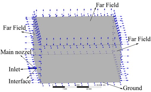
Fig. 4 shows the computational domain and boundary conditions when simulating the external flow field of the main nozzle. The details are as follows: the boundary conditions of the adaptive tube inlet of the main nozzle are set to the total temperature and total pressure with the specific values shown in Table 2; the ground and the main nozzle wall are adiabatic, non-slip, and smooth; the other five interfaces adopt pressure far-field boundary; the outlet of the adaptive tube and the inlet of the external flow field are set as the internal interface. It should be pointed out that for the following parameter optimization analysis, only the shape of the computational domain is fine-tuned, while the boundary conditions remain unchanged.
Fig. 3The velocity distribution of the main nozzle outlet
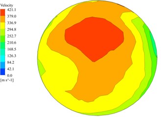
a) Circular exit section
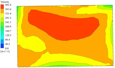
b) 1.5:1 rectangular exit section
Fig. 4Computational domain and boundary condition of the external flow field
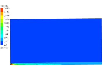
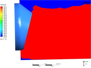
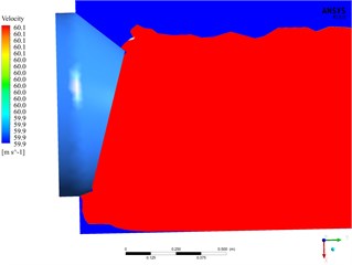
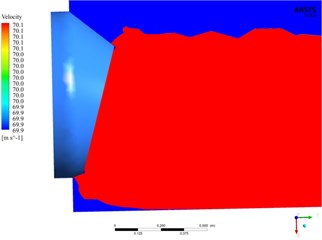
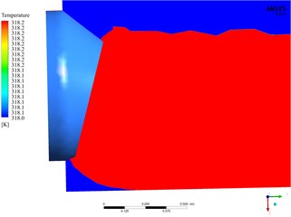
Based on the circular section outlet with the distance being 200 mm from the outlet section to the ground, the external flow field of the main nozzle with the outlet inclination angle being 15° is analyzed. Fig. 5 shows the axial and longitudinal distribution of jet velocity in the external flow field of the main nozzle. It can be seen from Fig. 5(a) that when the standard of the speed effective zone is 60 m/s, the length of the single-sided jet can reach 30 m, which meets the snow removal requirement for airport runway with the width of 60 m. According to Fig. 5(b), when the effective zone velocity is 60 m/s, the jet height can reach 1.2 m. Fig. 6 shows the axial and longitudinal distribution of jet temperature in the external flow field of the main nozzle. According to Fig. 6(a), when the standard of the effective temperature zone is 318 K, the length of the single-sided jet can reach 30 m, which meets the snow removal requirement for the airport runway with a width of 60 m. According to Fig. 6(b), when the standard of the effective temperature zone is 318 K, the jet height can reach 1 m. Based on the predicted speed and the length and height of the effective temperature zone, it can be considered that the design of the main nozzle meets the snow removal requirements for the hot-blowing snow removal device modified from the turbofan engine under the 60 % rated condition.
It should be noted that since the inclination angle of the outlet section of the main nozzle is 15°, there will be a local velocity and temperature dead zone at its outlet. By analyzing the size of the dead zone under different speed and temperature standards, it can be seen that: (1) When the speed standard is less than 40 m/s, the size of the dead zone, which results from the height of the nozzle from the ground and the outlet inclination, is smaller because the outlet jet drives the surrounding air and fills up the local dead zone. However, due to the limited kinetic energy of the exit jet, the velocity dead zone gradually appears after the velocity standard over 50 m/s, and as the velocity standard increases, the length and height of the velocity dead zone increase accordingly. (2) Because the jet temperature of the main nozzle is not high and decays quickly (the outlet jet temperature is lower to avoid ablation of the tube surface), the temperature dead zone always exists. And as the temperature standard increases, the length and height of the temperature dead zone also increase accordingly. Moreover, the length and height basically conform to the Pythagorean theorem. Fig. 7(a) and (b) show the dead zone distribution of the exit jet with the speed standard being 70 m/s and with the temperature standard being 333 K, respectively.
Fig. 5The velocity distribution of the external flow field
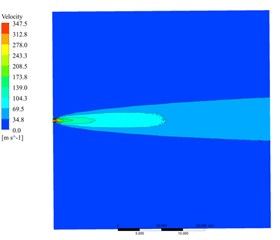
a) Axial distribution
b) Longitudinal distribution
Fig. 6The Temperature distribution of the external flow field
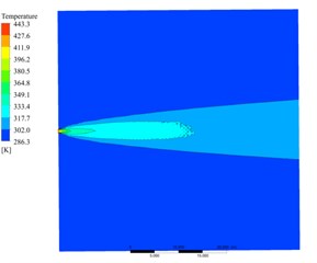
a) Axial distribution
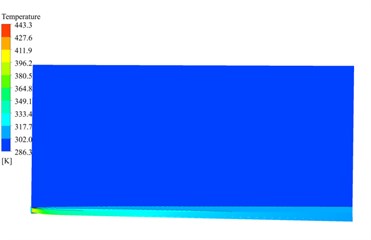
b) Longitudinal distribution
4. Optimization analysis
On the basis of the reference nozzle in Section 3, the jet characteristics of the main nozzle are optimized from the following three aspects: the height from the outlet section of the main nozzle to the ground, the outlet inclination angle, and the outlet section shape.
4.1. Optimal analysis of jet characteristics affected by the height to ground
Due to the height limitation of the vehicle body chassis, the height of the outlet section of the main nozzle from the ground is generally 150-200 mm. Therefore, the following analysis of the jet characteristics for the main nozzle is carried out at the distance of 150 mm and 200 mm. Table 3 and Table 4 respectively give the effective zone size and dead zone size at the height of 150 mm and 200 mm under different speeds (30 m/s, 40 m/s, 50 m/s, 60 m/s, 70 m/s) and different temperatures (318 K, 333 K, 343 K), respectively.
Fig. 7The dead zone distribution of the outlet jet under different standards
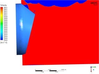
a) The speed standard 30 m/s
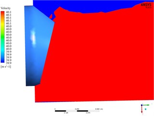
b) The speed standard 40 m/s
c) The speed standard 50 m/s
d) The speed standard 60 m/s
e) The speed standard 70 m/s
f) The temperature standard 318 K
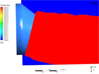
g) The temperature standard 333 K
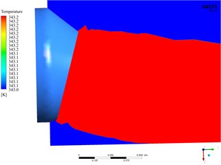
h) The temperature standard 343 K
According to Table 3, for the two heights from the ground, when the effective zone speed standard is 60 m/s, the single-side jet length of the main nozzle can reach 30 m, which meets the snow removal requirements for the airport runway with a width of 60 m. Notably, when the lengths of effective areas are longer than 30 m, the lengths in Table 3 are still chosen as 30 m, and the widths of the effective zone are measured at the length of 30 m. When the lengths of effective areas are shorter than 30 m, the lengths in Table 3 would be chosen as the real length, and the widths of the effective zone are measured at the corresponding length. The single-side jet length is less than 30 m only at 70 m/s, but it can still reach about 25 m, indicating that the hot-blowing snow removal device modified by the turbofan engine meets the snow removal requirements. Moreover, the width of the speed effective area at the height of 200 mm is larger than that at the height of 150 mm. By analyzing the size of the dead zone under different speed standards, it can be concluded that the length and width of the dead zone are larger at the height of 200 mm. However, the size of the dead zone is relatively close and small below the speed of 50 m/s both at the height of 150 mm and 200 mm. It can be seen from Table 4 that the size of the effective area is relatively similar at the height of 150 mm and 200 mm under different temperature standards. When the temperature standards are 318 K, 333 K, and 343 K, the length of the effective temperature zone of the single-sided jet can reach 30 m, 10 m, and 5 m, respectively. Meanwhile, the height has a consistent influence on the size of the temperature dead zone and the speed dead zone. In general, at the speed standard of 50 m/s (existing hot-blowing snow removal data shows that at the exit jet velocity of 50 m/s, the snow removal requirements for runway can be satisfied), the jet effect and the vehicle pass ability are better at the height of 200 mm.
Table 3The size of the velocity effective zone and dead zone at different heights from the ground
Speed standard / m·s-1 | Height / mm | Effective area | Dead zone | ||
Length / m | Width / m | Length / m | Width / m | ||
30 | 150 | 30.00 | 8.11 | 0.32 | 0.01 |
200 | 30.00 | 8.49 | 0.32 | 0.01 | |
40 | 150 | 30.00 | 6.98 | 0.34 | 0.02 |
200 | 30.00 | 7.36 | 0.43 | 0.01 | |
50 | 150 | 30.00 | 5.66 | 0.47 | 0.06 |
200 | 30.00 | 6.04 | 0.51 | 0.07 | |
60 | 150 | 30.00 | 4.15 | 0.56 | 0.09 |
200 | 30.00 | 4.34 | 0.56 | 0.18 | |
70 | 150 | 24.53 | 3.02 | 0.64 | 0.15 |
200 | 25.09 | 3.30 | 0.64 | 0.18 | |
Table 4The size of the temperature effective zone and dead zone at different heights from the ground
Temperature standard / K | Height / mm | Effective area | Dead zone | ||
Length / m | Width / m | Length / m | Width / m | ||
318 | 150 | 30.00 | 3.58 | 0.38 | 0.17 |
200 | 30.00 | 3.77 | 0.41 | 0.18 | |
333 | 150 | 10.19 | 1.32 | 0.56 | 0.17 |
200 | 10.00 | 1.60 | 0.60 | 0.19 | |
343 | 150 | 5.09 | 0.94 | 0.71 | 0.17 |
200 | 5.66 | 0.94 | 0.75 | 0.19 | |
4.2. Optimal analysis of jet characteristics affected by outlet inclination angle
According to the structural limitation to the outlet inclination angle of the main nozzle from the hot-blowing snow removal device and the jet flow simulation in Section 4.1, inclination angles of 10°, 12.5°, 15° and 17.5° are selected to implement the optimal analysis for the jet characteristics.
Table 5 and Table 6 give the size of the effective zone and dead zone of the velocity and temperature at different outlet inclination angles. As illustrated in Table 5, for different outlet inclination angles, the single-sided jet length of the main nozzle can reach 30 m at the speed standard of 60 m/s in the effective zone, and only at 70 m/s, the length of the single-sided jet is less than 30 m but increases with the decline of inclination angle. With the increase of the inclination angle, when the speed standard is less than 50 m/s, the width of the effective area increases monotonously, and when the speed standard is greater than 50 m/s, the width of the effective area shows a decreasing trend. At the same time, with the increase of the outlet inclination angle, the length of the dead zone shows a monotonous decrease. As for the width of the dead zone, when the speed standard is less than 50 m/s, it first decreases and then increases, and at 15° is the smallest. As shown in Table 6, with the increase of the outlet inclination angle, the length and width of the temperature effective zone decrease slightly, while the length of the temperature dead zone shows a trend of first decreasing and then increasing, and the minimum is at 15°. It is worth noting that the outlet inclination angle has little effect on the width of the temperature dead zone. In general, the jet effect is better at the speed standard of 50 m/s and at the outlet inclination angle of 15°.
Table 5The size of the after velocity effective zone and dead zone at different nozzle angles
Speed standard / m·s-1 | Inclination angle / ° | Effective area | Dead zone | ||
Length / m | Width / m | Length / m | Width / m | ||
30 | 10.0 | 30.00 | 7.55 | 0.43 | 0.01 |
12.5 | 30.00 | 7.92 | 0.34 | 0.01 | |
15.0 | 30.00 | 8.49 | 0.32 | 0.01 | |
17.5 | 30.00 | 8.68 | 0.26 | 0.03 | |
40 | 10.0 | 30.00 | 6.6 | 0.47 | 0.05 |
12.5 | 30.00 | 6.79 | 0.45 | 0.04 | |
15.0 | 30.00 | 7.36 | 0.43 | 0.01 | |
17.5 | 30.00 | 7.55 | 0.41 | 0.09 | |
50 | 10.0 | 30.00 | 5.66 | 0.6 | 0.09 |
12.5 | 30.00 | 5.85 | 0.56 | 0.09 | |
15.0 | 30.00 | 6.04 | 0.51 | 0.07 | |
17.5 | 30.00 | 6.04 | 0.47 | 0.18 | |
60 | 10.0 | 30.00 | 4.72 | 0.68 | 0.19 |
12.5 | 30.00 | 4.53 | 0.64 | 0.18 | |
15.0 | 30.00 | 4.34 | 0.56 | 0.18 | |
17.5 | 30.00 | 4.15 | 0.51 | 0.18 | |
70 | 10.0 | 27.36 | 3.21 | 0.73 | 0.19 |
12.5 | 26.42 | 3.21 | 0.71 | 0.18 | |
15.0 | 25.09 | 3.3 | 0.64 | 0.18 | |
17.5 | 23.58 | 2.83 | 0.56 | 0.18 | |
Table 6The size of the temperature effective zone and dead zone at different nozzle angles
Temperature standard / K | Inclination angle / ° | Effective area | Dead zone | |||
Length / m | Width / m | Length / m | Width / m | |||
318 | 10.0 | 30 | 4.15 | 0.56 | 0.19 | |
12.5 | 30 | 4.15 | 0.45 | 0.18 | ||
15.0 | 30 | 3.77 | 0.41 | 0.18 | ||
17.5 | 30 | 3.21 | 0.47 | 0.18 | ||
333 | 10.0 | 12.26 | 1.51 | 0.73 | 0.19 | |
12.5 | 11.32 | 1.51 | 0.71 | 0.19 | ||
15.0 | 10 | 1.6 | 0.6 | 0.19 | ||
17.5 | 9.43 | 1.51 | 0.62 | 0.19 | ||
343 | 10.0 | 6.23 | 1.13 | 0.9 | 0.2 | |
12.5 | 6.04 | 0.94 | 0.88 | 0.2 | ||
15.0 | 5.66 | 0.94 | 0.75 | 0.19 | ||
17.5 | 5.28 | 0.94 | 0.77 | 0.2 | ||
4.3. Optimal analysis of jet characteristics affected by outlet section shape
According to the optimization results of the height from the ground and the outlet inclination angle, the height and the outlet inclination angle is selected as 200 mm and 15° respectively to make the effect comparison of seven different nozzle outlet section shapes on the jet characteristics, including circular section, square section, 1.25:1 rectangular section, 1.5:1 rectangular section, 1.75:1 rectangular section, 2:1 rectangular section, and 2.5:1 rectangular section.
Table 7The size of the velocity effective zone for different outlet section shape under various velocity standards
Speed standard / m·s-1 | Outlet cross-sectional shape | Effective area | |
Length / m | Width / m | ||
30 | Circular Section | 30.00 | 8.49 |
Square Section | 30.00 | 8.68 | |
1.25:1 Rectangular Section | 30.00 | 8.87 | |
1.5:1 Rectangular Section | 30.00 | 10.38 | |
1.75:1 Rectangular Section | 30.00 | 11.70 | |
2:1 Rectangular Section | 30.00 | 13.58 | |
2.5:1 Rectangular Section | 30.00 | 18.49 | |
40 | Circular Section | 30.00 | 7.36 |
Square Section | 30.00 | 7.55 | |
1.25:1 Rectangular Section | 30.00 | 7.74 | |
1.5:1 Rectangular Section | 30.00 | 9.06 | |
1.75:1 Rectangular Section | 30.00 | 10.00 | |
2:1 Rectangular Section | 30.00 | 11.32 | |
2.5:1 Rectangular Section | 19.81 | 12.45 | |
50 | Circular Section | 30.00 | 6.04 |
Square Section | 30.00 | 6.23 | |
1.25:1 Rectangular Section | 30.00 | 6.42 | |
1.5:1 Rectangular Section | 30.00 | 6.79 | |
1.75:1 Rectangular Section | 27.92 | 7.17 | |
2:1 Rectangular Section | 22.64 | 7.74 | |
2.5:1 Rectangular Section | 13.21 | 7.74 | |
60 | Circular Section | 30.00 | 4.34 |
Square Section | 30.00 | 4.34 | |
1.25:1 Rectangular Section | 30.00 | 3.77 | |
1.5:1 Rectangular Section | 24.91 | 4.72 | |
1.75:1 Rectangular Section | 19.81 | 7.17 | |
2:1 Rectangular Section | 16.04 | 5.28 | |
2.5:1 Rectangular Section | 9.43 | 5.09 | |
70 | Circular Section | 25.09 | 3.30 |
Square Section | 23.58 | 3.30 | |
1.25:1 Rectangular Section | 21.69 | 3.36 | |
1.5:1 Rectangular Section | 18.49 | 3.40 | |
1.75:1 Rectangular Section | 14.34 | 3.21 | |
2:1 Rectangular Section | 11.69 | 3.21 | |
2.5:1 Rectangular Section | 6.23 | 3.21 | |
Table 7 shows the size of the velocity effective zone at different outlet section shape under different velocity standards. As displayed in Table 7, when the speed standard is less than 40 m/s, with the increase in the aspect ratio of the outlet section, the lengths of the speed effective zones do not change greatly, but the widths increase. When the speed standards are 50 m/s and 60 m/s, the lengths of the speed effective zones are still 30 m for the circular section, square section and 1:1.25 rectangular sections, and for the other outlet sections, the lengths decrease quickly and the widths remain basically unchanged. When the speed standards is 70 m/s, the lengths of the speed effective zones are all less than 30 m, and with the increase in the aspect ratio of the outlet section, the lengths of the speed effective zones decrease seriously. In addition, the width of the airport runway is 60 m, the lengths of the effective areas equal to 30 m can meet snow removal requirements for the entire runway. Hence, when the lengths of effective areas are shorter than 30 m, the speed dead zone will be occurred. In general, jets under the 1.25:1 rectangular section and 1.5:1 rectangular section are better, and the size of the speed dead zone is smaller at the speed standard of 50 m/s.
Table 8 shows the size of the effective temperature zone predicted by different outlet section shape under different temperature standards. According to Table 8, when the temperature standard increases from 318 K to 343 K, the lengths and widths of the effective temperature zones decrease obviously. In addition, the length of the effective temperature zone for the temperature standard 318 K is almost twice longer than that of the 333 K, and four times longer than that of the 343 K. As the aspect ratio of the outlet section increases, the lengths of the temperature effective zones decrease rapidly, while the widths increase slightly, and the influence of the aspect ratio is more obvious when the temperature standard is higher. In general, the size of the effective temperature zones of the circular outlet section and the square outlet section is the largest, followed by the 1.25:1 rectangular section. When the aspect ratio is greater than 1.5:1, the temperature effective zone attenuates extremely. Therefore, considering the size of the velocity and temperature effective zones comprehensively under different outlet section shapes, it can be considered that the jet with a 1.25:1 rectangular section has the best effect.
Table 8The size of the temperature effective zone for different outlet section shape under various temperature standards
Temperature standard / K | Outlet cross-sectional shape | Effective area | |
Length / m | Width / m | ||
318 | Circular Section | 30.00 | 3.77 |
Square Section | 27.74 | 3.77 | |
1.25:1 Rectangular Section | 26.42 | 3.77 | |
1.5:1 Rectangular Section | 21.70 | 3.96 | |
1.75:1 Rectangular Section | 16.04 | 4.15 | |
2:1 Rectangular Section | 14.15 | 4.15 | |
2.5:1 Rectangular Section | 8.49 | 3.96 | |
333 | Circular Section | 10.00 | 1.60 |
Square Section | 9.81 | 1.51 | |
1.25:1 Rectangular Section | 8.49 | 1.51 | |
1.5:1 Rectangular Section | 7.55 | 1.51 | |
1.75:1 Rectangular Section | 5.66 | 1.51 | |
2:1 Rectangular Section | 4.91 | 1.51 | |
2.5:1 Rectangular Section | 2.64 | 1.70 | |
343 | Circular Section | 5.66 | 0.94 |
Square Section | 5.37 | 0.85 | |
1.25:1 Rectangular Section | 4.33 | 0.91 | |
1.5:1 Rectangular Section | 3.77 | 0.94 | |
1.75:1 Rectangular Section | 2.83 | 0.98 | |
2:1 Rectangular Section | 2.26 | 1.13 | |
2.5:1 Rectangular Section | 1.51 | 1.51 | |
5. Conclusions
The jet characteristics of the main nozzle of hot-blowing snow removal exhaust device modified from a turbofan engine has been studied with the aid of computational fluid dynamics software along with the optimization analysis based on the structural parameters. The following conclusions can be drawn:
1) The numerical simulation method of the main nozzle jet characteristics of the hot-blowing snow removal exhaust device can accurately and efficiently simulate its internal and external flow field characteristics based on the turbofan engine working characteristics and the one-dimensional pipeline flow theory.
2) Compared with the circular outlet section, the size of the core high-speed zone of the rectangular outlet section is larger, and as the aspect ratio increases, the length of the core high-speed zone increases, but the size of the low-speed zone near the bottom also increases. Therefore, it is necessary to comprehensively evaluate the size of its velocity effective zone and dead zone in analyzing the jet characteristics of the main nozzle.
3) The hot-blowing snow removal device modified from the turbofan engine meets the snow removal requirements for the airport runway under the 60 % rated condition. Moreover, compared with the hot-blowing snow removal device modified from the turbojet engine, the jet width and snow removal efficiency of the proposed devices significantly improved, and the lower exhaust temperature is conducive to broaden its application area.
4) After the simulation and optimization analysis of the jet characteristics of the main nozzle, it is considered that the jet effect of the 1.25:1 rectangular section main nozzle with a height of 200 mm and an outlet inclination angle of 15°is the best.
References
-
W. Shuling, H. Zhijie, Z. Li, and W. Huaichao, “Power requirement calculation of hot blow device for an airport pavement snow removal vehicle,” (in Chinese), Mathematics in Practice and Theory, Vol. 50, No. 4, pp. 171–175, 2020.
-
W. Zhanxue, W. Jianfeng, and T. Diyi, “Calculation for effect of variable specific heat capacity on nozzle flow field and performance,” (in Chinese), Journal of Propulsion Technology, No. 4, pp. 60–62, 2000, https://doi.org/10.13675/j.cnki.tjjs.2000.04.020
-
H. K. Nakhla and B. E. Thompson, “Calculation of debris trajectories during high-speed snowplowing,” in European Fluids Engineering Division Conference, 2002.
-
R. E. Eskridge and R. S. Thompson, “Experimental and theoretical study of the wake of a block-shaped vehicle in a shear-free boundary flow,” Atmospheric Environment (1967), Vol. 16, No. 12, pp. 2821–2836, Jan. 1982, https://doi.org/10.1016/0004-6981(82)90033-6
-
Z. Jihong, L. Duanxiao, and L. Jifeng, “Analysis on air flow field of jet pipes for snow blower based on FLUENT,” (in Chinese), Machinery Design and Manufacture, No. 8, 2011.
-
L. Bo and L. Dewang, “Numerical simulation in flow field of a rectangular Nozzel,” (in Chinese), Journal of Nanjing University of Aeronautics and Astronautics, 1999.
-
F. Yunsong, Jin Wei, H. Chaochao, and L. Yongshun, “Research on the influence of aspect ratio on plume temperature field of a rectangular Nozzle,” (in Chinese), Machinery Design and Manufacture, No. 12, pp. 224–226, 2012, https://doi.org/10.19356/j.cnki.1001-3997.2012.12.080
-
W. D. King and S. Dujmovic, “Fluid flow and particle trajectories around simple bodies: Impaction of snowflakes on car windshields,” American Journal of Physics, Vol. 55, No. 2, pp. 149–154, Feb. 1987, https://doi.org/10.1119/1.15233
-
B. E. Thompson and H. K. Nakhla, “Visibility improvements with overplow deflectors during high-speed snowplowing,” Journal of Cold Regions Engineering, Vol. 16, No. 3, pp. 102–118, Sep. 2002, https://doi.org/10.1061/(asce)0887-381x(2002)16:3(102)
-
Z. Bo, J. Honghu, C. Guangzhou, and H. Wei, “Reynolds shear stress characteristics of jets from circular – rectangular transition nozzles with different aspect ratios,” (in Chinese), Journal of Experiments in Fluid Mechanics, Vol. 26, No. 5, 2012.
-
L. Rayleigh, “On the instability of jets,” Proceedings of the London Mathematical Society, Vol. s1-10, No. 1, pp. 4–13, 1878, https://doi.org/10.1112/plms/s1-10.1.4
-
M. M. R. Qureshi and C. Zhu, “Crossflow evaporating sprays in gas-solid flows: effect of aspect ratio of rectangular nozzles,” Powder Technology, Vol. 166, No. 2, pp. 60–71, Aug. 2006, https://doi.org/10.1016/j.powtec.2006.05.005
-
M. A. E.-A. Mohamed, H. E.-S. Abdel Hameed, R. E. Shaltout, and H. A. A. El-Salmawy, “Prediction of the Impact of Nozzle Geometry on Spray Characteristics,” ACS Omega, Vol. 6, No. 9, pp. 6218–6230, Mar. 2021, https://doi.org/10.1021/acsomega.0c05767
-
B. Rembold, N. A. Adams, and L. Kleiser, “Direct numerical simulation of a transitional rectangular jet,” International Journal of Heat and Fluid Flow, Vol. 23, No. 5, pp. 547–553, Oct. 2002, https://doi.org/10.1016/s0142-727x(02)00150-9
-
R. S. Miller, C. K. Madnia, and P. Givi, “Numerical simulation of non-circular jets,” Computers and Fluids, Vol. 24, No. 1, pp. 1–25, Jan. 1995, https://doi.org/10.1016/0045-7930(94)00019-u
-
L. Yunjiu, Structure of Engine. Changchun: Publishing House of Air Force 2rd Aeronautics College, 1996.
-
J. Wu and R. Radespiel, “Tandem nozzle supersonic wind tunnel design,” International Journal of Engineering Systems Modelling and Simulation, Vol. 5, No. 1/2/3, pp. 8–18, 2013, https://doi.org/10.1504/ijesms.2013.052369
About this article

This research was funded by National Key R&D Program of China, grant number 2018YFB1702403.
