Abstract
Fibre spreading before impregnation process has great importance for production of non-woven fabrics. Thousands of filaments can be transported and spread by airflow in a pneumatic chamber. To better understand the lateral-spreading mechanism of the system, the generation and evolution of lateral dragging forces applied on fibre bundle are demonstrated through experiments and simulations. with the CFD model of the spreader and discrete element method (DEM), the spreading behavior of the filaments in the bundle are simulated. By parametrically analyzing the characteristics of fractal airflows, the influence of design parameters on the fractal airflow is analyzed and optimized. The simulation results are in good agreement with the experimental data. The width of the bundle has been widened almost 10 times, which has improved by 100 % compared with traditional mechanical spread method.
Highlights
- Based on the principle of Venturi, pneumatic spreader, a turbine chamber with nine slots, was constructed to realize the even spreading of carbon fiber bundle.
- To predict filaments spreading behavior in pneumatic spreader, CFD model was built with the multi-block meshing technology, which not only improves computational efficiency, but also saves memory.
- Combining CFD model and discrete element method (DEM) model, the streamlines distribution in the spreader was characterized parametrically.
- By comparing CFD results and experimental data, influence of pressure drops and diversion slots on fractal airflow are analyzed, with which some design variables were optimized.
- The simulation results match well with the experiments, which verifies that the proposed analyzing strategy is valid to fulfill the simulation of fluid-structure interaction cases.
1. Introduction
Carbon fibre has excellent mechanical properties, such as high tensile modulus, low density, and high temperature resistance [1]. It has been accepted that CFRP composite structures made of thin-ply prepreg tow have better static and dynamic mechanical properties [2]. In addition, thinner fibre tow increases the design space by offering the possibility to use more layers with different orientations. Currently, some high-end technologies are required to produce ultra-light and ultra-thin fibre tow [3, 4]. For carbon fibre bundles consisting tens of thousands of filaments (12k-48k), some methods have been developed to make a thin ply, such as mechanical spreading, ultrasonic spreading, airflow disturbing, electrostatic spreading [5, 6],etc. The mechanical fibre spreading is the most used method in industry, and can achieve good effect of spreading by wrapping the fibre bundle through a series of pins. The friction between the fibres and the pin surfaces lead to many kinds of defects, such as wear and fracture, which will affect the performance of the prepreg sheet. Compared to mechanical spreading methods, pneumatic spreading prevents contact friction between the fibre bundle and the pins surface, thereby reducing fibre fracture risk of filaments during the spreading process [7]. In addition, the whole process is taken place in a closed system, pneumatic spreading can protect the products against contamination and protect the environment against pollution.
Due to the instability of high-speed and convective airflow, the spread performance couldn’t be well controlled. Some actions are needed to ensure the uniformity of tow-thickness and avoid twisting phenomena among filaments in the bundle. Baucom [8] firstly adopted airflow to expand carbon fibre bundle with the help of gas-jet technology. Sihn [9] developed a pneumatic machine equipped with an air duct between two guide rolls. By combining the advantages of the pneumatic spreading and the traditional mechanical method, Ren [10] designed a mechanical-pneumatic spreading device by adding an air groove on the spreading pin. El-Dessouky [11] used two-step airflow spreading devices in which fibre bundle was threaded through the air duct and blown by the downward flow firstly and then was transferred to a vibrating system. Huang [12]dispersed the fibre bundle by using a multistage pneumatic spreading system. All these methods belong to jet-type, in which the airflow direction is normally perpendicular to the surface of the fibre bundle, and air vibrating bed is formed. Air vibrating helps break apart fibre bundles, but it also induces the instability of the lateral movement of fibres in the bundle. Based on Venturi principle, Newell [13] proposed a towline pneumatic spreader, in which airflow is blown horizontally by a divergent nozzle. Klett [14] used air-comb fibre spreader to disperse the bundle during the coating process. Due to the highly chaotic and turbulent flow, the agitation in the flow entangled the filaments in the bundle and the uniformity couldn’t be ensured.
This study is seeking to achieve uniform spreading by designing a novel pneumatic chamber based on the fractal airflow technology. The CFD model of the pneumatic spreader has been built to explore the structure of the flow field. The oscillations of airflow in the chamber and dynamic spreading of fibre bundle are revealed with discrete element method (DEM). By parametrically analyzing the characteristics of fractal flow in the spreader, its design parameters are optimized.
2. Geometric model and CFD model
2.1. Tow Spreading geometric model
In the manufacturing process, fibres are coated with some adhesive materials, such as epoxy and polyester, to protect them from damages during winding and weaving. A bundle of coated fibres, is wound onto bobbins. The coating materials and the wounding process induce great adhesive forces among filaments, and make it difficult to disperse without causing mechanical damages to the fibres. For 12 K carbon fibre bundle studied in this paper, the traditional mechanical spreading usually consists of three groups of Roll-off rollers, through which the bound between filaments is broken and the bundle is progressively unfolded. Through the three-step spreading, the bundle can be spread from initial width 5 mm to final width 25 mm. But due to the friction between the bundle and the rollers, the mechanical quality and surface aesthetics will be damaged. In addition, fibre twist phenomena often occur in this technology.
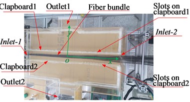
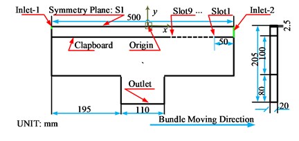
Based on the principle of Venturi, we designed a turbine chamber with some diversion slots. Pneumatic spreader is constructed with acrylic sheets with thickness of 5 mm. The full-scale picture and the geometric diagram are shown in Fig. 1(a). Fibre bundle is fed into the spreader from the left inlet Inlet-1, and output from the right inlet Inlet-2. The origin of the coordinate system is located at the central of the field, and the moving direction of fibre bundle is defined as the -axis. The fibre bundle will be spread in the lateral direction, which is in the positive or negative -axis. The details of the spreader are shown in Fig. 1(b) and Fig. 1(c).
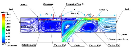
Fig. 1Picture and geometric information of the turbine spreader
a) Full scale picture
b) Half model of the chamber
c) Detail information of the clapboard
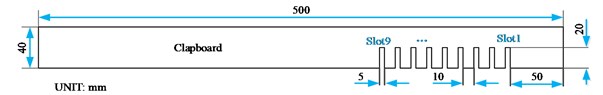
Because the whole structure is symmetric with respect to the plane, a half model of the chamber is built to reduce computational cost. The symmetric plane is denoted as in Fig. 1(b). The left inlet, Inlet-1, is the entrance of un-spread fibre bundle, while the right inlet, Inlet-2, is the exit of fully spread fibre tow. The widths of Inlet-1 and Inlet-2 are 5 mm and 50 mm, respectively. Two clapboards are placed symmetrically with respect to S1, and the distance between the clapboard and the symmetric plane is 25 mm. To generate the lateral dragging force on the bundle in the area near Inlet-2, nine diversion slots, from Slot1 to Slot9, are arranged on the right side of clapboards. Each slot has the width of 5 mm and the height of 20 mm. Outlet is the exit of the airflow in the chamber. The position and arrangement of the diversion slots have huge influence on the shape control of fractal airflow inside the chamber.
2.2. Block division of the CFD model
To ensure the CFD model of the pneumatic chamber is closer to reality, two extension areas, and in Fig. 2, are added into the model, with which the airflow is fully developed as it enters into the analysis domain of the chamber. and are next to the air inlets, Inlet-1 and Inlet-2, respectively. In-1 and In-2 are the left edge of and the right edge of , and they communicate to the outside world. Compared to In-1 and In-2, Inlet-1 and Inlet-2 are the internal inlets of the model. The two entrances of the internal flow field (Inlet-1and Inlet-2) and the nine slots on the clapboard (Slot1~Slot9) are all presented as internal holes in this CFD model, and their mesh types are none. The existence of and can be of huge benefit to the simulation accuracy of the internal flow in the spreader.
Fig. 2Block division diagram of the spreader
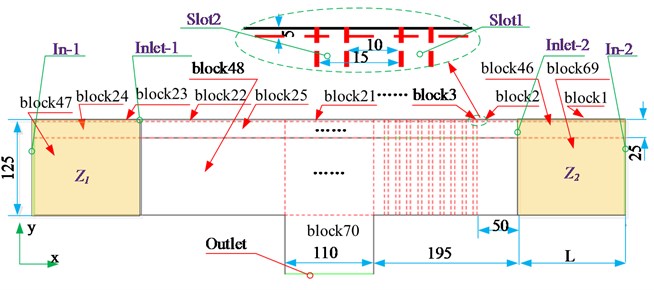
Due to the complex geometric structure of the turbine spreader, multi-block meshing technology is adopted. Along the lateral direction (-axis), the whole solution domain of the CFD model is divided into three layers: the symmetry layer, the diverging layer and the turbine layer. The symmetry layer is the narrow area through the symmetry plane, which is divided into 23 blocks, from block1 to block23. The diverging layer is next to the symmetry layer, which consists of 23 blocks, from block24 to block46. In this layer, the filaments in the bundle are spread and diverged along the lateral direction. Next to the diverging layer is the turbine layer, in which the airflow is obviously turbulent. The turbine layer also consists of 23 blocks, from block47 to block69. From Fig. 2, it can be found that each diversion slot belongs to an independent block. Each separator between two adjacent slots also belongs to an independent block. The area near Outlet belongs to block70. So, the whole solution domain consists of 70 blocks, and flow data can be transferred between blocks. The use of the multi-block meshing method not only improves computational efficiency, but also saves memory.
2.3. Boundary condition of the CFD model
The boundary conditions (BCs) of each object in the model are given in Table 1. Considering the characteristics of internal and external inlets of CFD model, BCs for In-1 and In-2 are set as Pressure-inlet, while BCs for Inlet-1 and Inlet-2 are set as Interior. Both Inlet-1 and Inlet-2 are the inlet of internal flow field, and they allow the air in extension areas going into the chamber. The diversion slots allow the air in the diverging layer flowing through the clapboard into the turbine layer of the chamber, BCs for all slots are set as Interior, too. The symmetric plane of the half model, S1, has the boundary condition of Symmetry type. BC for the edge of the outlet, is Pressure-out type. For the periphery of the chamber, Wall type with fixed and no-slip condition is assigned.
Table 1Boundary conditions and mesh types
Object | Boundary condition type |
In-1 | Pressure-inlet |
In-2 | Pressure-inlet |
Inlet-1 | Interior |
Inlet-2 | Interior |
S1 | Symmetry |
Slots | Interior |
Outlet | Pressure-out |
periphery | Wall |
Taking into account the convection and diffusion terms of turbulence in the turbine layer, a standard - model is used to solve the CFD model. The air velocity inside the spreader is less than 100 m/s, which means the air can be thought as incompressible. According to the recommended values of Launder, the turbulence model parameters are shown in Table 2, where , and are empirical constants; and are the Prandtl numbers corresponding to the turbulent energy and the dissipation rate .
Table 2Model constants employed in the fluent model
1.44 | 1.9 | 0.09 | 1.9 | 1.0 | 1.2 |
3. Experiments and simulation
3.1. Verification of CFD model with experimental data
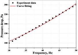
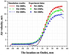
During the experiments, the electronic micro-manometer MP115 is used to measure the pressure drop between the center of Inlet-2 and the center of Outlet. The pressure drop is controlled by the centrifugal fan, which is linked to the outlets (Outlet) of the chamber by air pipelines. A frequency converter is used to control the centrifugal fan, and the linear relationship between the frequency and pressure drops is shown in Fig. 3(a). This linear relationship is determined by the power of the centrifugal fan. To verify the CFD model, the air velocities on the output port, Outlet, have been measured and compared with simulation results shown in Fig. 3(b). It can be found that velocities on the left half of Outlet is relatively smaller than the right half, and there are dramatically speeding up at the point –5 mm for different pressure conditions. Experimental data agree well with simulation results, which verifies the validation of the CFD model. In the CFD model, the boundary conditions for both inlet ports, In-1 and In-2, are set to standard atmospheric pressure (101325 Pa). The lengths of the extensions, and , are all set to 150 mm.
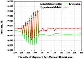
The pressure distribution along fibre moving direction, were measured and compared with the simulation results, as shown in Fig. 3(c). The airflow occurs dramatical oscillations in the -axis, and there are nine peaks of different magnitudes, which corresponds to dragging forces of the airflow near the nine slots on the clapboard. It can be seen that the magnitude of pressure along the -axis is gradually decreasing, which means the dragging force of the airflow near the –100 mm is obvious greater than the areas near Inlet-2, the output port of spread fibre bundle. This phenomenon of airflow greatly benefits to the efficiency and stability of the spreading behavior. The hug dragging force in -axis direction and airflow oscillations near Slot7-Slot9 can overcome the binding among fibrilla within the bundle, and break the bundle well. The generally decreasing dragging force near Inlet-2 will ensure the fluctuation of fibrilla in -axis, which has great influence on the uniformity of tow thickness.
Fig. 3Verification of CFD model with experimental data
a) Frequency vs. pressure
b) Air velocity on outlet
c) Pressure drops in slots zone
3.2. Characteristics of streamlines in turbine spreader
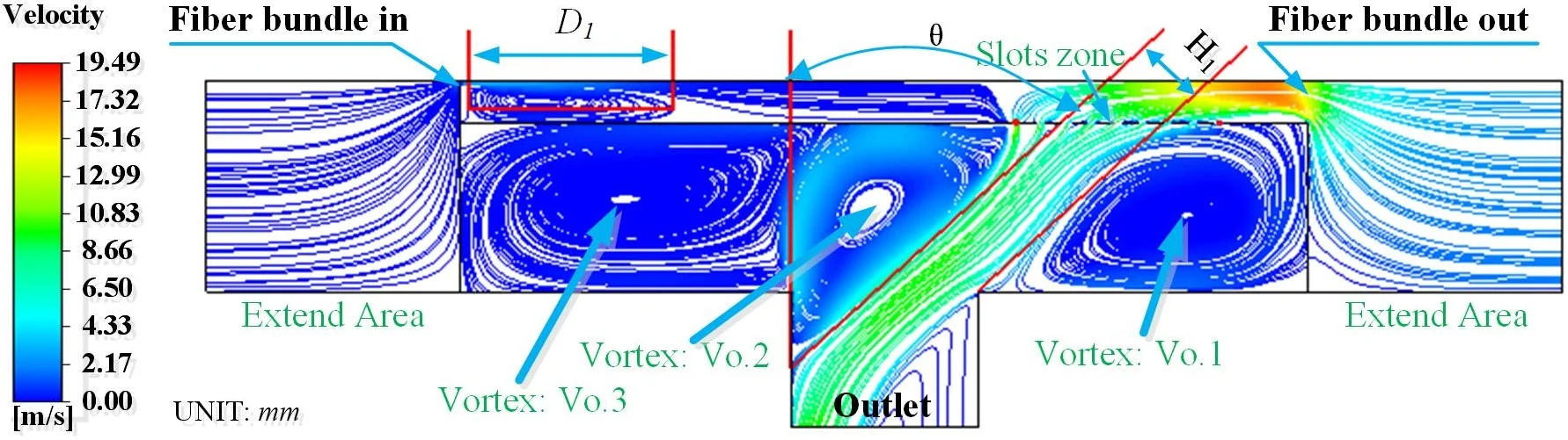
The streamlines distribution in the spreader is shown as Fig. 4(a), from which it can be found there are three vortices, denoted by Vo.1, Vo.2 and Vo.3 in the turbine layer, one stagnation area and one high-speed area. The characteristics can also be found in Fig. 4(b), which is the simulation results with discrete element method (DEM). DEM plot is based on the Euler multiphase flow, in which the main phase is air, and the secondary phase (the discrete phase) is anthracite particles. The diameter of particles is 0.01 mm and its viscosity is 1e-05 (kg/m-s). With this method, the characteristics of flow field in the spreader are represented in the form of particles dispersion.
Fig. 4Characteristics of the flow field of the spreader
a) Streamline distribution
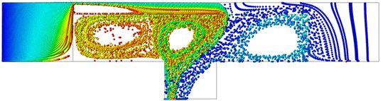
b) Represented in the form of particles dispersion
By comparing Fig. 4(a) and Fig. 4(b), it can be found the air in the extension areas, and , are absorbed into the chamber from the left inlet (Inlet-1) and the right inlet (Inlet-2). Air velocity near Inlet-2 is much larger than that near Inlet-1. This is due to the existence of diversion slots on the right side of the clapboard. The flow blown from Inlet-2 goes through the diversion slots, and forms a linear flow zone, whose width and direction are donated by the parameters and , respectively. The flow is blown to the left side of Outlet, and it makes the greatest contribution to the dragging force applied on the fibre bundle. To parametrically analyze the fractal airflows, some variables are given to describe the size and position of the characteristic elements of the model. The length of the stagnation area is labeled by variable . The width and orientation of the high-speed area are represented by variables and , respectively. The airflows through the 9 slots are characterized by 9 speed variables, ~.
3.3. Influence of pressure drops on fractal airflow
In order to improve the uniformity of fibre spreading, it is necessary to set a reasonable pressure drop between the inlets and outlet of the pneumatic spreader. Three different pressure drops conditions have been experimented and simulated: 200 Pa, 250 Pa and 300 Pa. The influence of pressure drop on fractal airflow can be found from Table 3. With the increasing of pressure drop, and increase continuously. Under the same length of the extended area, variables, , , and , have no obvious changes.
Table 3Parametric characteristics of flow fields under different pressure drops
Pressure drop Pd | 200 Pa | 250 Pa | 300 Pa |
Speed at Slot1 / (m/s) | 3.61 | 3.99 | 4.33 |
Speed at Slot9 / (m/s) | 10.38 | 11.4 | 12.7 |
Linear flow area width / mm | 31.2 | 33.3 | 33.9 |
The angle / | 46 | 48 | 46 |
Sluggish area length / mm | 120.9 | 120.5 | 119.8 |
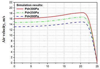
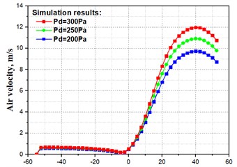
Influences of pressure drop on the air velocity near the inlet (Inlet-2) and the outlet (Outlet) of the solution domain are shown in Fig. 5(a) and Fig. 5(b), respectively.
Fig. 5Influence of pressure drops on velocities on Inlet-2 and Outlet
a) Air velocity on Inlet-2
b) Air velocity on Outlet
Both air on Inlet-2 and Outlet, speed up gradually with the increasing of pressure drop. The horizontal axis in Fig. 5(a) is the distance from the symmetric plane () to a point on Inlet-2, and the distance from to the clapboard is 25 mm. The air flow near is stable in the symmetric layer, and the velocity is slightly increased in the diverging layer. As the air gets closer to the clapboard, its velocities rapidly decrease to zero. The horizontal axis in Fig. 5(b) is the position of a point on Outlet. The air velocity on the left side (negative half) of Outlet is relatively smaller. When it approaches the center of Outlet, the air velocity is close to zero. The air velocity on the right side (positive half) of Outlet increases dramatically, and reaches its peak at the location 40 mm. Then each velocity curve has a decreasing trend.
3.4. Influence of diversion slots on fractal airflow
The position of the 9 slots on the clapboard is identified by two variables and , where represents the distance from the rightmost slot to the right edge of the board, and Hs is used to label the distance between the two adjacent slots. As shown in Table 4, six different cases with different values of and have been analyzed, and their influence on fractal airflow are compared. For these six cases, the air velocities in the lateral direction (-axis) are shown in Fig. 6. Each diversion slot corresponds to a peak of the velocity curve, and the negative value of flow velocity means the airflow is blown in the opposite direction of the -axis. By comparing these six cases, it has been found the airflow in Case 2-1 is the best one in term of the stable velocity and low shock between adjacent slots. The airflow in Case 2-1 can spread fibre bundle evenly, and the performance will be more uniform.
Table 4Flow field numbering and fractal flow path parameters
Case ID | (mm) | (mm) |
1-1 | 50 | 15 |
1-2 | 50 | 25 |
2-1 | 25 | 15 |
2-2 | 25 | 25 |
3-1 | 5 | 15 |
3-2 | 5 | 25 |
Fig. 6Influence of diversion slots position on flow velocity
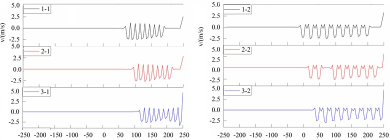
Fig. 7Influence of diversion slots position on fractal airflow
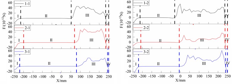
The dragging force of flow field in the lateral direction (-axis) is shown in Fig. 7. The flow field in each case is divided into four sub-fields, from I to IV, along the moving direction of fibre bundle. Sub-fields I and IV are the entrance part and the exit part of airflow, respectively. Sub-fields II and III are the smoothly conveying part and gradually spreading part. The spreading performance of the turbine chamber is mainly influenced by the airflow in the sub-field III. The diversion of airflow is constrained in the sub-field IV, which ensure the stable output of the fibre bundle. From the six-plots in Fig. 7, it also can be found that the dragging force in the case 2-1is stabler than the others.
Pictures of fibre bundles captured during the spreading process are shown in Fig. 8. Pictures in Fig. 8(a) and Fig. 8(b) were captured by the CMOS cameras near Inlet-1 and Inlet-2, respectively. There are 12,000 carbon fibre filaments in the bundle. The width and thickness of un-spread fibre bundle are about 5.0 mm and 0.48mm, while the width and thickness of fully spread fibre tow are about 50.0 mm and 0.04 mm. The width of the bundle has been widened almost 10 times, which has improved by 100 % compared with traditional mechanical spread method.
Fig. 8Pictures of fibre bundles captured during the spreading process
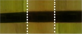
a) Un-spread bundle captured near Inlet-1
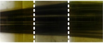
b) Spread tow captured near Inlet-2
4. Conclusions
Pneumatic spreading technology has the advantages of less pollution to the environment and less friction to the surface of fibres. Based on the experimental and computational analysis of the flow field in the spreader, a pneumatic spreader is designed, and some conclusion has been drawn:
1) By graphically analyzing of the fractal airflow, the streamlines distribution in the spreader are parametrically modelled, which greatly benefits to the optimization and the mechanism analysis of the turbine spreading chamber. In the CFD model of the spreader, there includes three vortices, one stagnation area and one high-speed area.
2) With the help of Euler multiphase flow, the characteristics of flow field in the spreader are represented in the form of particles dispersion, with which the generation and evolution process of lateral spreading of large-size fibre bundle is illustrated graphically, and a better understanding of the laterally spreading of the large-size fibre bundle can be obtained.
3) By analyzing the influence of pressure drop on fractal airflow, the relevant design parameters are optimized to obtain the target of evenly spreading of bundle. With the increasing of pressure drop, air velocity near slots increases continuously, while other variables of the fractal airflow, such as DL, , and , was not significantly affected by pressure drop.
4) With the multi-block technology, the influence of diversion slots on fractal airflow was investigated and the positions of these slots are optimized. The existence of the clapboard with 9 slots makes favor to the lateral spreading of fibre bundles: the airflow occurs dramatical oscillations in the -axis near slots generate enough dragging forces, which greatly benefit to the efficiency and stability of the spreading behavior.
References
-
Y. Chiker, M. Bachene, S. Bouaziz, M. Guemana, M. B. Amar, and M. Haddar, “Free vibration analysis of hybrid laminated plates containing multilayer functionally graded carbon nanotube-reinforced composite plies using a layer-wise formulation,” Archive of Applied Mechanics, Vol. 91, No. 1, pp. 463–485, Jan. 2021, https://doi.org/10.1007/s00419-020-01783-3
-
T. Laux et al., “Modelling damage in multidirectional laminates subjected to multi-axial loading: ply thickness effects and model assessment,” Composite Structures, Vol. 266, p. 113766, Jun. 2021, https://doi.org/10.1016/j.compstruct.2021.113766
-
A. Arteiro, G. Catalanotti, J. Xavier, P. Linde, and P. P. Camanho, “Effect of tow thickness on the structural response of aerospace-grade spread-tow fabrics,” Composite Structures, Vol. 179, pp. 208–223, Nov. 2017, https://doi.org/10.1016/j.compstruct.2017.06.047
-
H. M. Mallikarachchi, “Predicting mechanical properties of thin woven carbon fibre reinforced laminates,” Thin-Walled Structures, pp. 297–305, 2018, https://doi.org/10.1016/j.tws. 2018.11.016
-
S.-M. Park, M.-S. Kim, Y. S. Choi, E.-S. Lee, and J.-S. Chon, “Carbon fiber tow spreading technology and mechanical properties of laminate composites,” Composites Research, Vol. 28, No. 5, pp. 249–253, Oct. 2015, https://doi.org/10.7234/composres.2015.28.5.249
-
T. A. Sebaey and E. Mahdi, “Using thin-plies to improve the damage resistance and tolerance of aeronautical CFRP composites,” Composites Part A: Applied Science and Manufacturing, Vol. 86, pp. 31–38, Jul. 2016, https://doi.org/10.1016/j.compositesa.2016.03.027
-
S. L. J. Millen, A. Murphy, G. Catalanotti, and G. Abdelal, “Coupled thermal-mechanical progressive damage model with strain and heating rate effects for lightning strike damage assessment,” Applied Composite Materials, Vol. 26, No. 5-6, pp. 1437–1459, Dec. 2019, https://doi.org/10.1007/s10443-019-09789-z
-
R. M. Baucom and J. M. Marchello, “LaRC powder prepreg system,” SAMPE Quarterly (Society of Aerospace Material and Process Engineers), Vol. 21, No. 4, 1990.
-
Sihn S., Kim R., Kawabe K., and Tsai S., “Experimental studies of thin-ply laminated composites,” Composites Science and Technology, Vol. 67, No. 6, pp. 996–1008, 2007, https://doi.org/10.1016/j. compscitech.2006.06.008
-
F. Ren, Y. Yu, M. Cao, Y. Li, C. Xin, and Y. He, “Effect of pneumatic spreading on impregnation and fiber fracture of continuous fiber-reinforced thermoplastic composites,” Journal of Reinforced Plastics and Composites, Vol. 36, No. 21, pp. 1554–1563, Nov. 2017, https://doi.org/10.1177/0731684417718085
-
H. M. El-Dessouky and C. A. Lawrence, “Ultra-lightweight carbon fibre/thermoplastic composite material using spread tow technology,” Composites Part B: Engineering, Vol. 50, pp. 91–97, Jul. 2013, https://doi.org/10.1016/j.compositesb.2013.01.026
-
Huang B., Yuan S., and Xue J., “Spreading process simulation and experimental investigation for a carbon fibre pneumatic spreader,” Journal of Xian Jiaotong University, 2015, https://doi.org/10.7652/xjtuxb201512004
-
J. A. Newell and A. A. Puzianowski, “Development of a Pneumatic Spreading System for Kevlar-Based Sic-Precursor Carbon Fibre Tows,” High Performance Polymers, Vol. 11, No. 2, pp. 197–203, Jun. 1999, https://doi.org/10.1088/0954-0083/11/2/004
-
J. W. Klett and D. D. Edie, “Flexible Towpreg for the fabrication of high thermal conductivity carbon/carbon composites,” Carbon, Vol. 33, No. 10, pp. 1485–1503, 1995, https://doi.org/10.1016/0008-6223(95)00103-k
About this article

This work was supported by the Natural Science Foundation of Tianjin (Grant No. 18JCYBJC89000) and the National Natural Science Foundation of China (Grant No. 52175110).
The datasets generated during and/or analyzed during the current study are available from the corresponding author on reasonable request.
The authors declare that they have no conflict of interest.
