Abstract
A few volume of lubricate oil leaking inside the cavity of the rotating drum can cause severe vibrations, which have been observed on-site at aero-engine compressors. This paper proposes a modeling method for the rotor system which is excited by the oil-block. Firstly, the differential equations of the lumped dynamic system of a representative rotor system with a congregated oil-block inside the drum are deduced, in which the external excitation force caused by oil-block is modeled equivalently by both inertial force and sliding frictional force. Then, numerical simulations are carried out to demonstrate the transverse vibration behaviors of the rotor system and both rotating speeds and mass of the oil-block are taken into account. The obtained nonsynchronous whirling vibrations of the rotor system caused by the oil-block are validated by experimental measurements of transverse vibrations of the shaft on a rotor test rig. The results show that, when the rotating speed runs up to the first critical speed, the oil-block will slide along the inner wall of the drum and keep on rotating with the drum delayed in a slowly changing phase angle, and the amplitudes and frequency spectra of the nonsynchronous whirling vibrations of the shaft are found to be sensitive to the oil mass and viscous damping coefficients of the system.
1. Introduction
The rotor systems of aero-engine compressors which shafts are made of multi-stage cylindrical drums easily encounter severe vibrations due to a few of lubrication oils leaked into the drum cavity, where the oil leakage reason is often due to improper structure assembly or malfunction seals. It was also observed on-site that, even the mass of the oil-block leaked inside the drum cavity is a very little, the excited vibrations of the machine are very severe and known to be nonsynchronous whirling vibrations of its rotor system [1, 2]. The oil-block caused vibrations of rotor system are different from those caused by unbalance, which are known to be synchronous and the related knowledge is popular [3-6].
The effect of the oil leaked inside the rotating drum cavity on the rotor system can be considered as a type of fluid-structure interaction. The first claim reported by Wynne [1] was that the frequency component of the excited vibration due to oil inside rotor is about 0.9 of the critical speed of the rotor system. The related work has been reported on rotors partly filled with liquid to a certain extent. Colding-Jfirgensen [7] compared the instability scopes of a rotating cylinder with partially filled liquid by experimental results and theoretical analyses, and emphasized the nonlinearity effect of external damping viscosity of fluid. Cventicanin [8] studied the influences of fluid forces and external forces on the self-exciting vibrations of the rotor system with variable mass. Derendyaev et al. [9] demonstrated the behaviors of the rotor system partly filled with liquid were obtained qualitatively and quantitatively with continuous and discrete models, and indicated that Andronof-Hopf bifurcation of steady-state motion might occur.
In order to explore the observed serious vibration phenomena of the air compressor of aero-engines and gas turbine generators on-site, which is due to oil leaked inside the cavity of the rotating drum, some experimental researches by using of a simple rotor test rig were conducted by the authors [2, 10, 11]. It is found that the oil inside the rotating drum will rotate along the drum wall but obviously delays below the synchronous rotating speed when the rotating speed runs up and exceeds the first critical speed. In the authors past work [2], the kinematics of the oil-block is described and the exciting force of the oil-block applying on the drum is also hypothetically expressed in the way of contacting friction. The oil-block motivation is derived based on the theorem of acceleration composition with the help of both its Coriolis acceleration and transferable rotational acceleration.
In this paper, a new dynamic model is set up based on a prototype of a simple but representative rotor test rig with a rotating drum containing some oil inside its cavity. Different from [2] and referencing its simulation results, this paper does not take the gyroscopic effect into consideration during the modeling. The effectiveness of the oil-block inside the drum cavity is equivalently simplified to be as the external excitation by a lumped mass with sliding friction. Numerical simulations are carried out based on the proposed model for the shaft vibrations and the movements of the oil-block. At last, the simulated nonsynchronous vibrations of the rotor system show similar behaviors of the experimental measurements on the test rig.
2. Modeling of the rotor system with oil-block inside its drum cavity
A simple rotor test rig is designed to study the vibrations of the rotor system excited by oil leakage, shown in Figure 1, is driven by an electrical motor. The rotating speed of the rotor can be tuned by the driving voltage. The rotor consists of a long shaft, and two ball bearing supports. A steel disk and a hollow cylinder drum (which is at the right side) are installed on the shaft symmetrically. The oil drum is made of nylon, which is transparent so as to observe the oil movements inside its cavity.
Fig. 1The rotor test rig with oil-block inside the drum
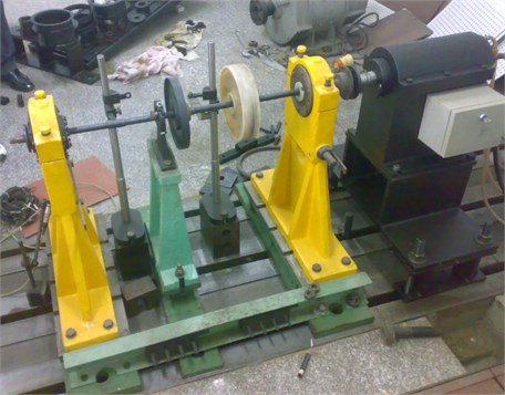
Fig. 2Schematic of the rotor system

The schematic of the rotor rig is shown in Figure 2. The dynamic model of the rotor system is set up based on the lumped mass assumption. The model parameters are listed in Table 1. The first two critical speeds of the rotor system are calculated as 32.9 Hz and 104.6 Hz, respectively, and the first mode of it is a pitch pattern combining bending and the second mode is the shaft bending one [8]. The shaft will run below the speed of 80 % of the second critical speed, which is much higher than the first critical speed.
Table 1Parameters of rotor system in simulations
Parameters | Values |
Shaft diameter | 12 mm |
Shaft length | 487 mm |
Distance of steel disk or drum to its nearby bearing center | 139.5 mm |
Diameter of the steel disk, the left one | 200 mm |
Diameter of the oil disk, the right one | 210 mm |
Width of the oil disk | 20 mm |
Density of steel disk and shaft | 7800 kg/m3 |
Young modulus of steel disk and shaft | 2.05×10¹¹ Pa |
Mass of steel disk | 0.9606 kg |
Mass of oil disk | 2.0376 kg |
Density of oil disk | 1400 kg/m3 |
Supporting stiffness of the left end | 1×10¹⁰ N/m |
Supporting stiffness at the right end | 3.8693×10⁴ N/m |
Stiffness of the three shaft segments | 1.0081×10⁵ N/m |
5.1105×10⁵ N/m | |
1.0081×10⁵ N/m | |
The first order critical speed of rotor system | 32.919 Hz |
The second order critical speed of rotor system | 104.61 Hz |
Eccentric radius of steel disk | 95 mm |
Eccentric mass of steel disk | 1.0 g |
Eccentric radius of oil disk | 95 mm |
2.1. The differential equations of the rotor system
The transverse vibration displacements of the steel disk and the drum are noted as , in vertical and horizontal directions, as shown in Figure 2. Assume that the steel disk and the drum have small unbalance masses respectively, and the drum is also excited by the force induced by the oil-block inside. The equivalent lumped masses of them are . The eccentric radii of the two disks are , respectively. The shaft segments are simplified as massless elastic beams. In the case of no phase difference between two eccentric masses of the two disks of and the rotating angular speed of , the differential equations of motions of the rotor system are as follows:
where, , are the horizontal and vertical force components applying on the oil drum induced by the oil-block. are the viscous damping coefficients of the system. , are the stiffness of the three shaft sections. is the summation of shaft section and left supporting stiffness i.e. So is . . The values of are listed in Table 1.
2.2. Forces of the oil-block inside drum
The oil-block fault is a typical problem of fluid and structure coupling. In this paper, the oil-block is assumed as a dot mass, and only its rigid motion together with friction effect is considered. In this way, the oil-block effectiveness can be modeled in the forms of normal force and tangential force.
The schematic of the oil induced forces on the drum is shown in Figure 3, where Point C is the geometric center of the drum and Point O is the rotation center. It is assumed that the geometric shape of the oil-block will not change when running since it is formed, and do not rotate about its mass center nor scroll.
Fig. 3Diagram of the force induced by the oil-block
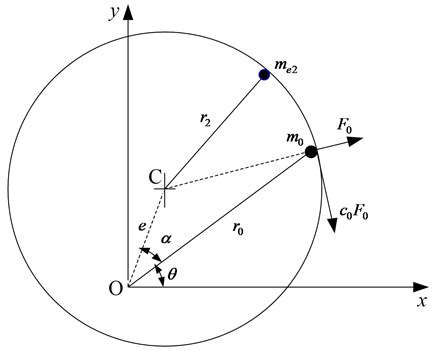
According to experimental observation, the whirling speed of the oil-block will be behind the rotating speed of the rotor, so that the rotating angle of the oil-block is assumed to be:
where is the rotating angle that oil-block delays behind the reference point fixed on the drum.
The decomposed components of the force of the oil-block acting on the drum, i.e. the normal force and the friction force caused by the oil-block, are:
where, is the friction coefficient between the oil-block and the inner wall of the drum, and is the distance between the oil-block and the rotation center O. As shown as Figure 3, is expressed as:
where .
So the external forces in horizontal and vertical directions in Eq. (1) due to the oil-block are as follows:
For the oil-block, also referring Figure 3, to consider its tangential velocity as:
and then its dynamic equation can be driven as follows:
2.3. Compared with unbalanced rotor system
To compare the effort of the oil-block on the non-synchronization or frequency locking of rotor vibrations shown below, the oil-block is treated as an unbalance in the numerical simulations of the rotor system. In this case, the oil-block mass is set as the unbalance mass on the oil disk, with the unbalance radius of . The unbalance on the steel disk is in the same phase of the dummy unbalance of oil-block on the oil drum. Equation (1) is then revised as follows:
Comparing Eqs. (1), (5) with (8), there are significant differences between the governing equations of the rotor system with either oil-block or unbalance mass. Firstly, the unbalance of the rotor system caused by eccentric mass is the well-known synchronous whirling; nevertheless, the oil-block will lead to a non-synchronous motion of the rotor system as discussed below.
3. Simulation results
3.1. Simplification of the governing equations of the rotor system
Suppose that the rotating speed of the shaft is constant and the rotary angular acceleration is zero during the following simulations. In order to conveniently study the effects of the movements of the oil-block, the equations of and have to be linearized. Because the vibration magnitudes of the shaft are much smaller than the radius of oil drum, Eq. (4) can take the zero order approximation as follows:
The approximation of in Eq. (9) is acceptable. Considering
, and , we can assume that . In addition, can also be expressed by and , those are the vibration displacement components of the drum, i.e. . It is certainly is much smaller than .
According to Eq. (2), i.e. , we can obtain the velocity equation of it as . Substituting it to Eq. (3), we have:
It is also can be assumed that the changing of the oil-block lag angle, , is much smaller than the rotating speed of the shaft, . If taking , is a small parameter, then it is obtained as follows:
The simulations are carrying out by directly numerical integration of Eq. (1), (2), (5) and (7), combing the approximated treatments of Eq. (9-11), based on Runge-Kutta method. These equations are listed together as follows:
3.2. Shaft vibrations with different oil-block masses
Effects of the oil-block mass upon the vibrations of rotor system are discussed firstly. The parameter values of the oil-block used in simulations are listed in Table 2.
Table 2Parameter values of the oil-block used in simulations
Case 1 | Case 2 | Case 3 | Case 4 | |
Mass of the oil-block | 0 (without oil) | 1.85 g | 3.7 g | 5.55 g |
Volume of the oil-block | 0 | 2 ml | 4 ml | 6 ml |
Damping coefficient of oil-block | 0 | 1 N/(m/s) | 1 N/(m/s) | 1 N/(m/s) |
In simulations, the rotating speed of the rotor will go smoothly and slowly from a low one up to a higher point, i.e. from 20 Hz to 62 Hz, and then run down from 62 Hz to 20 Hz steadily. The 3D diagrams of frequency spectra of vibrations of the drum in direction are illustrated in Figure 4.
Figure 4 shows that the developing processes of the vibrations of the oil drum. For the case of only existing eccentric mass without oil-block, as Figure 4(a), the 3D frequency spectra of the drum vibration are smooth and stable in the non-resonant frequency ranges. There are two obvious resonances, and the resonance frequencies are same to the first critical speed of the rotor system.
Three cases of 2 ml, 4 ml and 6 ml oils in the drum are shown in Figure 4(b), (d) and (f), respectively. These frequency spectra demonstrate that the oil-block rotates along the inner wall of the drum in a delay phase when the rotating speed runs over the first critical speed. The sub-harmonics caused by the oil-block will keep consistently, until the rotor runs down to the first critical speed again. It is regarded as the frequency-locking phenomenon. It can also be seen that the nonsynchronous vibration are slightly different among Figure 4(b), (d) and (f).
In the contrasting simulations based on Eq. (8) where the oil-block is treated only as an unbalance, the frequency spectra of vibrations of the drum are shown in Figure 4(c), (e) and (g). Similar to Figure 4(a), the 3D frequency spectra of the drum are also smooth and stable in non-resonant frequency ranges. The two amplitudes of obvious resonances, which correspond to the first critical speed, increase with the volume or mass of the dummy oil-block. Comparing with Figure 4(b), (d) and (f), because the oil-block has been simplified to an unbalance, the oil-block rotates with the drum in a synchronous way and the frequency-locking phenomenon does not appear.
Fig. 43D frequency spectra of the oil disk in x direction
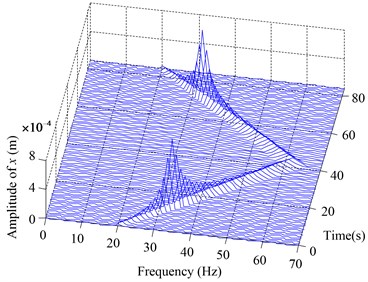
a) without oil-block
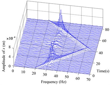
b) with a 2 ml oil-block
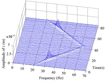
c) with a 2 ml oil-block regarded as an unbalance
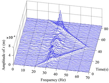
d) with a 4 ml oil-block
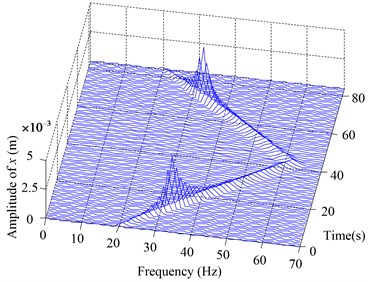
e) with a 4 ml oil-block regarded as an unbalance
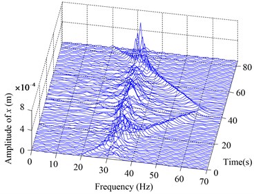
f) with a 6 ml oil-block
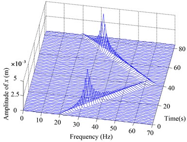
g) with a 6 ml oil-block regarded as an unbalance
3.3. Vibrations with different rotate speeds
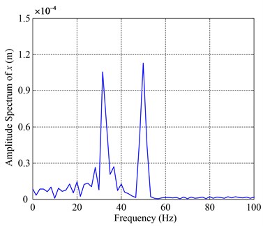
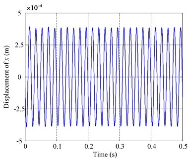
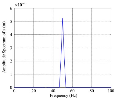
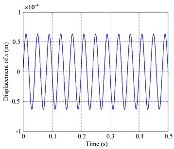
In order to compare the influence of the rotating speeds on vibrations of the rotor system with oil-block, two simulations at different speeds of 50 Hz and 25 Hz are illustrated in Figure 5 and Figure 6. The first rotating speed of 50 Hz is higher than the first critical speed of the rotor system and the second is below it. The oil-block is set to be the same mass of 3.7 g (4 ml).
Fig. 5Vibrations of the oil disk in x direction at rotating speed 50 Hz
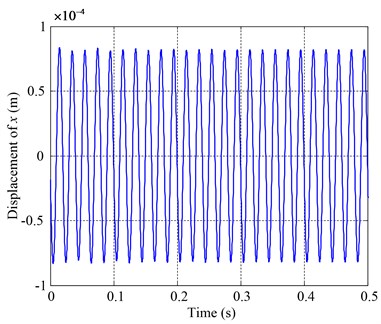
a) Time history without oil-block
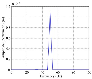
b) Amplitude spectrum without oil-block
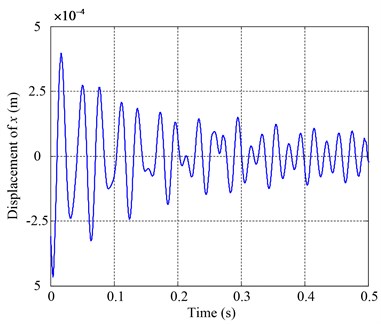
c) Time history with a 4 ml oil-block
d) Amplitude spectrum with a 4 ml oil-block
e) Time history when a 4 ml oil-block regarded as an unbalance
f) Amplitude spectrum when a 4 ml oil-block regarded as an unbalance
Fig. 6Vibrations of the oil disk in x direction at rotating speed 25 Hz
a) Time history without oil-block
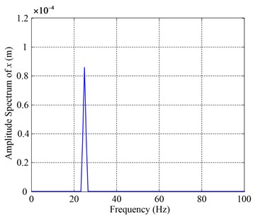
b) Amplitude spectrum without oil-block
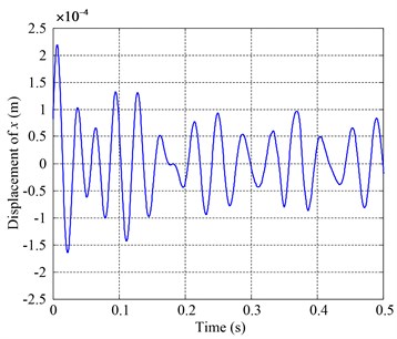
c) Time history with a 4ml oil-block
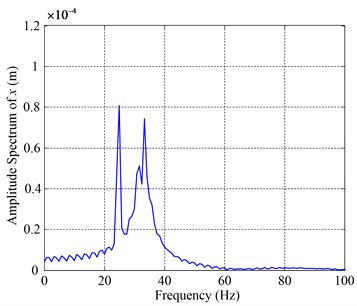
d) Amplitude spectrum with a 4ml oil-block
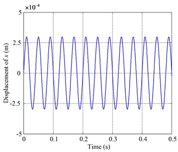
e) Time history when a 4 ml oil-block regarded as an unbalance
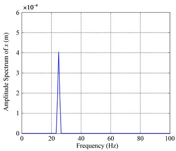
f) Amplitude spectrum when a 4 ml oil-block regarded as an unbalance
Figure 5(a) and (b) are the simulated vibration responses of the drum without oil-block in time domain and frequency domain at the rotating frequency of 50 Hz which are single frequency harmonic and caused by the eccentric mass on the steel disk. Figure 5(c) and (d) are the vibration responses of the drum with 4 ml oil-block in time domain and frequency domain at the rotating frequency of 50 Hz. It can be seen that there are sub-harmonics in the spectrum diagrams, including 31.7 Hz and 36.7 Hz. When the 4ml oil-block is regarded as an unbalance, as shown in Figure 5(e) and (f), the vibration response of the drum is a single harmonic, which corresponds to the rotating frequency, and the amplitude is much larger than that of Figure 5(b) or (d).
Keeping the oil-block mass unchanged and the rotating frequency becomes 25 Hz, which is lower than the first critical speed of the rotor system. Figure 6(a) and (b) are the responses of the drum without oil-block at the rotating frequency of 25 Hz. Figure 6(e) and (f) are the responses of the drum when the oil-block is regarded as an unbalance. They are all the single harmonic vibration. The higher harmonics appear due to the excitation of oil-block, as shown in Figure 6(c) and (d). In this case of lower rotating speed, the higher frequency bands are greatly nearby the first critical frequency of the rotor system.
4. Experimental results of the rotor test rig
The measured vibrations of the corresponding test rig shown in Figure 1 are described here. In the experiments, the lubricant oil of No. 32# is added into the drum. The volumes of the two kind oils are 2 ml, 4 ml respectively. The vibrations at two shaft ends are measured for vertical and horizontal directions with eddy-current displacement sensors. The frequency spectra of the shaft displacements in vertical direction measured near the supporting end are illustrated in Figure 7 for these different cases.
Fig. 7Experimental frequency spectra of rotor rig
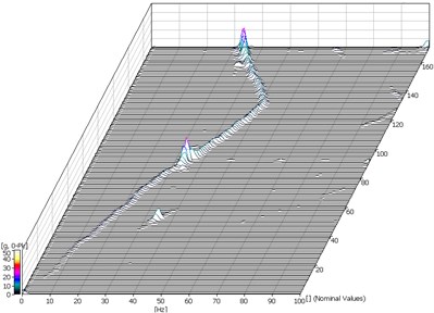
a) Spectra without oil
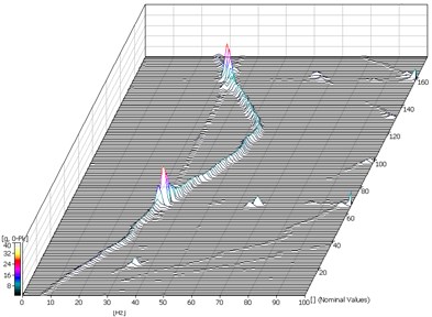
b) Spectra with 2ml oil 32#
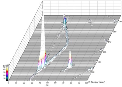
c) Spectra with 4ml oil 32#
From the experimental results, even with a few volumes of oils added into the rotating drum, the rotor system will suffer severe self-excited vibrations, and which frequency bands are often quite wide and sensitive to the mass of the oil-block.
As shown in Figure 7(a), comparing to Figure 7(b) and (c), with the same oil drum, the self-excited vibrations of the rotor will be greater with increasing of the oil mass. The frequency bands of the excited vibrations due to oil-block will also become wider. It can be seen that the frequency components are about from 0.6 to 1.0 times of the rotor rotating frequency from the frequency spectrum diagrams.
It is also found from test rig experiments that, once a few of oil inside existing, the rotor will be difficult to run up and pass through its critical speed. The amplitude and frequency ranges of the self-excited vibration caused by oil are correspondingly to the mass of oil-block just as all the frequency spectra shown in Figure 7.
5. Conclusions
In this paper, a lumped dynamic model of the rotor system with an oil-block inside the rotating drum is set up, referring to the given prototype of a simple but representative rotor test rig.
The proposed model in this paper is established based on interaction of oil-block (namely normal force and tangential friction force) on the rotor system, which is necessary to predict essential characteristics of the rotor system with oil-block inside its drum cavity.
The numerical simulations based on the proposed dynamical model are carried out to reveal the different vibration behaviors of the rotor system with oil-block due to both oil masses and rotating speeds. The simulations demonstrate that, when the rotating speed runs up to the first critical speed, the oil-block will slide along the inside wall of the drum and keeps on rotating with the rotor asynchronously, which induces obvious non-synchronous whirling vibrations. The results also indicate that the oil-block can be not simply regarded as an unbalance.
The measured results from rotor test rig show that the amplitudes and frequency bands of the shaft vibrations are affected by the oil mass and the viscous coefficients sensitively and positively. The obtained experimental measurements are shown the same vibration behaviors with the numerical simulation results based on the proposed model of the rotor system.
References
-
Wynne J. B. Advances in aero engine dynamics. 22nd Joint Propulsion Conference, Huntsville, Alabama, 1986.
-
Han Q., Wang M., Chu H. Nonsynchronous vibrations of rotor system with an oil-block inside the rotating drum. Advances in Vibration Engineering, Vol. 12, Issue 2, 2013, p. 165-178.
-
Genta G. Dynamics of Rotating Systems. Spring, Dordrecht, 2005.
-
Zhang G., Wei J., Huang H., Zhou M. A study on the nonlinear vibration of the generator rotor based on the unbalanced electromagnetic force and the oil film force coupling model. Journal of Vibroengineering, Vol. 15, Issue 1, 2013, p. 23-36.
-
Muszynska A. Rotordynamics. Taylor & Francis, Boca Raton, 2005.
-
Sarsekeyeva A., Ragulskis K., Navickas Z. Dynamic synchronization of the unbalanced rotors for the excitation of longitudinal traveling waves. Journal of Vibroengineering, Vol. 10, Issue 1, 2008, p. 1-10.
-
Colding-Jorgensen J. Rotor whirl measurements on a long rotating cylinder partially filled with liquid. Journal of Vibration and Acoustics, Vol. 115, 1993, p. 141-143.
-
Cventicanin L. Self-excited vibrations of the variable mass rotor/fluid system. Journal of sound and vibration, Vol. 212, 1998, p. 685-702.
-
Derendyaev N. V., Vostrukhov A. V., Soldatov I. N. Stability and andronov-hopf bifurcation of steady-state motion of rotor system partly filled with liquid: continuous and discrete models. Journal of Applied Mechanics, Vol. 73, 2006, p. 580-589.
-
Chen X. Simulations for rotor system with oil-leakage. Master Thesis of Northeastern University, 2008.
-
Han Q., Jin S., Wen B. Dynamical simulations of a rotor system with oil-leakage fault. Indian Institute of Technology, Delhi, 2009.
About this article
This work was financially supported by National Natural Science Foundation of China (Grant No. 51175070), and National Basic Research Program of China (973 Program, Grant No. 2012CB026005).
