Abstract
With robots used widely in many fields in recent years, the underwater robot with various characteristics has been thoroughly researched. As a new type of underwater spherical robot, BYSQ-2 uses the heavy pendulum to adjust the attitude, which is flexible and novel. However, it has been not fully understood that how the heavy pendulum would affect the underactuated robot’s regular movement. In this paper a fluctuation characteristic for the robot is shown, and then an adaptive control method is proposed to suppress the fluctuation. Based on the simplified structure of the robot, a swing phenomenon of the heavy pendulum is found. Moreover, the reason for the fluctuation is analyzed in the processes of the accelerating and pitching. A dynamic equation for this model is established to accurately calculate the characteristic, and the virtual simulation proves the validity of the theoretical calculation. The characteristics of this coupling fluctuation are summarized by changing motion parameters and structure parameters. The results prove that the pendulum’s length and the controlling process are closely related with the velocity fluctuation of the robot. Moreover, in order to suppress the fluctuations, a pitching controller is designed to prevent the heavy pendulum from swinging based on the method of neural network sliding mode. The RBF neural network is used to compensate the nonlinearity and disturbance uncertainties, and two sliding mode structures make the swing rapidly inhibited. At the same time, the pitch angle's error also got convergence. The stability of the control system is proof by Lyapunov and Barbalat theories. Finally, the simulation and experiment show that the control method is feasible and excellent, which can fulfill the suppressed control for the fluctuation of the robot.
1. Introduction
Mini Underwater Robot (Autonomous Underwater Vehicle) has been widely used in the fields of civil, industrial and scientific research. In recent years, AUV also gets attention in military field and attracts more and more researchers. On the one hand it is easy carry, flexible movement and low cost, which is convenient for scientific exploration and data acquisition, on the other hand it has the advantages of low noise and good concealment, which can be used to implement underwater investigation, sea assault and other military tasks. US Marine Corps (2004) developed 9 missions, and fully affirmed the importance of the AUV, but the low-speed stability of the underwater robot is one of the key technologies that need to be solved [1-3].
With the study in-depth and extensive, the type of AUV has become diverse. A type of AUV was driven by a single propeller such as Hammerhead remade by Cranfield University and University of Plymouth (2000), which looks as a torpedo and adjusts attitude by the tail [4]. Moreover, another type of underwater glider was designed by Graver J., et al. (1998), which can realize the fluctuating movement without the propeller, only by adjusting the position of the center of gravity, and the angle of attack and the position of the center of gravity are the important controlling parameters [5-7]. It is not flexible for these robots to adjust the posture. A type of spherical robot with multiple propellers was researched. Compared with other types of robots, the robot has a great advantage in the low-speed stability. Due to the perfect symmetry of the sphere shell, the robot has the greater ability to resist pressure, and the steering resistance is also very small. Autonomous Systems Laboratory in University of Hawaii, the United States (1991) developed a kind of underwater spherical robot named ODIN, which is equipped with eight propellers, and every two propellers are assigned together as a group. So the redundant actuation of the propellers can make ODIN move flexibly in a task [8, 9]. Gerona University in Spanish developed an underwater spherical robot, URIS (2003), which was equipped with four external propellers. Two of them are responsible for driving in horizontal plane and another two for driving in vertical plane [10, 11]. Japan's Kagawa University (2012) developed a new type of spherical robot with three jetting-water devices and six servo motors. And the servo motors can change the directions of jetting water [12-14]. Hanxu Sun, et al. (2009) designed a land spherical robot with heavy pendulum can achieve the flexible movement. On this basis, a new underwater robot BYSQ-2 (2010) with a single propeller and heavy pendulum was designed, which combined with the characteristics of moving flexibly and resisting pressure greatly [15]. The main driving force of this robot comes from the ducted propeller installed in the center of the sphere and the motor of driving heavy pendulum internally. The thrust from the ducted propeller makes robot move forward, and the torque from the motor adjusts the attitude. The robot with a special structure has a different movement characteristics compared with other types of underwater robots, and these features are not yet fully understand and mastered. So the analysis for the moving characteristics is very necessary to improve the movement stability. This paper showed the fluctuation characteristics for the sphere robot.
BYSQ-2 uses the heavy to keep the attitude, which has a great advantage to keep stability in low speed, but the moving characteristics require further studies. In this paper a phenomenon was found that the heavy pendulum will swing and the robot's speed will fluctuate, when the moving state changes or the external interference exists. If the swing is not controlled, it will seriously affect the stability of the speed, and even lead to instability, so the design of a suppression controller for fluctuation is very necessary. Xiaojuan Lan, et al. (2010) studied the problem of suppression control for pendulum swinging by controlling the propeller thrust [16]. But it will certainly bring the robot's speed changing, so this method is not suitable for the constant speed. This paper proposed a method of control, which uses the pitch motor as a control input to make adverse fluctuations suppressed. V. I. Utkin (1977) studied the variable structure control and sliding mode control method, but there is the chattering problem [17]. D. Munoz, et al. (2000) controlled a class of nonlinear systems by using neural networks to approximate the unknown function, which compensated the deficiency of sliding mode approach [18]. Yi-Jen Mon, et al. (2002) proposed a hierarchical fuzzy sliding mode control method for controlling the swing bridge system, which achieved decoupling control for under actuated system [19]. Mohamed B. Trabia (2008) designed an anti-swing fuzzy logic controller for an overhead crane with hoist [20, 21]. In this paper a hierarchical sliding mode control structure based on neural network was proposed, in which the RBF neural networks compensated the interference term. And the control method ensures the stability of the pitch angle and the inhibition of heavy pendulum swinging.
This article is organized as follows. In Section 2, the physical model for the robot is introduced, and the dynamics equation is established by Newton Euler method. In Section 3, the reasons for fluctuations are analyzed, and the virtual simulation platform is build to verify the correctness of the theoretical model by Fluent and Adams software. In Section 4, the characteristics and influencing factors of coupling fluctuation are analyzed and summarized. In Section 5, a control method of suppressing swing is proposed and proved to be effective. Section 6 provides the conclusions, along with some remarks on future research.
2. Structure and dynamics model
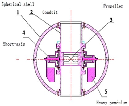
BYSQ-2 robot has only one propeller, which is located in the middle of the main body, and the catheter is fixedly connected with the spherical shell. The outer wall of the conduit mounts a sleeve called the long axis, which can rotate around the conduit. A short axis is perpendicular to the long axis, which is equipped with a rotatable weight pendulum mechanism. The control circuits and the driving motors of the robot are all installed in a sealed circular glass fiber shell. The physical parameters of BYSQ-2 prototype are shown in Table 1, and the structure is shown in Figure 1(a) and (b).
Table 1Parameters of the robot
Notion of parameter | Symbol of parameter | Value of parameter |
Propeller thrust | (–20 N, 20 N) | |
Pitching motor torque | (–20 N·m, 20 N·m) | |
Equivalent quality of spherical shell | 30 kg | |
Equivalent quality of heavy pendulum | 30 kg | |
Pendulum length | 0.2 m | |
Moment of inertia of spherical shell | 2 kg·m2 | |
Quadratic resistance coefficient | 15 | |
Additional mass | 15 kg | |
Swing angle | (π/2, –π/2) | |
Pitching angle | (π/2, –π/2) |
Fig. 1The structure and driving forces

a)
b)
c)
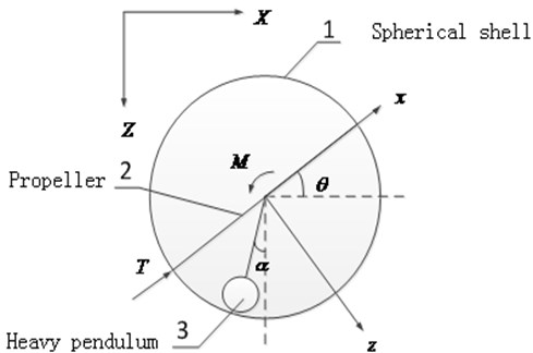
Usually the driving motor of the long axis needs to work only for inhibiting the roll and keeping the course. This movement of long axis does not cause fluctuations of the robot. In order to study the regular pitching movement and the horizontal accelerating movement in vertical plane, the robot is simplified to “propeller-pendulum” model, thus the structural features of the single propeller and heavy pendulum are highlighted. The degree of freedom of the long axis is ignored. The simplified structure of the longitudinal section is shown in Figure 1(b).
The methods of building robot’s dynamics model include mainly Kane's method, Lagrange method and Newton Euler method. Graver J. G., et al. (2005) built a modeling of underwater glider with a changing centroid through Newton Euler method, which has a clear physical meaning [22]. In the coordinate system fixed on robot, the speed of the underwater robot is , and in the inertial coordinate system, the underwater robot’s posture is . The dynamics equation is expressed as Formula (1):
where the left items of the equation in turn: inertial mass item, additional mass item, inertial Coriolis item, additional Coriolis item, quadratic resistance item, the gravity item and the buoyancy item; the right of the equation is the control force item.
In order to analyze the moving characteristics and facilitate the establishment of the dynamic model, the assumptions are made as follows according to the conditions of the actual operating environment and physical prototype:
• By the symmetrical design, the rotational inertia’s spindle of the spherical shell (including the structures fixed on the spherical shell) goes through the center of the sphere.
• The sphere structure of the shell makes the hydrodynamic non-coupling. Translational additional mass coefficient is equal along the three axes, and the rotational additional mass coefficient is very small and negligible.
• Because the velocity of the underwater robot is relatively low, it is reasonable to consider only second-order nonlinear translational resistance of the water, and the resistance coefficients along the three axes are equal.
According to the Formula (1), the dynamic equation of the shell in the vertical plane is obtained in the coordinate system of the robot, as shown in Equation (2):
where is the buoyant force, is the disturbing force generated by the heavy pendulum in axes, and is the disturbing force generated by the heavy pendulum in axes.
Similar to the bridge crane system (D. Blackburn, et al., 2008) [23, 24], the dynamic model of heavy pendulum can be obtained as shown in Equation (3):
The buoyancy of the robot is equal to the gravity, and the relationship of Formula (9) is obtained:
By combining equation (2), (3) and (4), the dynamic equation of the entire robot system in the vertical plane is obtained, as shown in Equation (5):
The speed of the robot is transformed into the inertial coordinate system by the kinematics relations (6):
3. Fluctuation analysis and simulation
When the robot moves in the water, the main power is supplied through the propeller in the conduit. The force is located in the center line of the cylindrical conduit, which passes the center of the sphere. The gravity of the robot (the gravity of spherical shell quality and the gravity of the pendulum quality) is equal to the buoyancy generated by the drainage of the spherical shell. In addition, the slow movement of the robot is affected by the viscous hydrodynamic and the inertial hydrodynamic. The inertia hydrodynamic force is proportional to the acceleration of the robot. And the viscous hydrodynamic basically is proportional to the square of the speed (ignoring the linear term). Accordingly, when the robot starts moving in the pitch angle 0 and the initial velocity 0, a simple expression of the acceleration is shown in Equation (7) below:
Assuming that the response time of the thrust is ignored at the initial moment, quickly reaches a predetermined value. According to the formula (7), with velocity increasing, the acceleration of the robot is gradually reduced to 0, and at last the robot should maintain a constant speed. However, the heavy pendulum destroys the state of equilibrium. When the robot is accelerating in the horizontal direction, the pendulum is not in the vertical direction, and it swings backwards to a certain angle , as shown in b) of Figure 1. The swing angle is restricted by gravitational torque, so it does not become very large. But with the acceleration changing, the swing angle also changes, which is the reason why the heavy pendulum swings in the acceleration process.
Robot often adjusts the pitching angle to complete the dive or float, and the main driving force is from the reaction torque of the motor driving heavy pendulum. Because the outer surface of the spherical shell is smooth, the viscous resistance and inertial resistance under the rotational movement have been ignored. The pitching movement of the robot is simply represented as Formula (8):
When the robot adjusts the pitching angle, the rotational acceleration of the pitching angle is proportional to the motor torque. The pitching angle has not the final stable value, which is different from the above acceleration state, so it is necessary to acquire an attitude signal of the gyro sensor as feedback for closed-loop control. At the same time the heavy pendulum will be affected by the motor torque, and it will rotate and swing-up to an angle in the opposite direction. And similar to the accelerated state the swing angle also is limited by gravitational torque. The closed-loop control of the motor will inevitably lead to the changes of the torque, and the swing angle of the heavy pendulum will continue to change. Above all this swing will also affect the stability of the robot.
If the swing of the heavy pendulum is not suppressed after the action of the acceleration or pitching, the fluctuation of the robot will continue for some time. In the horizontal direction the coupling relationship between the swing of the heavy pendulum and the acceleration of the robot can be expressed as the following Formula (9):
According to Equation (7), the swing angle will be affected by the acceleration of the robot. And the robot will also be affected by the disturbing force generated by the heavy pendulum. So it is closely related and mutual coupled between the swing of the heavy pendulum and the velocity fluctuation of the robot. Similarly, the robot will also produce such coupling fluctuations in the vertical direction.
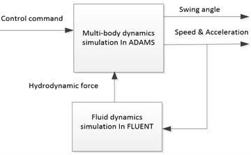
The simulation for the robot includes two aspects; one is the fluid dynamics simulation that is used to calculate the hydrodynamic coefficients. Another is multi-body dynamics simulation, which is used to calculate the interaction between the heavy pendulum and the main body of robot. So it is appropriate that Fluent software and Adams software are chosen to accomplish this work. The hydrodynamic results as constraints from Fluent software are loaded into the virtual prototype in Adams software. The structure of the simulation method is shown in Figure 2(a).
Fig. 2Structure of the simulation and calculation
a)
b)
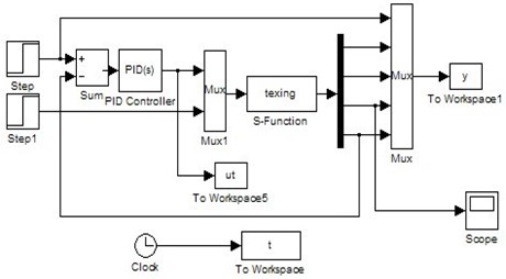
Compared with the simulation results, the theoretical results of the robot are calculated according to the dynamic equation (5) by Matlab. The output section of the state variable is transformed to the inertial coordinate system in S function by Equation (6). The structure of the calculation module is shown in Figure 2(b).
The PID parameters for the pitching control are set, 0.5, 0, 2. Two conventional moving processes are simulated and calculated as follows:
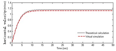
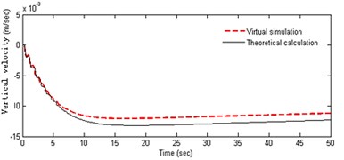
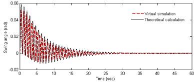
• The robot starts by 20 N horizontal thrust at the initial time, and the pitching angle maintains in horizontal direction. The velocity and swing angle are shown in (a), (b) and (c) of Figure 3.
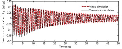
• The robot adjusts pitching angle from 0 to 45 degrees in the initial static conditions, and the horizontal thrust is 0 N. The velocity and swing angle are shown in (d), (e) and (f) of Figure 3.
Fig. 3The simulation and calculation
a)
b)
c)
d)
e)
f)
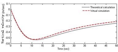
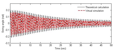
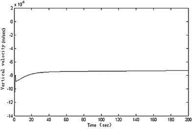
In Figure 3(a-b), it can be obtained that the acceleration of the robot is variable in the starting process. The horizontal velocity becomes stable at about 1.1 m/s after 10 s, and the fluctuation can be seen obviously in the acceleration phase. At the initial moment the heavy pendulum swings significantly. The centerline of the swing is not in vertical line, and the initial swing direction is opposite to the direction of the acceleration of the robot. As can be seen from Figure 3(c-f), the amplitude of the velocity fluctuation is very more obvious in the process of adjusting the pitching angle, and especially the fluctuation law is very consistent with the weight pendulum swinging. Robot has a small velocity in the vertical direction, which decreases slowly and becomes stationary with the swinging amplitude getting small. Observing the curves in Figures 3(a) and (d), it can be seen that the fluctuation amplitude of the speed in pitching process is significantly greater than that in accelerating process, and the convergence is slow. However, the fluctuation frequency is almost equal and positively correlated with each other, and there is basically the same attenuation law. The above analysis shows the coupling relationship between the angle of the pendulum and the speed of the robot. Both theoretical calculations and the results of simulation experiments are similar, which proves the correctness of the theoretical model. Further, it can be inferred that the cyclical horizontal acceleration and pitching adjustment may result in instability of the robot.
4. Analysis of influence factors
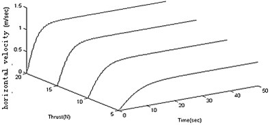
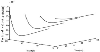
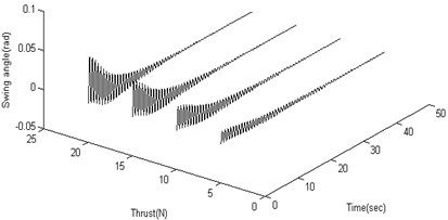
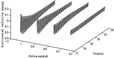
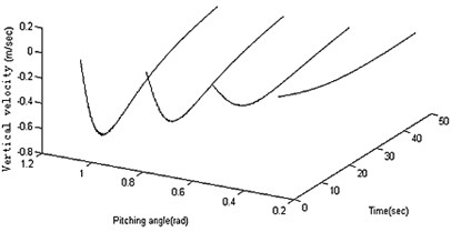
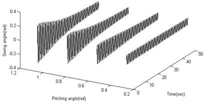
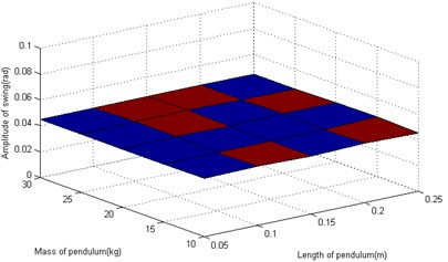
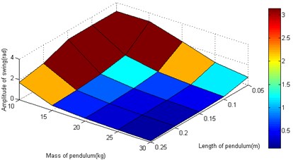
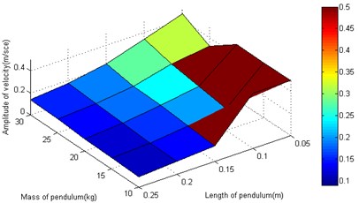
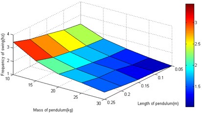
Figure 3 shows the results of 20 N horizontal thrust and 45 degrees pitching angle. To study the vertical moving characteristics of the robot, the output results in different moving parameters are summarized. In different conditions of propulsive forces, the feature data is calculated as shown in Figure 4(a), (b) and (c). In different conditions of pitching angles, the feature data is calculated as shown in Figure 4(d), (e) and (f). It can be derived from above figures the amplitudes get larger with the propulsion force and the pitching angle increasing.
Fig. 4Analysis for different motion parameters
a)
b)
c)
d)
e)
f)
Fig. 5Analysis for different structural parameters
a)
b)
c)
d)
The motion parameters are the same as that in section 3. In the starting and pitching processes of the robot, the swing is simulated and calculated in the conditions of the different structural parameters. The amplitude and frequency for heavy pendulum swinging are analyzed. The total mass (including heavy pendulum and shell) is a constant value, so only two structural parameters (the quality and length of the pendulum) are retained. When the robot speeds up in the horizontal, the swinging amplitude is independent of the structural parameters as shown in Figure 5(a). When the robot adjusts the pitching angle, the swinging amplitude closely related with the structural parameters, and the amplitude gets larger with the mass and length of the pendulum increasing as shown in Figure 5(b). The length and quality of pendulum are not too small, or else the swinging value is greater than π, which is not stable. As shown in Figure 5(c), the length of the pendulum closely affects the fluctuation of robot. In order to prevent the velocity from fluctuations, it is a good choice to increase the pendulum’s length, and the pendulum’s quality affects little. The swinging frequency also closely related with the structural parameters, and the frequency gets larger with the mass and length of the pendulum increasing as shown in Figure 5(d).
Through the theoretical calculations and simulations for the spherical robot’s accelerating and pitching process, the coupling fluctuation features in vertical plane are analyzed and summarized. Further research shows that it is important to suppress the fluctuation by selecting the controlling process and increasing the pendulum’s length. Because the robot's structure has been determined, the controller needs to be designed reasonably.
5. Pitching controller
When the robot collects data under water, the pitching angle often needs to be constantly adjusted, and the speed of the robot needs to maintain a constant. However, the structure of this the pendulum may cause instability of the robot, and the swing will take up valuable space within the robot. In order to suppress the undesirable fluctuations, a controller for suppressing swing is designed. The dynamic Equation (5) is transformed into system (10), which is an underactuated system:
In order to achieve the stable control, the swing of the pendulum needs to be quickly suppressed, while the robot's pitching angle must meet the desired goals. Thus the pitching angle, the pitching angular velocity, the swing angle and the swing angular velocity are measured as the state variables . In order to design the primary sliding surface, the system (9) is decomposed into two subsystems (11a) and (11b):
where , , , , .
Subsystem 1 is a control equation for pitching, and the pitching angle error is set , the primary sliding surface 1 of subsystem 1 is designed as follows:
Subsystem 2 is the swinging equation of the pendulum. In order to suppress swinging interference, the pendulum need to be controlled in a vertical line, so the primary sliding surface 2 of subsystem 2 is designed as follows:
In order to make the two subsystems eventually converge, the ultimate sliding surface is designed as follows:
In order to ensure the ultimate sliding surface converging, the control rate is taken as:
In Formula (16) the control items include certainties and uncertainties. In order to make the robot system moves along a sliding surface, the additional switching control must be added, so the total control rate includes the following three components:
where , , .
The interference includes uncertainties of the speed, uncertainties of the thrust, uncertainties of hydrodynamics, uncertainties of external disturbance torques and other factors. If these uncertainties are not compensated, the switching gain coefficient will be large, and the switching operation is frequent, which will cause chattering even instability. Therefore, RBF neural network (18) is used to estimate the amount of these uncertainties, and its approximation performance plays an impotent role in compensating interference:
where is the optimal weight for the network; is the network approximation error; and are the optimal parameters for the Gaussian function.
is taken as neural network input, and the network output as follows:
where is the compensation value of network output; , , are the estimation of network parameters. The compensation and estimation errors are show as follow:
The Formula (19) in the approximated point is expanded into the Formula (21) by multivariate Taylor series:
The three variable parameters of neural network adjust the adaptive rate according to the following formula:
where , and are positive numbers.
The switching gain is difficult to determine. If the gain value is too large, the control system will produce great chattering, but too small, not stable. So the gain needs to be designed adaptively:
where is the optimal value of the gain; is the estimated value of the gain; is the evaluated error; are a positive number.
Fig. 6The structure of the controller
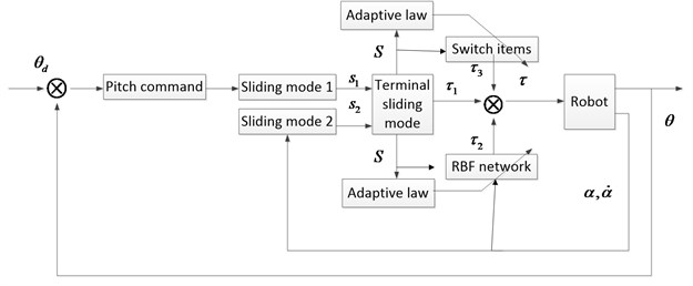
Based on the above design, the pitching controller of the spherical AUV is obtained. The overall structure is shown in Figure 6:
The goal of designing controller is to make the robot system complete certain pitching movement, while the swing angle of heavy pendulum is as small as possible.
Theorem 1: under the action of the control law (17), adaptive law (22) and (24), the ultimate sliding surface (14), neural network compensation (18) and adaptive gain (22) of the system (10) are asymptotically stable.
Proof: Lyapunov function is constructed as follows:
The formulas (15), (20) and (23) are brought into (26):
The formulas (21) is brought into (27):
The formulas (22) and (24) are brought into (28):
Because is a small amount of higher order, can be obtained:
Theorem 2: the ultimate sliding surface (14) is bounded and asymptotic convergence. At the same time, the subsystem sliding surface (12a) and (13a) are asymptotic convergence.
Proof: by Theorem 1, is bounded and asymptotic convergence, and two ultimate sliding surfaces are built by taking different parameters, which respectively satisfy Theorem 1.
The difference between the two sliding surfaces (31) is integrated:
According to Barbalat theorem, the result (33) can be obtained:
The sum between the two sliding surfaces (31) is integrated:
According to the result (33) and Barbalat theorem, , and in a similar way, .
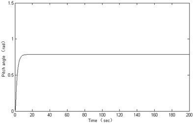
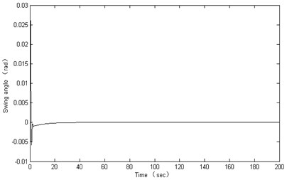
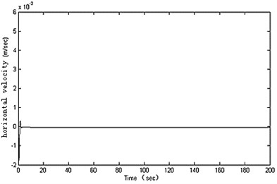
In the simulation experiments for pitching control, the RBF neural network is designed with input layer 2 nodes, hidden layer 10 nodes and output layer 1 node. 0.7, 20, 0.8, , and the other parameters are set in accordance with Table 1. The control results are shown in Figure 7.
As can be seen from the simulation results, the designed controller can realize an excellent dynamic performance for the robot’s pitching movement. The swinging angle is inhibited and quickly converged to zero, and the robot’s fluctuates reduces significantly. At the same time, the stability of the robot at low speed was greatly improved in the water-tank experiment. So the proposed method can ensure the robot moving stably.
Fig. 7Results for pitching control
a)
b)
c)
d)
6. Conclusion
As a new type of underwater spherical robot, BYSQ-2 has only one propeller and uses the heavy pendulum to adjust attitude. The robot moves flexibly at low speed, and the ability of resisting pressure is good. This paper researched the motion characteristics of the robot with a heavy pendulum in the vertical plane, and found the coupling fluctuation law in the accelerating and pitching process:
• The heavy pendulum will swing when the robot is accelerating and pitching, but the swing phenomenon is more obvious in the process of pitching.
• The swing of heavy pendulum will cause fluctuations, and the horizontal velocity of the robot has larger fluctuation.
• The amplitude of the coupling fluctuation is affected closely by motion parameters, and it gets larger with the motion parameters increasing.
• In the process of pitching, the angle amplitude of the pendulum swinging becomes large with the heavy pendulum’s length and mass decreasing. But in the process of accelerating it is independent of the structural parameters.
• The coupling fluctuation frequency is independent of the robot's motion parameters, but it will become larger with the pendulum’s length increasing and the pendulum’s quality decreasing.
• In the process of pitching, the velocity fluctuation amplitude becomes small with the heavy pendulum’s length increasing, but the pendulum’s mass affects little.
According to the above conclusions, it is necessary to increase the pendulum’s length, and it is also necessary to design controller for suppressing fluctuations. In order to reduce the coupling fluctuation and improve the stability of the robot for such underactuated system. This paper proposed a pitching controller based on neural network and adaptive sliding mode. The good results were shown for suppressing coupling fluctuation by simulation experiment, but the configuration and adjustment of control parameters are relatively difficult. Therefore, it is important to simplify the structure of the controller. At the same time, the horizontal steering structure needs to be designed better and the motion characteristics in horizontal plane need to be analyzed in future.
References
-
U. S. Department of the Navy. The navy unmanned undersea vehicle (UUV) master plan, 2004.
-
Ridao P., Batlle J., Carreras M. Model identification of a low-speed UUV. Proceedings of the 1st IFAC Workshop on Guidance and Control of Underwater Vehicles, UK, 2003, p. 47-52.
-
Storkersen N., Kristensen J., Indreeide A., Seim J., Glancy T. Hugin-UUV for seabed surveying. Sea Technology, Vol. 39, Issue 2, 1998, p. 99-104.
-
Naylies I. The sensory requirement of a PC controlled AUV. Master’s thesis, Offshore Technology Centre, Cranfield University, 2000.
-
Bachmayer R., Leonard N. E., Graver J., Fiorelli E., BhaRa E, Paley D. Underwater gliders: recent developments and future applications. Proc. of 2004 International Symposium on Underwater Technology, Taipei Taiwan, 2004, p. 195-200.
-
Jason E, Meyer N. Dynamics modeling and performance evaluation of an autonomous underwater vehicle. Ocean Engineering, Vol. 31, Issue 14-15, 2004, p. 1835-1858.
-
Shu-xin W, Xiu-jun S, Yan-hui W, Jian-guo W, Xiao-ming W. Dynamic modeling and motion simulation for a winged hybrid-driven underwater glider. China Ocean Engineering, Vol. 1, Issue 25, 2011, p. 97-112.
-
Choi H. T., Hanai A., Choi S. K., Yuh J. Development of an underwater robot, ODIN-III. IEEE International Conference on Intelligent Robots and Systems, 2003, p. 836-841.
-
Do K. D., Jiang Z. P., Pan J., Nijmeijer H. Global output feedback universal controller for stabilization and tracking of underactuated ODIN-an underwater vehicle. Proc. of the IEEE Conference on Decision and Control, 2002, p. 504-509.
-
Simon A. Watson, Dominic J. P. Crutchley, Peter N. Green The design and technical challenges of a micro-autonomous underwater vehicle (μAUV). Proc. of the 2011 IEEE International Conference on Mechatronics and Automation, Beijing, China, 2011, p. 567-572.
-
Simon A. Watson, Peter N. Green. A de-coupled vertical controller for micro-autonomous underwater vehicles (μAUVs). Proc. of the 2011 IEEE International Conference on Mechatronics and Automation, Beijing, China, 2011, p. 561-566.
-
Guo S., Lin X., Tanaka K., Hata S. Modeling of water-jet propeller for underwater vehicles. Proc. of the 2010 IEEE International Conference on Automation and Logistics, 2010, p. 92-97.
-
Guo S., Lin X., Tanaka K., Hata S. Development and control of a vectored water-jet based spherical underwater vehicle. Proc. of the 2010 IEEE International Conference on Information and Automation, 2010, p. 1341-1346.
-
Xichuan L., Shuxiang G. Development of a spherical underwater robot equipped with multiple vectored water-jet-based thrusters. Journal of Intelligent & Robotic Systems, Vol. 67, 2012, p. 307-321.
-
Xiaojuan L., Hanxu S., Qingxuan J. The hydrodynamic analysis for the underwater robot with a spherical hull. Proc. of SPIE – The International Society for Optical Engineering, Space Exploration Technologies II, Orlando, USA, Vol. 7331, 2009, p. 1-8.
-
Xiaojuan L., Hanxu S., Qingxuan J. Principle and dynamic analysis of a new-type spherical underwater vehicle. Journal of Beijing University of Posts and Telecommunications, Vol. 33, Issue 3, 2010, p. 20-23, (in Chinese).
-
Utkin V. I. Variable structure systems with sliding modes. IEEE Transactions Automatic Control, Vol. 22, Issue 2, 1977, p. 212-222.
-
Munoz D., Sbarbaro D. An adaptive sliding-mode controller for discrete nonlinear systems. IEEE Transactions on Industrial Electronics, Vol. 47, Issue 3, 2000, p. 574-581.
-
Mon Y.-J., Lin C.-M. Hierarchical fuzzy sliding-mode control. Proc. IEEE World Congress on Computational Intelligence, 2002, p. 656-661.
-
W. Wang, J. Yi, D. Zhao, D. Liu Design of a stable sliding-mode controller for a class of second-order underactuated systems. IEEE Proc. – Control Theory Appl., Vol. 6, Issue 151, 2004, p. 683-690.
-
Mohamed B. Trabia, Jamil M. Renno, Kamal A. F. Moustafa Generalized design of an anti-swing fuzzy logic controller for an overhead crane with hoist. Journal of Vibration and Control Online First, 2008.
-
Graver J. G. Underwater Glider: Dynamics, Control and Design. Ph. D. Thesis, Princeton University, 2005.
-
Abdel-Rahman E. M., Nayfeh A. H., Masoud Z. N. Dynamics and control of cranes: a review. Journal of Vibration and Control, Vol. 9, Issue 7, 2003, p. 863-908.
-
D. Blackburn, W. Singhose, J. Kitchen, V. Patrangenaru, J. Lawrence, Tatsuaki Kamoi, Ayako Taura Command shaping for nonlinear crane dynamics. Journal of Vibration and Control, originally published online, 2009.
About this article

The authors would like to thank the support of China National Natural Science Foundation (51175048) for the research.
