Abstract
Taking a rotor-bearing system attached with two discs as a research object, the effect of axial locations of two discs on the oil-film instability is investigated under out-of-phase unbalance of two discs. The nonlinear dynamic behavior of the rotor bearing system is analyzed by applying a finite element method (FEM). The left and right sliding bearings are simulated by an unsteady nonlinear oil-film force model based on the assumption of short bearings, respectively. The paper mainly focuses on the second oil-film instability law with two changing methods of disc locations and the complicated nonlinear responses of the rotor system are also analyzed through the amplitude-frequency response of oil-film force from the right bearing, spectrum cascades diagram. The results show that the phenomena of the first and second mode oil-film instabilities have more to do with the natural frequencies and the characteristics of oil-film force of the left or right bearing. When the second natural frequency is lower and the right disc is close to the oil-film bearing, the oil-film force will become larger, which will cause oil-film instability violently. The results have an important significance for the fault diagnosis of oil-film instability and structural design of bearing-rotor system with this type.
1. Introduction
Oil-film instability can cause severe rotor vibration in large rotating machinery mounted on sliding bearings, which limits the safe and efficient operation of rotor systems. Hence, it becomes a substantial concern for industry and it is rather necessary to get a better understanding the mechanism for providing an efficient technical support for diagnosing system malfunctions about oil whirl/whip, while the installation condition is one of the influence parameters to affect the oil-film instability law.
Nonlinear oil-film force is the main reason of oil-film instability. It is very important to get an analytical formula of oil-film force for the global study of the mechanism of the nonlinear instability. Modern turbine generators are becoming larger span and more flexible and the linear oil-film force model based on eight-coefficient is unacceptable to explore the nonlinear behaviors of the system [1]. Muszynska, et al. [2-3] presented a nonlinear oil-film force model, considering fluid circumferential average velocity of the flow, based on a series of experimental results. Based on the short bearing approximation of Ocvirk [4], Capone [5, 6] presented a nonlinear oil-film model and analyzed the orbits of the shaft in the bearings by the model. Based on Capone model, the nonlinear dynamic behaviors of a rotor-bearing system were investigated [7-10]. Because the steady oil-film model ignores the effect of the unsteady motion of the journal, Zhang, et al. [1] presented a general mathematical expression of unsteady nonlinear oil-film force model. By using the non-steady nonlinear oil-film force model presented by Zhang [1], Xu, et al. [11] discussed the stability of a rigid Jeffcott rotor supported by short journal bearing. By compared with steady oil-film model, their results showed that the oil-film modal adopted in the paper is more suitable for rotor dynamic application. Ding, et al. [12] analyzed non-stationary processes of a rotor-bearing system.
The bearing parameters, such as the length-to-diameter ratio, bearing radial clearance, oil viscosity, etc., are also important factors affecting the oil-film instability and a lot of researches have been performed [13-16]. These studies provided a better understanding of the impact of the bearing factors on instability of rotor system and played a guiding role for future design of rotor system.
Except for the oil-film force and bearing parameters, there are many factors that can cause oil-film instability in a rotor bearing system. Many theoretical studies, numerical simulations and experiments have been carried out to reveal the effect of the rotating speed on the oil-film instability due to seals or bearings [17-24]. The effects of eccentricity [25, 26], unbalance [13, 27-29], shaft length [30], disc location [27, 30] and phase angle between the eccentricities of disks [31, 32] on the dynamic characteristics of the system have also been investigated. Furthermore, Subbiah [33] has found oil whirl/whip also occurred at increased turbine MW loading, which means oil whirl/whip could also be load-dependent. Based on above researches, a more comprehensive understanding for the dynamic characteristics of rotor systems can be acquired.
Most works already done are mainly concerned about the first mode whirl/whip and the effects of rotating speed, unbalance and bearing parameters on it. Although the experiments in Refs. [3, 34-36] showed the presence of second mode whirl/whip, the researches on high order mode whir/whip (bending modes) by numerical simulation are still very limited, and the coupling mechanism between the parameters (the rotor structure parameters and unbalance) and the second mode whirl/whip is also seldom reported.
In this paper, influences of the locations of two discs on the second mode whirl/whip and the instability mechanism of the rotor-bearing system, attached with two disks, are investigated under out-of-phase unbalances of two discs condition. A non-steady nonlinear oil-film force model under short bearing assumption [1] is adopted. The dynamical equations of motion are numerical simulated and the spectrum cascades are used to illustrate the nonsynchronous vibration.
This paper consists of four sections. After this introduction, a dynamic model of a rotor-bearing system with two discs is proposed in Section 2. In Section 3, dynamic characteristics of the rotor-bearing system are analyzed with two changing methods of disc locations under out-of-phase unbalances of two discs. Finally, conclusions are drawn in Section 4.
2. Dynamic equation of the system
In order to research the rotor-bearing system efficiently, the finite element (FE) model of the rotor-bearing system is simplified according to the following assumptions:
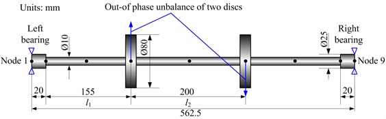
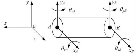
a) The schematic of the rotor system, nodes and elements is shown in Fig. 1. The shaft is divided into 8 Timoshenko beam elements and 9 nodes. It is worth noting that the number of elements is chosen to ensure a sufficient level of accuracy in the results and computational efficiency. Meanwhile, the element model is shown in Fig. 2. In the figure, , and , denote displacements in translation directions and angular displacements in rotation directions, subscripts and denote nodes and respectively.
Fig. 1Schematic of the rotor system, nodes and elements
b) The discs are simulated by lumped mass elements, which are superimposed upon the corresponding nodes and specified by the mass , the diametral and polar moments of inertia ( and ) and the gyroscopic effects of the discs are also considered. The detailed information about the lumped mass element is shown in Ref. [37]. In this paper, two discs are identical and 0.5919 kg, 2.5×10⁻⁴ kg∙m2 and 4.7×10⁻⁴ kg∙m2.
c) The two sliding bearings (see Fig. 1) are simulated by a nonlinear oil-film force model [1].
Fig. 2FE model of a shaft element
The general displacement vector of a beam element for the shaft is given as:
where the superscript stands for an element. The mass, stiffness and gyroscopic matrices of each shaft element are denoted as , , and , respectively [37].
The dynamic equations of the rotor-bearing system with thirty-six degrees of freedom can be deduced as follows:
where , , , and are the mass matrix, gyroscopic matrix, damping matrix, stiffness matrix and displacement vector of the system, , and the vector of eccentric force, oil-film force and gravity force of the rotor bearing system, respectively.
For Eq. (2), the Newmark- integration method is adopted to solve the equation because it is a robust algorithm to solve nonlinear equations in the time domain [38]. The format of Newmark- is:
where and are adjustable parameters depending on the required precision and stability of the numerical integration, is the integration step. The following formula can be derived from Eq. (3):
Substituting Eq. (4) into the dynamic equilibrium equations Eq. (2), it will be:
here, and . Eq. (5) can be simplified as follows:
where:
The solution of the equations will be unconditionally stable when the Newmark integral parameters meet the following conditions:
The spectrum cascade is used to show the change of the frequency components with different disc positions. In order to understand the vibration intensity of the rotor system intuitively, the vibration responses of the system are presented by dimensional forms.
In practical engineering, most structures are multiple-degree-of-freedom systems, whose damping is mostly based on Rayleigh damping theory, namely the damping matrix is obtained by superposition of mass matrix and stiffness matrix. This simulation method of energy dissipation has a lot of numerical advantages, and it can meet the needs of general structure dynamic analysis. In this paper, Rayleigh damping form is applied by the following formula [39]:
where and are the first and second order natural frequencies (rev/min); and are the first and second order modal damping ratios, respectively. In this paper, 0.02 and 0.04.
2.1. Nonlinear oil-film forces
The self-excited vibration, known as “whirl”, “whip”, or simply “instability”, will occur due to the presence of nonlinear fluid forces when the rotating speed exceeds a threshold speed [40]. Specially, the second mode instability appears when the rotating speed exceeds twice the second natural frequency.
The support of the bearing is simulated by a non-steady nonlinear hydrodynamic force model deduced by Zhang [1], which is able to simulate the dynamic behavior of fluid-induced instabilities. The oil-film forces are treated as external excitation and superimposed upon the corresponding degrees of freedom (node 1 and node 9). For short bearing, the oil-film inside bearing rotating with the shaft causes reactive hydrodynamic forces and in and directions which can be calculated by:
where represents the viscosity of lubricating oil. , and are length, diameter and mean radial clearance of the sliding bearing, respectively. In this paper, 25 mm and 0.3 mm. The dimensionless hydrodynamic forces and are calculated by the mathematical model [1].
2.2. Dimensionless equation of motion
In order to facilitate calculation and avoid excessive truncation errors, the dimensionless transformations are given as follows:
Substituting Eq. (13) into Eq. (2), the dynamic equations of the system can be rewritten in dimensionless form:
3. Numerical simulation of different disc locations under out-of-phase unbalance of two discs
Based on Refs. [32], the out-of-phase unbalance of two discs easily causes the second mode instability. So in this paper, only the out-of-phase unbalance of two discs is considered to focus on the mechanism of second mode instability. The unbalance moments of two discs are all assumed as 1.1838×10⁻⁴ kg∙m, then two changing methods of disc locations are applied to ascertain their influences on the dynamic behavior and the first/second mode instability thresholds of the rotor system. In the case of constant shaft length, 562.5 mm, the two simulations are given as follows:
1) The simulation 1 is that the position of the left disc does not change (i.e., 155 mm is constant) while the distance between the left and right discs changes from 40 mm to 280 mm with 40 mm interval (see Fig. 1).
2) The simulation 2 is defined as keeping the distance of two discs constant (i.e., 200 mm is constant) and changing the distance between the left disc and left sliding bearing from 40 mm to 280 mm with 40 mm interval (see Fig. 1).
Table 1Natural frequencies of the system under two simulations
Simulation 1 | (mm) | The first natural frequency (Hz) | The second natural frequency (Hz) |
40 | 24.82 | 174.83 | |
80 | 24.34 | 152.26 | |
120 | 24.40 | 126.28 | |
160 | 24.99 | 108.22 | |
200 | 26.13 | 97.34 | |
240 | 27.82 | 92.62 | |
280 | 29.96 | 95.23 | |
Simulation 2 | (mm) | The first natural frequency (Hz) | The second natural frequency (Hz) |
40 | 28.98 | 148.67 | |
80 | 27.42 | 115.03 | |
120 | 26.46 | 101.21 | |
160 | 26.12 | 97.73 | |
200 | 26.42 | 100.72 | |
240 | 27.34 | 113.75 | |
280 | 28.87 | 145.64 |
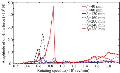
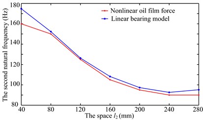
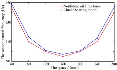
Amplitude-frequency responses of right bearing oil-film force in direction under two simulations are shown in Fig. 3. It is clear that the second loading condition mainly excites the second frequency. The larger peaks in Fig. 3 are used to obtain the second natural frequencies under different disc locations, and the natural frequencies under two simulations are shown by the red dotted line in Fig. 4. In order to verify the results determined by peak points, the system natural frequencies are calculated by linear bearing stiffness (see the blue dotted line in Fig. 4), where the two bearing stiffness are all assumed as 1×10⁸ N/m in and directions. Based on the linear bearing model, the first two order natural frequencies are listed in Table 1. It can be seen from Fig. 4 and Table 1 that the second natural frequencies of the system determined by the peak points is slightly less than those by linear bearing model because there is some error between the bearing stiffness determined by nonlinear oil-film force and the assumed stiffness. Considering the model symmetry of bearings and discs, the system natural frequencies at two sides of 160 mm are almost the same under the simulation 2, namely the natural frequency at 40 mm is close to that at 280 mm (see Fig. 1).
Fig. 3Amplitude-frequency responses of right bearing oil-film force in y direction under two simulations

a) Simulation 1
b) Simulation 2
Fig. 4The second natural frequencyunder two simulations
a) Simulation 1
b) Simulation 2
3.1. Simulation 1
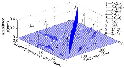
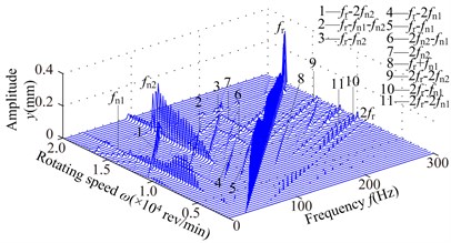
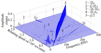
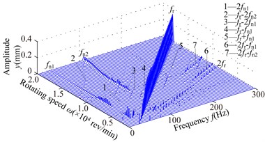
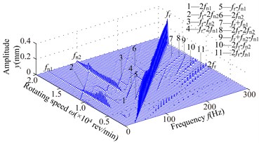
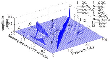
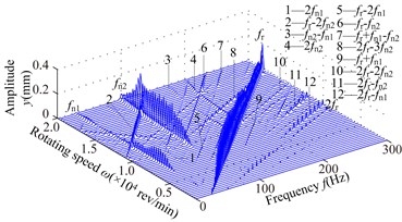
The spectrum cascades of right bearing (node 9) with different under the simulation 1 are displayed in Fig. 5. In the figure, the interval of rotating speed is 300 rev/min. These figures show the following dynamic phenomena.
1) At 40 mm, the first mode whip appears at about 4800 rev/min and it is violent in the range of the rotating speed [4800, 8400] rev/min and disappears at higher rotating speed (above 17000 rev/min). The second oil whirl appears at about 12300 rev/min and disappears at about 15000 rev/min. At 80 mm, the second mode whirl becomes the second mode whip and its frequency is locked at about 137 Hz, which is slightly less than the natural frequency 150 Hz (see Fig. 4(a)). With increasing , the range of the second mode whip increases and its amplitude gradually increases; the amplitudes of and are close at 120, 160 mm (see Figs. 5(c), 5(d)) and the second mode whip becomes evident at higher rotating speed at 200, 240, 280 mm (see Figs. 5(e), 5(f), 5(g)).
2) With the increase of , the combination frequency components about and are more complicated, and the whip amplitude is greater than that of rotating speed under some conditions, such as the amplitude of (see Fig. 5(a)) and the amplitude of (see Figs. 5(f), 5(g)). The transfer of vibration energy among , and can be observed, such as the large amplitude of in the range of [6900, 10200] rev/min, the large amplitude of in the range of [11400, 16800] rev/min and the large amplitude of in the range of [16800, 19800] rev/min (Fig. 5(e)).
3) The larger will lead to the smaller second natural frequency (see Fig. 4), which results that the second mode instability is excited easily and the system vibration becomes fierce gradually.
3.2. Simulation 2
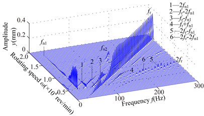
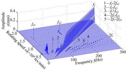
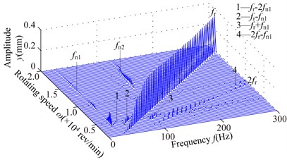
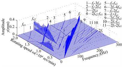
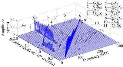
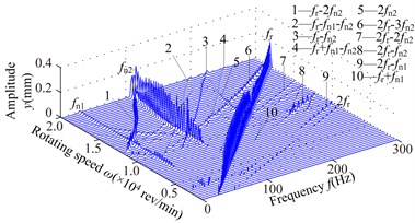
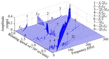
Under the simulation 2, the spectrum cascades of right bearing (node 9) in direction are illustrated in Fig. 6, which exhibits the following dynamic phenomena.
1) At 40 mm, the first mode whip appears at about 3300 rev/min and it is dominated in the range of the rotating speed [3300,6000] rev/min. frequency component appears in the range of [12300,13800] rev/min, and frequency component slightly greater than in the range of [12600,15300] rev/min, and the second oil whip appears at about 17400 rev/min. Considering the model symmetry of bearings and discs, the frequency components at 280 mm are very similar to those at 40 mm except for the amplitude. At 80 mm, the second mode whip is locked at about 100 Hz, which is slightly less than the natural frequency 115 Hz (see Fig. 4(b)). With increasing , the range of the second mode whip increases and its amplitude also increases gradually (160 mm).
2) Compared with the simulation 1, it is obvious that the frequency components are very similar when the structure sizes are approximate, such as 200 mm in simulation 1 and 160 mm in simulation 2. The second mode whip is more serious and the oil-film force becomes larger when the discs are close to the right bearing.
3) The second natural frequency decreases to a minimum value at 160 mm and then increases with the increasing (see Fig. 4). Obviously, when 40 and 280 mm, the second natural frequency is higher than that at other disc locations. Hence, the second instability is hardly excited.
Fig. 5Spectrum cascades of the right bearing in y direction under the simulation 1: a) l2= 40 mm, b) l2= 80 mm, c) l2= 120 mm, d) l2= 160 mm, e) l2= 200 mm, f) l2= 240 mm, g) l2= 280 mm
a)
b)
c)
d)
e)
f)
g)
Fig. 6Spectrum cascades of the right bearing in y direction under simulation 2: a) l1= 40 mm, b) l1= 80 mm, c) l1= 120 mm, d) l1= 160 mm, e) l1= 200 mm, f) l1= 240 mm, g) l1= 280 mm
a)
b)
c)
d)
e)
f)
g)
3.3. Discussion of simulations 1 and 2
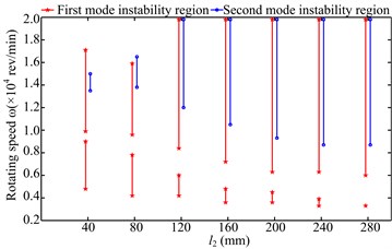
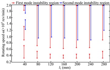
The instability regions under two simulations are shown in Fig. 7, which intuitively depicts the change of oil-film instability at different physical dimensions of the rotor system. By combining the spectrum cascades and instability regions shown in Fig. 7, some physical phenomena can be summarized as follows:
1) The first instability region shows a wide range under two simulations when the second natural frequency of the rotor system is large, such as 40, 80 mm and 40 mm. In these three cases, the second mode whirl appears at 40 mm and 40 mm, the second instability regions are relatively small and the rotating frequency is significantly large at higher speed.
2) With increasing in simulation 1, the first parts of the first mode instability regions gradually decrease; the threshold of its second parts gradually decreases and become stable at 200, 240, 280 mm; the beginning of the second mode instability also decreases gradually and then keeps stable. With increasing under the installation condition 2, the system instability regions are basically symmetrical about 160 mm, the change law of instability regions is similar to that under simulation 1 when changes from 40 mm to 160 mm.
3) The change of the instability regions is closely related to the natural characteristics of the system. The second oil whirl may appear when the second natural frequency is large and the range of the second mode instability regions increase. The whip amplitude becomes large when the discs are close to the right bearing and the second natural frequency decreases.
4) Under some structure sizes, the transfer of vibration energy among , and can be observed with the increasing rotating speed, such as Figs. 5(e) and 6(d).
Fig. 7Instability regions under two simulations: a) simulation 1, b) simulation 2
a)
b)
4. Conclusions
In this paper, a flexible rotor-bearing system attached with two discs is modeled by FEM and the system dynamic characteristics are simulated with two changing methods of disc locations under out-of-phase unbalance of two discs. Some conclusions can be summarized as follows:
1) The first mode instability is dominant, the second mode whirl may appear and the first two orders mode instability may disappear at higher rotating speed when the space between the two discs is smaller in simulation 1, and the second natural frequency is large in this case. The first parts of the first mode instability regions and the thresholds of its second parts gradually decrease, furthermore, the second mode instability regions gradually increase. The change of the instability regions is closely related to the natural characteristics of the system.
2) The amplitude of the second mode whip becomes large when the second natural frequency is lower and the discs are close to the right bearing, which is caused by the increase of oil-film force of the right bearing. Under some structure sizes, the transfer of vibration energy among rotating frequency, the first mode whip frequency and the second mode whip frequency can be observed with the increasing rotating speed.
References
-
Zhang W., Xu X. Modeling of nonlinear oil-film force acting on a journal with unsteady motion and nonlinear instability analysis under the model. International Journal of Nonlinear Sciences and Numerical Simulation, Vol. 1, Issue 3, 2000, p. 179-186.
-
Muszynska A., Bently D. E. Anti-swirl arrangements prevent rotor/seal instability. Journal of Vibration, Acoustics Stress and Reliability in Design, Vol. 111, Issue 2, 1989, p. 156-162.
-
Muszynska A. Rotordynamics. CRC Taylor & Francis Group, New York, 2005.
-
Ocvirk F. W. Short-bearing approximation for full journal bearings. National Advisory Committee for Aeronautics, TN 2808, 1952.
-
Capone G. Orbital motions of rigid symmetric rotor supported on journal bearings. La Meccanica Italiana, Vol. 199, Issue 199, 1986, p. 37-46.
-
Capone G. Analytical description of fluid-dynamic force field in cylindrical journal bearing. L’Energia Elettrica, Vol. 3, Issue 3, 1991, p. 105-110.
-
Jing J. P., Meng G., Sun Y., et al. On the non-linear dynamic of a rotor-bearing system. Journal of Sound and Vibration, Vol. 274, Issue 3, p. 2004, p. 1031-1044.
-
Jing J. P., Meng G., Sun Y., et al. On the oil-whipping of a rotor-bearing system by a continuum model. Applied Mathematical Modelling, Vol. 29, Issue 5, 2005, p. 461-475.
-
Adiletta G., Guido A. R., Rossi C. Nonlinear dynamics of a rigid unbalanced rotor in journal bearings. Part I: theoretical analysis. Nonlinear Dynamics, Vol. 14, Issue 1, p. 1997, p. 57-87.
-
Ding Q., Leung A. Y. T. Numerical and experimental investigations on flexible multi-bearing rotor dynamics. Journal of Vibration and Acoustics, Vol. 127, Issue 4, p. 2005, p. 408-415.
-
Xu X. F., Zhang W. Bifurcation and chaos of rigid unbalance rotor in short bearings under an unsteady oil-film force model. Journal of Vibration Engineering, Vol. 13, Issue 2, 2000, p. 247-252.
-
Ding Q., Leung A. Y. T. Non-stationary processes of rotor/bearing system in bifurcations. Journal of Sound and Vibration, Vol. 268, Issue 1, 2003, p. 33-48.
-
de Castro H. F., Cavalca K. L., Nordmann R. Whirl and whip instabilities in rotor-bearing system considering a nonlinear force model. Journal of Sound and Vibration, Vol. 317, Issue 1, 2008, p. 273-293.
-
Liu S., Chen J., Wang F., et al. Analysis and treatment of oil whirl on ultra-supercritical 1000 MW unit. The 8th IFToMM International Conference on Rotor Dynamics, Seoul, 2010, p. 579-583.
-
Zhao X. J., Hong H., Xu S. Y. Influence of the floating-ring bearing parameters on stability of turbocharge rotor-bearing system. The 4th International Symposium on Fluid Machinery and Fluid Engineering, Beijing, China, 2008, p. 421-425.
-
Schweizer B. Total instability of turbocharger rotors-physical explanation of the dynamic failure of rotors with full-floating ring bearings. Journal of Sound and Vibration, Vol. 328, Issue 1, 2009, p. 156-190.
-
Cheng M., Meng G., Jing J. P. Numerical and experimental study of a rotor-bearing-seal system. Mechanism and Machine Theory, Vol. 42, Issue 8, 2007, p. 1043-1057.
-
Cheng M., Meng G., Jing J. P. Numerical study of a rotor-bearing-seal system. Proceedings of the Institution of Mechanical Engineers, Part C, Journal of Mechanical Engineering Science, Vol. 221, Issue 7, 2007, p. 779-788.
-
Li W., Yang Y., Sheng D. R., et al. A novel nonlinear model of rotor/bearing/seal system and numerical analysis. Mechanism and Machine Theory, Vol. 46, Issue 5, 2011, p. 618-631.
-
Shen X. Y., Jia J. H., Zhao M., et al. Experimental and numerical analysis of nonlinear dynamics of rotor-bearing-seal system. Nonlinear Dynamics, Vol. 53, Issue 1-2, 2008, p. 31-44.
-
Fan C. C., Pan M. C. Active elimination of oil and dry whips in a rotating machine with an electromagnetic actuator. International Journal of Mechanical Sciences, Vol. 53, Issue 2, 2011, p. 126-134.
-
Fan C. C., Syu J. W., Pan M. C., et al. Study of start-up vibration response for oil whirl, oil whip and dry whip. Mechanical Systems and Signal Processing, Vol. 25, Issue 8, 2011, p. 3102-3115.
-
Chen C. L., Yau H. T. Chaos in the imbalance response of a flexible rotor supported by oil film bearings with non-linear suspension. Nonlinear Dynamics, Vol. 16, Issue 1, 1998, p. 71-90.
-
Xia Z. P., Qiao G., Zheng T. S., et al. Nonlinear modeling and dynamic analysis of the rotor-bearing system. Nonlinear Dynamics, Vol. 57, Issue 4, 2009, p. 559-577.
-
Cheng M., Meng G., Jing J. P. Non-linear dynamics of a rotor-bearing-seal system. Archive of Applied Mechanics, Vol. 76, Issue 3-4, 2006, p. 215-227.
-
Li W., Yang Y., Sheng D. R., et al. Nonlinear dynamic analysis of a rotor/bearing/seal system. Journal of Zhejiang University-Science A, Vol. 12, Issue 1, 2011, p. 46-55.
-
Muszynska A. Whirl and whip-rotor/bearing stability problems. Journal of Sound and Vibration, Vol. 110, Issue 3, 1986, p. 443-462.
-
Van De Vorst E. L. B., Fey R. H. B., De Kraker A., et al. Steady-state behaviour of flexible rotordynamic systems with oil journal bearings. Nonlinear Dynamics, Vol. 11, Issue 3, 1996, p. 295-313.
-
Tian L., Wang W. J., Peng Z. J. Nonlinear effects of unbalance in the rotor-floating ring bearing system of turbochargers. Mechanical Systems and Signal Processing, Vol. 34, Issue 1-2, 2013, p. 298-320.
-
Sunar M., Al-Shurafa A. M. The effect of disk location, shaft length and imbalance on fluid induced rotor vibrations. Arabian Journal for Science and Engineering, Vol. 36, Issue 5, 2011, p. 903-918.
-
Xie W. H., Tang Y. G., Chen Y. S. Analysis of motion stability of the flexible rotor-bearing system with two unbalanced disks. Journal of Sound and Vibration, Vol. 310, Issue 1, 2008, p. 381-393.
-
Ma H., Li H., Zhao X. Y., et al. Effects of eccentric phase difference between two discs on oil-film ins tability in a rotor-bearing system. Mechanical Systems and Signal Processing, Vol. 41, Issue 1-2, 2013, p. 526-545.
-
Subbiah R. New perspectives of oil whirl and oil whip mechanisms in rotating machinery. The 8th IFToMM International Conference on Rotor Dynamics, Seoul, 2010, p. 266-269.
-
EI-Shafei A., Tawfick S. H., Raafat M. S., et al. Some experiments on oil whirl and oil whip. Journal of Engineering for Gas Turbines and Power, Vol. 129, Issue 1, 2007, p. 144-153.
-
Muszynska A. Stability of whirl and whip in rotor/bearing systems. Journal of Sound and Vibration, Vol. 127, Issue 1, 1988, p. 49-64.
-
Friswell M. I., Penny J. E. T., Garvey S. D., et al. Dynamics of Rotating Machines. Cambridge University Press, 2010, p. 477-481.
-
Ma H., Yang J., Song R. Z., et al. Effects of tip relief on vibration responses of a geared rotor system. Proceedings of the Institution of Mechanical Engineers, Part C, Journal of Mechanical Engineering Science, Vol. 228, Issue 7, 2014, p. 1132-1154.
-
Jing J. P., Meng G., Sun Y., et al. On the non-linear dynamic behavior of a rotor-bearing system. Journal of Sound and Vibration, Vol. 274, 2004, p. 1031-1044.
-
Bathe K. J., Wilson E. L. Numerical Methods in Finite Element Analysis. Prentice-Hall, Inc., New Jersey, 1976.
-
Ding Q., Zhang K. Order reduction and nonlinear behaviors of a continuous rotor system. Nonlinear Dynamics, Vol. 67, Issue 1, 2012, p. 251-262.
About this article

We are grateful to the Program for New Century Excellent Talents in University (Grant No. NCET-11-0078), the Fundamental Research Funds for the Central Universities (Grant No. N130403006) and Aeronautical Science Foundation of (Grant No. 2012ZD54013) for providing financial support for this work.
