Abstract
In the next generation optical data storage systems, the tolerance of the tracking error will become even smaller under various unknown working situations. However, the unknown external disturbances caused by vibrations make it difficult to maintain the desired tracking precision during normal disk operation. It is proposed in this paper to use an adaptive regulation approach to maintain the tracking error below its desired value despite these unknown disturbances. The design of the regulator is formulated by augmenting a base controller into a Youla-Kucera () parameterized set of stabilizing controllers so that both the deterministic and the random disturbances can be deal with properly. The adaptive algorithm is developed to search the desired parameter which satisfies the Internal Model Principle and thus the exact regulation against the unknown deterministic disturbance can be achieved. The performance of the proposed control approach is evaluated with experimental results that illustrate the capability of the proposed adaptive regulator to attenuate the unknown disturbances and achieve the desired tracking precision.
1. Introduction
Today, the amount of information has increased exponentially due to the emergence and propagation of high-resolution digital cameras, video monitoring systems and three-dimensional movies, etc., which require an exploding demand in data storage capacity for archival as well as real-time applications, e.g., in the government and healthcare sectors. To accommodate the unprecedented expansion of information, ultra-high density data storage devices are needed for information storage. The next generation optical data storage systems, e.g. the near field optical recording system, could have a storage density of more than 5 TB/in2 [1]. Due to the extremely high storage density, the tracking servo system is very sensitive to the disturbances such as the radial run-out vibration caused by the disk eccentricity or spin motor misalignment and force disturbance caused by shaking, etc. These disturbances can significantly affect the precision of tracking servo and consequently fail to reliably store and retrieve the data information. Therefore, it is highly desirable to design an effective feedback control system to suppress these unknown disturbances and maintain the tracking error at a desirable value.
In current DVD systems, the lead-lag controller are normally adopted in the tracking servo loop to suppress the vibration disturbances and to follow the data track precisely [2, 3]. The tracking servo is formulated by an unknown reference tracking and disturbances cancellation problem, where the main unknown disturbances fluctuate with the amount of the eccentricity or spin misalignment synchronized with the rotational frequency. These vibration induced disturbances could be handled by increasing the low frequency gain of a track controller. However, excessively boosting the low frequency gain of the controller could weaken the phase-lead property, thus degrade the damping property and decrease the robustness of the closed loop system. In order to satisfy the even tighter tolerance of the tracking error in next generation optical recording systems under various working situations, other design approaches are needed to effectively deal with those unknown disturbances, especially the deterministic disturbances with large magnitudes.
Disturbance observer [4-6], repetitive control [7, 8] and robust control approaches [9-11] have been considered for data storage systems in the literature. Traditional disturbance observer approach uses the filter with an inverse of the plant model to observe and eliminate the disturbance, however the disturbance attenuation performance is affected by the phase delay in the filter and the applications of the approach usually have been limited to minimum phase systems or systems having non zero dynamics. Repetitive control has been successfully applied in data storage systems for rejecting periodic disturbances, where a corresponding periodic signal generator is used in the controller to asymptotically reject the repetitive disturbance. The drawback of repetitive control is that exact knowledge of the period of the external signals is required. Therefore, the period must be constant and an accurate measurement of the periodicity is necessary. Another drawback is amplification of the noise at the intermediate frequencies, which is caused by the well-known Bode Sensitivity Integral in the closed loop system [12]. Robust control approach using the , and -synthesis techniques have also been studied for the data storage drives. The design is based on the construction of a generalized plant with weighting functions under the assumption that the disturbance bandwidth is known. The controller can provide the capability to balance disturbance rejection and control effort by properly choosing the weighting functions. However, the selection of the weighting functions can be time consuming and can result in an overly conservative design if done improperly [2]. Moreover, since the controller will have the same order as the generalized plant, a high order controller could be obtained.
One of the major issues associated with the design of a high precision tracking servo controller to perfectly reject the disturbances is the fact that these disturbances have unknown and possibly time varying properties. These disturbances can be classified as the deterministic or the random types, among which the deterministic disturbance caused by the eccentricity has relatively large magnitude and produces the major tracking error to affect the overall performance in the optical disk drives. Compared with the traditional lead-lag controller adopted in the DVD systems, in this paper, a Youla-Kucera parameterized controller structure is used to deal with the deterministic disturbance and the random disturbance separately. The base controller, e.g. the traditional lead-lag controller, is first designed to cope with the random disturbance. In order to cope with the deterministic disturbance usually with relatively large magnitude, the Youla-Kucera () parameterized all stabilizing controllers is then formulated by augmenting the lead-lag controller with the parameter so that the deterministic disturbance can be perfectly rejected based on Internal Mode Principle (IMP). If the property of the deterministic disturbance is unknown and possibly time varying, the adaptive algorithm is developed to online tune the parameter to the desired values so that the exact regulation against the unknown deterministic disturbance can be achieved. The main advantage of the Youla-Kucera parameterized adaptive control method proposed in this paper is that the deterministic disturbance is rejected based on Internal Mode Principle (IMP). Therefore, it is not necessary to excessively boost the gain of the open loop system in the whole frequency range that the disturbances possibly locate. The proposed adaptive regulator design approach offers the potential in addressing similar problems in a wide range of engineering applications such as in the active vibration and noise control field.
The rest of the paper is organized as follows. In Section 2, the tracking servo control problem with the unknown disturbances is formulated. In Section 3, a weighted Ritz-type Youla-Kucera parameterized set of stabilizing controllers is constructed and the corresponding adaptive algorithm is presented. The experimental results are illustrated in Section 4 to show the effectiveness of the proposed adaptive control approach, followed by the conclusion in Section 5.
2. Tracking servo control in optical data storage systems
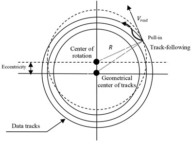
Servo control is essential in data storage systems to achieve high storage capacity and high data transfer rate. The main task of the tracking servo system is to position the optical head actuator following the spiral data track as accurately as possible during write/read operations in the presence of disk eccentricity and other unknown force disturbances caused by the mechanical vibrations in the drive. The major disturbance of tracking servo system is from run-out vibration caused by disk eccentricity. As shown in Fig. 1, the eccentricity is defined by the mismatch of a rotational center with respect to the geometrical center of the data tracks. The main sources of eccentricity are inaccurate formation of tracks on disc and inaccurate disc clamping. To follow a data track, the tracking servo system should be turned on at the moment a data track is crossed. The tracking controller should be able to suppress the radial velocity and stably pull in the beam spot onto the data track and sustain the track following operation. The radial velocity is proportional to the eccentricity, the rotational speed and the geometric position of the beam spot, and therefore is time-varying. In tracking servo system of an optical disk drive, the eccentricity of optical disk will cause periodic disturbance on TE (tracking errors) signal. The disturbance can be seen as a sinusoidal signal added to the output of the actuator system, whose frequency is proportional to the disk rotating speed [2].
Fig. 1Effect of eccentricity in the tracking servo control
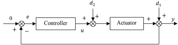
The other major disturbances in optical data storage systems are the vibration induced force disturbances caused by the misalignment of the motor spindle and the windage of the air currents arising from the pumping action of the rapidly rotating disks. These force disturbances have both deterministic and random properties and can be considered as input disturbance added to the actuator system. Therefore, the overall tracking servo system can be formulated as a regulation problem against the unknown exogenous disturbances located at the input and output sides of the plant, in which the deterministic components have relatively large magnitudes and are usually synchronized with the disk rotational frequency. The track servo control block diagram is shown in Fig. 2, where is the tracking error which is supposed to be zero, is the control input, is the run-out disturbance, and is the equivalent force disturbance which can be represented as , where denotes the deterministic component and denotes the random component. In next generation optical storage systems, due to the requirement of optics specification the tracking error should be less than 20 nanometers under various unknown circumstances. In order to suppress the disturbances effectively, in the following, an adaptive regulator design approach is proposed for the tracking servo system to deal with the unknown characteristic of disturbances.
Fig. 2Control block diagram of the tracking servo system
3. Design of the adaptive regulator
The control problem in Fig. 2 can be formulated as a disturbance regulation problem, where it is desired to construct an output feedback controller to regulate the performance variable against the unknown external disturbance signal and In the following, a Youla-Kucera parameterized adaptive regulation approach is proposed to attenuate the unknown disturbances.
The constructing of the proposed adaptive controller mainly consists of three steps. Firstly, a base controller is designed to increase the gain of the open loop system in the frequency range where the random disturbance locates, so that the random disturbance can be properly attenuated and the closed loop system is internal stable. Secondly, the base controller is augmented with parameter to form a Youla-Kucera () parameterized all stabilizing controllers, which satisfies the interpolation condition of Internal Model Principle (IMP) to perfectly reject the deterministic disturbance. Thirdly, if the property of the deterministic disturbance is assumed to be unknown and possibly time varying, then the adaptive algorithm is developed to online tune the parameter to the desired values so that the unknown deterministic disturbance can be perfectly rejected.
3.1. Youla-Kucera parameterization of stabilizing controllers
The Youla-Kucera parameterization of stabilizing controllers, also referred to in the literature as the parameterization, is a method that allows the construction of sets of stabilizing controllers for a given linear time-invariant system, where each controller is expressed as a function of a stable mapping, or parameter. The approach to the construction of such controller was first introduced by Youla [13] in a continuous time setting and later has been developed in a discrete time setting by Kucera [14]. In the following, a base controller is first designed to properly attenuate the random disturbance , then an adaptive regulator is further formulated with the parameter so that the deterministic disturbances and can be perfectly rejected. The main idea behind the adaptive algorithm developed in this paper is to search online for the desired parameter within the set of Youla-Kucera parameterized stabilizing controllers to achieve exact regulation against the exogenous inputs and .
In the optical data storage systems, the actuation to an objective lens for tracking is achieved by a voice-coil actuator, which can be modelled as a mass spring-damper system. The actuator transfer function from the control current to the displacement of the objective lens is normally considered as a two- or three-order linear system. Denote the discrete-time representation of as where and are polynomials in the complex variable . A stabilizing controller is designed as the base controller for the plant to make the closed loop system internal stable and the random disturbance be properly attenuated. Since in the optical data storage systems the random disturbance usually locates at the low frequency range, can be simply designed as a traditional lead-lag controller to raise the open loop system gain in the corresponding frequency range. The other optimal controller design approaches can be also used, i.e. the loop shaping approach or LQG approach [15]. Denote , and is a stable transfer function. Using the base stabilizing controller , the set of all stabilizing controllers can then be constructed based on the Youla-Kucera parameterization approach. In fact, for any , the controller given by:
is a stabilizing controller for the plant . Moreover, every rational stabilizing controller has the form for some . Let be the transfer matrix of the augmented plant with inputs and outputs , where is the disturbance vector, is the control input, is the performance variable to be regulated and is the measurement signal to be fed to the controller, then given a stabilizing controller as in Eq. (1), the regulation problem against the disturbance can be formulated with the and blocks as shown in Fig. 3. The block is given by:
Fig. 3Closed loop system with a Q-parameterized controller
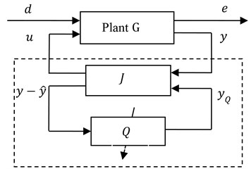
For the track servo system, we can define the measured track error signal which is supposed to be zero, then the augmented plant can be represented as , where and . The two blocks and can be combined into a single block given by where and . In this paper, a weighted Ritz-type parameter is considered as:
where is used to adjust the dynamic properties of and thereby optimally shape the sensitivity functions of the closed loop system. Normally is practically selected as a weight function with band pass or multiple narrow band pass features corresponding to the frequency range of the deterministic disturbances. Let and denote the transform of the performance variable and the disturbance input , respectively. The closed loop system performance variable is then given by:
Define the parameter vector for the weighted Ritz-type parameterization Eq. (2). Consider the deterministic disturbances and suppose the total number of the different poles in the expression for is . Then the interpolation condition for achieving regulation against the deterministic disturbance in the closed loop system can be written as [16, 17]:
where , and are the corresponding interpolation matrices. If we choose , then there exists a feasible solution of that can make the closed loop system achieve exact regulation against the deterministic disturbance and .
3.2. Adaptive algorithm
In the case where the disturbance input properties are unknown and possibly time varying, it is desired to introduce adaptation in the controller design process. The aim of the adaptation is to tune the parameter vector so that it converges to the desired parameter vector needed to achieve regulation. Let denote the time step delay operator, and , where . The performance variable is then given by:
where is one of the outputs of the block and thus can be obtained at each step . Let be a parameter vector satisfying the interpolation condition Eq. (4) and be the Youla parameter that results from using . The corresponding performance error resulting from can be then written as:
Define the signals and the error:
Define and the regression vector:
Define the estimated parameter vector and , then the error can be written as:
The corresponding posteriori error is:
The estimation of the unknown parameter vector can then be performed using different algorithms such as a gradient adaptation algorithm or recursive adaptive algorithms. For example, the recursive least squares algorithm with a time varying forgetting factor can be given as follows:
with , , and where is a time varying forgetting factor satisfying . Since is selected as a filter with band pass or multiple narrow band pass features w.r.t. the deterministic disturbances and the posteriori errors are used in the adaptation, the above algorithms maintain good performance when the adaptation input contains random disturbance. and are all stable transfer functions, then if the disturbance is bounded, based on Eq. (7) it is easy to obtain that the regressive vector is bounded. Thereby, based on Strict Positive Real (SPR) condition, if it is assumed that there exists a parameter vector satisfying the regulation condition Eq. (4) corresponding to the disturbance input properties and the random disturbances locate outside the band pass frequency range of , then the algorithm given by Eq. (10) yields and regulation against the disturbance and in the adaptive closed loop system can be achieved [12].
4. Experimental results
In this section, the proposed adaptive control approach is evaluated on a DVD optical storage servo control platform to verify the control ability of rejection of the periodic or time varying disturbance signals with unknown properties. Since the main disturbances in the tracking servo loop come from the disk eccentricity and other mechanical vibration, which are synchronized with the disk rotation, the standard control approach is to use a lead-lag controller which makes the resulting open loop gain satisfy the following equation [2, 3]:
where and is the crossover frequency of the open loop transfer function. The constant provides the crossover frequencies of the lead-lag network of the servo with the lead break frequency and the lag frequency . The constant is usually set around 3. Based on Eq. (13), it can be seen that selecting the higher crossover frequency can increase the open loop gain, and therefore improve the disturbance attenuation rate in the closed loop system. However the overly high open loop gain could decrease the robustness of the closed loop system and also make the tracking servo loop become too sensitive to the noise and other high frequency disturbance such as the disk scratch. For the adaptive regulator proposed in this paper, the lead-lag controller designed from Eq. (13) is adopted as the base controller to attenuate the low frequency disturbance, e.g. the random force disturbance, however, the perfect rejection of the deterministic disturbance with the relatively large magnitude is achieved using the augmented adaptive parameter. For this case, the disturbance attenuation performance can be improved without the necessity of overly boosting the open loop gain in the whole frequency range and consequently the robustness of the closed loop system is increased.
The experimental setup for the evaluation of the proposed adaptive control approach is shown in Fig. 4. The optical pick-up head SF-HD850 from Sanyo Corporation is used as the actuator to move the objective lens. The control chipset AM5668 is used to amplify the control signal to actuate the optical pick-up head SF-HD850 with an amplification gain 23.5 dB. The adaptive control algorithm is implemented in Matlab with the Real-time Windows Target on a Microsoft Windows PC at a sampling rate 4 KHz. The Polytec OFV552/5000 is used to measure the displacement of the optical lens. The analogue input/output card NI PCI6221 is installed in the PC as the input interface connected to the displacement measurement of the optical lens from Polytec OFV552/5000 and the output interface connected to the VTRACK pin of AM5668, respectively. During the experimental testing, the voice coil actuator was flying on the rotating disk of a dismounted hard disk drive at a fixed rotation speed 4800 rpm. The additional disk eccentricity signal with the frequency of 80 Hz is produced by a signal generator Agilent 33522A and is added to the measurement signal of the lens displacement. An equivalent force disturbance signal with both deterministic and random properties is added into the VTRACK signal. The eccentricity is assumed to be 10 um and the force disturbance is considered as the random signal located within the frequency range 0-20 Hz along with a sinusoidal signal at 80 Hz.
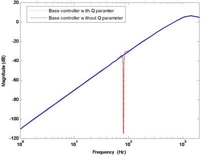
The plant model of pick-up head SF-HD850 in the tracking servo loop is obtained using system identification method as First, the base controller is designed as a lead-lag controller based on Eq. (13) with the open loop crossover frequency set as 1 KHz. The parameter is selected to be of the form , where is a band pass Butterworth filter with the roll off frequencies around 70 Hz and 100 Hz, respectively. When the disturbance frequency is assumed to be known at 80 Hz, then the parameter which can achieve the regulation can be obtained based on the interpolation condition Eq. (4). Fig. 5 shows the modulus of the output sensitivity function of the resulting closed loop systems, where the solid line is for the case of the base lead-lag controller without the parameter and the dashed line is for the case of considering the parameter. It can be seen that the random disturbance within 0-20 Hz can be effectively attenuated with the base lead-lag controller, however, the deterministic disturbance at 80 Hz should be rejected with the augmented parameter. By properly choosing the weight function the baseline loop shape is not amplified in the whole frequency range. When the disturbance is unknown, the proposed adaptive algorithm is used to tune in the parameter online to achieve regulation. The forgetting factor in the adaptation algorithm is set as a constant . The initial conditions for the adaptation algorithm are and where is 4×4 identity matrix. In the adaptation algorithm, the UD factorization algorithm is used in order to improve the numerical properties of the algorithm.
Fig. 4The photo of the experimental setup system
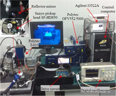
Fig. 5Modulus of the output sensitivity function for the case of disturbance frequency at 80 Hz
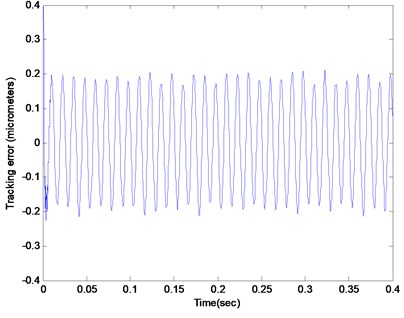
The experimental results are shown in Figs. 6-11. Fig. 6 shows the result of the tracking error of the actuator system subjected to the random force disturbance within the frequency range 0-20 Hz. During the time from 0 to 0.2 second, the actuator system operated in open loop, and it can be seen that the lens vibrated under the random force disturbance with a tracking error up to 4 micrometers. When the base lead-lag controller was applied at 0.2 second, the tracking error immediately dropped down to 10 nanometers, which implies that the lead-lag controller designed based on Eq. (13) can effectively attenuate disturbance in the low frequency range. However, when the system was subjected to the random force disturbance and the deterministic eccentricity disturbance with frequency at 80 Hz simultaneously, the magnitude of the tracking error increased and reached more than 150 nanometers as shown in Fig. 7. This result implies that the lead-lag controller cannot properly attenuate the deterministic disturbance with a relatively high frequency.
Fig. 6The tracking error of the system subjected to the random force disturbance. (The open loop system from 0 to 0.2 second vs. the closed loop system with the base lead-lag controller from 0.2 to 0.4 second)
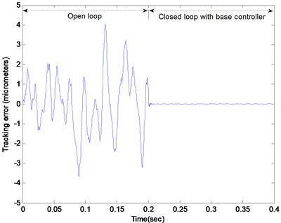
Fig. 7The tracking error of the closed loop system with the base lead-lag controller subjected to the random force disturbance and the eccentricity disturbance with frequency at 80 Hz
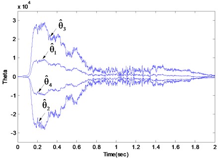
The corresponding experimental result with the adaptive parameterized controller is presented in Figs. 8 and 9, which shows that the tracking error had dropped down to blow 15 nanometers and the estimated parameter converged to the desired values accordingly. Figs. 10 and 11 shows the result for the adaptive parameterized closed loop system when a chirp type force disturbance sweeping from 70 Hz to 90 Hz with a chirp rate at 10 Hz/s was added along with the random force disturbance and the deterministic eccentricity disturbance. It can be seen that the parameter could adjust online w.r.t the time-varying property of the deterministic disturbances and consequently the tracking error still could be kept blow a desired value.
The experimental results demonstrate that the proposed parameterized adaptive controller can attenuate the random and the periodic or time varying deterministic disturbances effectively in the tracking servo control loop. Therefore, for the next generation data storage system in which the even tighter tacking error tolerance and the higher disk rotating speed are demanded, the parameterized adaptive control approach can be adopted to avoid overly boosting the open loop gain with the traditional lead-lag controllers and thereby the overall control performance and the robustness in the tracking servo loop are enhanced.
Fig. 8The tracking error of the Q parameterized adaptive closed loop system subjected to the random force disturbance and the eccentricity disturbance with frequency at 80 Hz
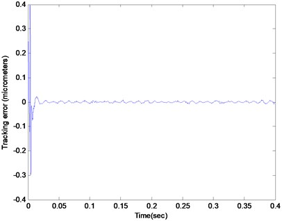
Fig. 9The estimated parameter θ^ of the Q parameterized adaptive closed loop system subjected to the random force disturbance and the eccentricity disturbance with frequency at 80 Hz
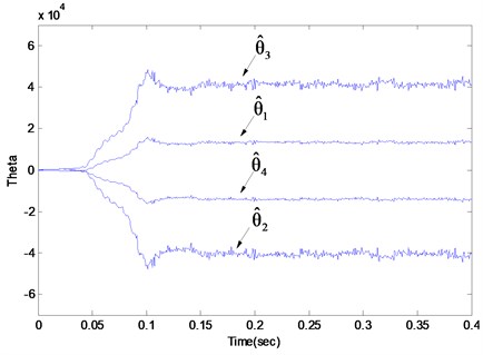
Fig. 10The tracking error of the Q parameterized adaptive closed loop system subjected to the random force disturbance and the eccentricity disturbance at 80 Hz along with a chirp type force disturbance with frequency from 70-90 Hz
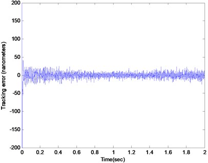
Fig. 11The estimated parameter θ^ of the Q parameterized adaptive closed loop system subjected to the random force disturbance and the eccentricity disturbance at 80 Hz along with a chirp type force disturbance with frequency from 70-90 Hz
5. Conclusion
The reduction of tracking error is critical to increase the data storage density in next generation optical data storage systems. In this paper, an adaptive regulation approach is proposed to maintain the tracking error at a desired value despite the unknown vibration induced disturbances. The regulator design approach based on the Youla-Kucera () parameterization of stabilizing controllers is first presented, where the deterministic and the random disturbances are considered separately. Then an adaptive approach is proposed to tune the parameter online in the expression of stabilizing controllers in order to yield regulation against the unknown deterministic disturbances. The performance of the proposed control approach is evaluated with experimental results showing that the tracking error can be effectively maintained at the desired value despite the unknown and time varying disturbances. These results also demonstrate the potential of the proposed adaptive regulation approach in the wide range of applications such as in active vibration and noise control field.
References
-
Park K., Park Y., Park N. Prospect of recording technologies for higher storage performance. IEEE Transactions on Magnetics, Vol. 47, Issue 3, 2011, p. 539-545.
-
Cherubini G., Chung C. C., Messner W. C. Control methods in data-storage systems. IEEE Transactions on Control Systems Technology, Vol. 20, Issue 2, 2012, p. 296-322.
-
Lim J. S., Ryoo J. R., Lee Y. I., Son S. Y. Design of a fixed-order controller for the track-following control of optical disc drives. IEEE Transaction on Control System Technology, Vol. 20, Issue 1, 2012, p. 205-213.
-
Ryoo J. R., Jin K., Moon J. H., Chung M. J. Robust disturbance observer for the track-following control system of an optical disk drive. Control Engineering Practice, Vol. 12, 2004, p. 577-585.
-
Lee J. I., Chung C. C. Design of a new multi-loop disturbance observer for optical disk drive systems. IEEE Transactions on Magnetics, Vol. 45, Issue 5, 2009, p. 2224-2227.
-
Kim K. S., Rew K. H. Reduced order disturbance observer for discrete-time linear systems. Automatica, Vol. 49, Issue 4, 2013, p. 968-975.
-
Leyva-Ramos J., Ortiz-Lopez M. G., Diaz-Saldierna L. H. Disturbance rejection control scheme for optical disk drive systems. IEEE Transactions on Magnetics, Vol. 46, Issue 10, 2010, p. 3772-3777.
-
Chen X., Tomizuka M. New repetitive control with improved steady-state performance and accelerated transient. IEEE Transaction on Control System Technology, Vol. 22, Issue 2, 2014, p. 664-675.
-
Herrmann G., Hredzak B., Turner M., Postlethwaite I., Guo G. Discrete robust anti-windup to improve a novel dual-stage large-span track seek/following method. IEEE Transactions on Control System Technology, Vol. 16, Issue 6, 2008, p. 1342-1351.
-
Conway R., Choi J., Nagamune R., Horowitz R. Robust track-following controller design in hard disk drives based on parameter dependent Lyapunov functions. IEEE Transactions on Magnetics, Vol. 46, Issue 4, 2010, p. 1060-1068.
-
Shahsavari B., Conway R., Keikha E., Zhang F. Horowitz R. Robust track-following controller design for hard disk drives with irregular sampling. IEEE Transactions on Magnetics, Vol. 49, Issue 6, 2013, p. 2798-2804.
-
Landau I. D., Lozano R., M’Saad M., Karimi A. Adaptive Control: Algorithm, Analysis and Applications. Springer-Verlag, London, 2011.
-
Youla D. C., Jabr H. A., Bongiorno J. J. Modern Wiener-Hopf design of optimal controllers: Part I. IEEE Transactions on Automatic Control, Vol. 21, Issue 1, 1976, p. 3-13.
-
Kucera V. Discrete Linear Control: The Polynominal Equation Approach. John Wiley and Sons, New York, London, Sydney, 1979.
-
Zhou K., Doyle J., Glover K. Robust and Optimal Control. Prentice Hall, New Jersey, NJ, USA, 1995.
-
Wu Z., Ben Amara F. Regulator synthesis for bimodal linear systems. IEEE Transactions on Automatic Control, Vol. 56, Issue 2, 2011, p. 390-394.
-
Wu Z., Ben Amara F. Youla parameterized adaptive regulation against sinusoidal exogenous inputs applied to a benchmark problem. European Journal of Control, Vol. 19, Issue 4, 2013, p. 289-299.
About this article

This work was supported by the National Natural Science Foundation of China (51075254), Shanghai Municipal Natural Science Foundation (15ZR1415800), the Innovation Program of Shanghai Municipal Education Commission (14ZZ092) and the Scientific Research Foundation for the Returned Overseas Chinese Scholars.
